Note: Descriptions are shown in the official language in which they were submitted.
CA 02458033 2004-02-19
WO 03/022480 PCT/US02/28662
CRIMPING ASSEMBLY
CROSS-REFERENCE TO RELATED APPLICATIONS
This application claims the benefit of the U.S. Provisional Application Serial
No. 60/318,804, filed September 11, 2001.
s FIELD OF THE INVENTION
The present invention relates generally to a crimping assembly for crimping a
fitting to connect sections of pipe and, more particularly to a crimping
assembly
including an actuator assembly and a crimp ring.
BACKGROUND OF THE INVENTION
io A crimp or press-style fitting is typically a tubular sleeve containing
seals.
The fitting is compressed in radial directions to engage the ends of pipes.
The fitting
forms a leak resistant joint between the pipe ends. The joint has considerable
mechanical strength and is self supporting. A crimping tool and crimping
assembly
are used to crimp the fitting. The crimping assembly can include jaws
activated by
is the crimping tool for directly crimping the fitting. Alternatively, for
larger fittings,
the crimping assembly can be an actuator assembly having arms that actuate a
crimp
ring to crimp the fitting.
Referring to Figure 1, components of a typical crimping tool 10, actuator
assembly 18, and crimp ring 50 in accordance with the prior art are
illustrated. The
ao crimping tool 10 and actuator assembly 18 are shown partially unassembled
to reveal
relevant details. The crimping tool 10 includes a cylinder 12, a hydraulic
piston 14,
and an engagement member 16, such as a carriage having rollers 17. The
actuator
assembly 18 couples to the crimp tool 10 by methods known in the art. The
actuator
assembly 18 includes first and second actuator arms 20a and 20b, first and
second
zs side plates 40 and one not shown, and pivot pins 44.
Each actuator arm 20a and 20b includes a cam end 22 and a crimp end 24.
The cam end 22 includes a surface 23 for contacting one of the rollers 17 of
the
engagement member 16 attached to the end of the hydraulic piston 14. The
surfaces
23 of the prior art do not control the input force applied thereon by the
rollers 17
CA 02458033 2004-02-19
WO 03/022480 PCT/US02/28662
_2_
versus displacement of the piston 14 when used with various fittings.
Typically, the
surfaces 23 of the prior art include a portion defined by a radius and include
a portion
defined by a line. In the present example, the crimp ends 24 of the arms 20a
and 20b
couple to the crimp ring 50 to crimp larger fittings.
s The crimp ring 50 has a plurality of ring portions. In the present example,
the
crimp ring 50 has two portions 52a and 52b with each having an indentation 54
for
receiving a crimp end 24 of the arms 20a and 20b. The portions 52a and 52b are
pivotably connected together by a pin 56. The crimp ends 24 of the arms 20a
and 20b
couple respectively to the portions 52a and 52b.
io In the prior art, the actuator arms 20a and 20b each define pockets 34, as
best
shown by the cross-section of arm 20b. The pocket 34 has two sidewalk 36 with
one
not shown in the cross-section of arm 20b. The two sidewalk 36 each define an
indentation 36. The actuator assembly 18 includes a torsion spring 30 and a
pin 32.
The pin 32 disposes in the torsion spring 30. The spring 30 and pin 32 are
positioned
is in the pockets 34 between the arms 20a and 20b. The pin 32 fits into the
indentations
38 in the sidewalk 36 to hold and stabilize the spring 30. The spring 30
biases the
crimp ends 24 together, which facilitates handling of the assembly 18 and
crimp ring
50 when positioning on a fitting.
In operation, a hydraulic pump (not shown) builds up hydraulic pressure in the
ao cylinder 12 to move the piston 14 and press the rollers 17 of the
engagement member
16 against the arms 20a and 20b. The rollers 17 engage the surfaces 23 of the
arms
20a and 20b, causing the arms 20a and 20b to rotate. Depending on the intake
angle
of the rollers 17 on the surfaces 23, a crimping force up to about 100 kN may
be
produced when measured at the crimp coupling centerline. Typically, the
crimping
zs time may be about 4 seconds, and the hydraulic output may be about 32 kN
from the
piston 14 of the crimping tool 10 to produce the input force to the crimping
assembly
18.
When the arms 20a and 20b are actuated by displacement of the engagement
member 16 associated with the hydraulic piston 14, the crimp ends 24 move
together
so to actuate the crimp ring 50. The developed crimping force closes the
portions 52a
CA 02458033 2004-02-19
WO 03/022480 PCT/US02/28662
_3_
and 52b about the fitting. In some embodiments, the crimp ring 50 may pivot on
the
crimp ends 24 to enable an operator to crimp the fitting in locations of
obstructed or
limited accessibility.
The life and failure mode of crimping assemblies of the prior art, such as
s discussed above, may be unacceptable. The actuator arms undergo intense
forces
when crimping and can fail, which is undesirable. In the prior art, crimping
assemblies have included straps attached to the arms to retain them on the
assembly if
they do fail.
In addition, crimping assemblies of the prior art may not always give an ideal
io or near ideal crimp on the fitting. In other words, the prior art crimping
assemblies
may not uniformly apply a crimping force to the fitting over the displacement
of the
1
piston. Furthermore, the force versus displacement profiles of the prior art
crimping
assemblies may not be consistent when used with fittings of various sizes,
materials,
or tolerances and especially when used with fittings having larger diameters
up to 4-
is in.
Referring to Figures 2A-F, graphs of force profiles 60a-f are provided from
test results using a prior art actuator assembly to actuate typical crimp
rings to crimp
fittings of various sizes. In Figures 2A-F, the input force (kN) as applied to
the piston
(14) is plotted against the piston displacement (in.) of the hydraulic piston
engaging
ao the actuator assembly. Each force profile 60a-f includes plots of three
crimp
operations.
Force profiles 60a-f illustrate test results using the prior art actuator
assembly
actuating typical, prior art crimp rings to crimp a 2.5-in. fitting on type K
copper
tubing, a 2.5-in. fitting on type M copper tubing, a 3-in. fitting on type K
copper
is tubing, a 3-in. fitting on type M copper tubing, a 4-in. fitting on type K
copper tubing,
and a 4-in. fitting on type M copper tubing, respectively. In all cases, the
material and
geometry of the copper tubing are governed by the standard specification, ASTM
B~~, for seamless copper water tubing. For the force profiles 60a-f, the
piston
displacement of 0-inch corresponds to the point where the rollers 16 just make
contact
3o with the surfaces 23 of the arms 20a and 20b while the crimp ring 50
contacts an
CA 02458033 2004-02-19
WO 03/022480 PCT/US02/28662
-4-
undeformed fitting. For clearance and for opening the actuator, it is
understood that
additional displacement of the piston of 2 to 3-mm typically exists before the
rollers
16 make contact with the surfaces 23.
Each of the force profiles 60a-f includes an initial portion 62, a sustained
s portion 64, and a ramp portion 66. Some of the force profiles 60a-f require
a
significant amount of stroke to reach the sustained portion 64. For example,
the force
profile 60a in Figure 2A requires roughly 0.6-in. of displacement before
reaching 20
kN. The force profile 60b in Figure 2B requires roughly 0.7-in. of
displacement
before reaching 20 kN. Some of the force profiles 60a-f have peaks where the
force
io spikes generally higher than is ideally desirable when crimping fittings of
various
diameters. For example, the force profile 60d in Figure 2D includes a peak 65
approaching nearly 30 kN at the displacement of approximately 0.9-in. Some of
the
force profiles 60a-f have sustained portions 64 with a higher force in general
than is
ideally desirable when crimping fittings of various diameters. For example, in
the
is force profile 60c in Figure 2C, the sustained portion 64 attains a level
between 26 and
28 kN.
In the force profiles 60a-f, the total stroke (i.e., displacement of the
hydraulic
piston) extends for a longer displacement than is ideally desirable when
crimping
fittings of various diameters. The prior art actuator assembly and crimp rings
require
ao an excessive amount of stroke on the order of over 1.4-in. to crimp the
larger fittings
of 2.5, 3, and 4-in. The stroke length of over 1.4-in. is excessive when
compared to
the amount of stroke used by smaller sized assemblies, such as a 0.5-in.
stroke for a
1/2-in. jaw assembly and a 1.2-in. stroke for a 2-in. jaw assembly.
The stroke length of over 1.4-in. is also excessive when compared to the
is amount of stroke available in a typical crimping tool. For example, the
total available
stroke of the typical crimping tool is approximately 40-mm or 1.57-in. with
approximately 36-mm or 1.42-in. of that stroke being desirable for use in
normal
designs to accommodate manufacturing tolerances and to allow for clearance
between
the rollers and the actuator arms. Requiring over 1.4-in. of stroke length,
the prior art
3o crimping assembly lies close to the usable stroke limit.
CA 02458033 2004-02-19
WO 03/022480 PCT/US02/28662
-5-
Additionally, the prior art actuator assembly and crimp ring used to crimp the
3-in. fitting exhibited a tendency towards an excessively high peak 65 before
reaching
the final force of 32 kN. As shown in Figure 2D, the peak is nearly 30 kN. If
the
premature peak triggers the pressure relief setting of 32 kN, this premature
peaking
s could potentially cause the crimping tool to shut down before a completed
crimp is
formed with the actuator assembly and crimp ring. It is understood that the
pressure
relief setting of 32 kN can vary within a range, depending on the specific
tool or type
of tool being used and depending on a number of variables, such as voltage
levels,
tolerances, and temperature effects, among other variables.
io The present invention is directed to overcoming or at least reducing one or
more of the problems set forth above.
SUMMARY OF THE INVENTION
One aspect of the present invention discloses an improved assembly used with
a displaceable member for actuating the assembly. The assembly includes an arm
is pivotably disposed in the assembly and having an edge. A profile is defined
on the
edge and is capable of being engaged by the displaceable member. The profile
includes a first portion defining a radial contour of the edge, a second
portion adjacent
the first portion and defining a curved contour of the edge, and a third
portion
adjacent the second portion and defining a straight contour of the edge.
zo Another aspect of the present invention discloses an arm used with a
displaceable member for actuating the arnl. The arm includes a first end and
an edge
adjacent the first end. A profile is defined on the edge and is capable of
being
engaged by the displaceable member. At least a portion of the profile is
defined by a
non-linear, non-radial contour of the edge. In a further aspect, the profile
may include
zs a first portion being immediately adjacent the first end and defined by a
radius, a
second portion being adjacent the first portion and defined by the non-linear,
non-
radial contour, and a third portion~being adjacent the second portion and
defined by a
linear function.
Another aspect of the present invention discloses an assembly used with a
3o displaceable member for actuating the assembly. The assembly includes a
plate, a
CA 02458033 2004-02-19
WO 03/022480 PCT/US02/28662
-6-
- pin, and an arm. The plate defines a first aperture and has a first
hardness. The pin is
disposed in the first aperture and has a second hardness. The second hardness
is equal
to or greater than the first hardness of the plate. The arm is positioned
adjacent the
plate and defines a first pivot aperture for the pin. The arm is rotatably
disposed on
s the pin and is capable of being rotated by engagement with the displaceable
member.
The arm has a third hardness. The third hardness is greater than the first
hardness.
The arm can include a maximum section height at the first pivot aperture. The
plate
can have an edge defining a stress concentrator adjacent the first aperture.
The first
hardness can be approximately 30 to 35 Rc, and the third hardness can be
io approximately 56 to 59 Rc.
Yet another aspect of the present invention discloses an assembly used with a
displaceable member for actuating the assembly. The assembly includes a first
arm
disposed in the assembly, a second arm disposed in the assembly, and a biasing
member disposed in the assembly. The first ann has a first end and a first
side
is adjacent the first end. The second arm has a second end and a second side
adjacent
the second end. The biasing member is disposed between the arms. The biasing
member has a first portion adjacent the first side and has a second portion
adjacent the
second side. A first pin is disposed in a first hole defined in the first
side. The first
pin engages the first portion to hold the biasing member between the arms. A
second
ao pin on the second side can also be disposed in a second hole defined in the
second
side and can engage the second portion to hold the biasing member between the
arms.
The biasing member can be a leaf spring.
The foregoing summary is not intended to summarize each potential
embodiment or every aspect of the invention disclosed herein.
as BRIEF DESCRIPTION OF THE DRAWINGS
The foregoing summary, a preferred embodiment, and other aspects of the
present invention will be best understood with reference to a detailed
description of
specific embodiments of the invention, which follows, when read in conjunction
with
the accompanying drawings, in which:
CA 02458033 2004-02-19
WO 03/022480 PCT/US02/28662
_7_
Figure 1 illustrates components of a crimping tool, actuator assembly, and
crimp ring according to the prior art.
Figures 2A-F illustrate test results graphing force versus displacement for an
actuator assembly and crimp rings according to the prior art.
s Figure 3 illustrates a graph of an "ideal" force profile in conjunction with
a
near ideal force profile according to the present invention.
Figure 4 illustrates an exploded view of an embodiment of an actuator
assembly according to the present invention.
Figures SA-B illustrate various view of an arm of the actuator assembly of
io Figure 4.
Figures 6A-C illustrate test results graphing force versus displacement for an
actuator assembly according to the present invention.
Figure 7 illustrates an exploded view of an embodiment of a crimp ring
according to the present invention.
is Figure 8 illustrates details of an actuator arm in accordance with the
present
invention as compared to a prior art actuator arm.
Figure 9A-B illustrate various views of a side plate of the actuator assembly
of
Figure 4.
While the invention is susceptible to various modifications and alternative
zo forms, specific embodiments have been shown by way of example in the
drawings
and will be described in detail herein. However, it should be understood that
the
invention is not intended to be limited to the particular forms disclosed.
Rather, the
invention is to cover all modifications, equivalents, and alternatives falling
within the
scope of the invention as defined by the appended claims.
zs DETAILED DESCRIPTION OF THE INVENTION
Referring to Figure 3, a graph illustrates an "ideal" force profile in
conjunction
with a near ideal force profile in accordance with the present invention. The
"ideal"
force profile 70 includes a first step 72, a sustained portion 74, and an end
step 76.
The first step 72 reaches a crimping force with minimal displacement of the
tool. The
CA 02458033 2004-02-19
WO 03/022480 PCT/US02/28662
_g_
sustained portion 74 is about 75% of a shutoff force and occurs consistently
over the
displacement of the tool. The end step 76 rapidly reaches the shut off force
of the
crimping tool, typically 32 lcN. In general, the "ideal" force profile 70
requires a
small stroke or displacement to accomplish the crimping.
s A near ideal force profile 80 of the present invention attempts to meet the
"ideal" force profile 70. The near ideal force profile 80 has a longer stroke
than the
"ideal" force profile 80, because the near ideal force profile 80 requires
more
displacement to complete the same amount of work to crimp the fitting. It is
understood, however, that differences between the "ideal" force profile 70 and
the
io near ideal force profile 80 of the present invention exist due to a number
of variables:
including deflections of components; differences in tolerances; temperature
effects;
materials of the fittings, the actuator anus, and the crimp rings; and aspects
determined by the plastic deformation of metals.
The near ideal force profile 80 in accordance with the present invention
is includes a first initial portion 82, a second sustained portion 84, and a
third ramp
portion 86. The initial portion 82 is governed by immediate changes in the
deformation of the fitting and deflection of the tool. The initial portion 82
preferably
requires little stroke length before reaching a substantially consistent force
of the
sustained portion 84. The ramp portion 86 preferably rapidly reaches the shut
off
ao force.
To accomplish a force profile similar to the near ideal force profile 80 in
Figure 3 and to improve the life of a crimping assembly, the present invention
includes a number of improvements over the prior art. Referring to Figure 4,
an
embodiment of an actuator assembly 100 according to the present invention is
as illustrated in an exploded view. In the present embodiment, the actuator
assembly
100 actuates a crimp ring (not shown), such as discussed below with reference
to
Figure 7. Although the present embodiment of the actuator assembly 100 is
directed
to actuating crimp rings, one of ordinary skill in the art will appreciate
that the
teachings of the present invention are applicable to other crimping
assemblies, for
so example, assemblies including jaws for directly crimping fittings.
CA 02458033 2004-02-19
WO 03/022480 PCT/US02/28662
-9-
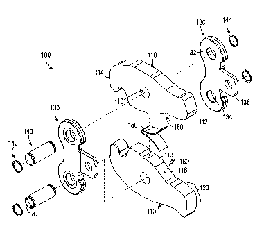
The actuator assembly 100 includes actuator arms 110, side plates 130, pivot
pins 140, and a biasing member 150. The actuator arms 110 are substantially
identical. Each of the arms 110 includes a first or cam end 112, a second or
crimp end
114, and a side portion 119. Each arm 110 also defines a pivot bore 116
therethrough
s that is substantially perpendicular to the longitudinal dimension of the arm
100. The
actuator arms 110 are disposed in the actuator assembly 100 with the side
portions
119 adjacent one another. The biasing member or leaf spring 150 is disposed
between
the actuator arms 110 and adjacent the side portions 119.
In conjunction with the spring 150, the actuator arms 110 of the present
io invention define holes 118 in the side portions 119. Holding pins 160 are
disposed in
the holes 118 to retain the spring 150 between the arms 110. Retaining the
spring 150
with a step, shoulder, or pocket formed into the side portions 119 is
undesirable. A
step, shoulder, or pocket in the arm 110, as done in the prior art, creates a
large stress
riser in the arm 110, causing early breakage.
is The side plates 130 are substantially identical and are disposed parallel
to one
another on either side of the arms 110. Each of the side plates 130 defines
pivot
apertures 132 and 134 and includes a portion 136 for connecting the assembly
100 to
a crimp tool (not shown). Relevant details of the side plate 130 are discussed
below
with reference to Figure 9A-B. The pivot pins 140 are positioned through the
~o apertures 132 and 134 in the side plates 130 and through the bores 116 in
the arms
110. Retaining rings 142 and 144 are disposed on the ends of the pivot pins
140 to
hold the assembly 100 together.
As best described above, rollers of a displaceable engagement member (not
shown) within the crimp tool contacts the cam ends 112 of the actuator arms
110,
as causing the actuator arms 110 to pivot respectively about the pivot pins
140 disposed
in their pivot bores 116. A crimping force is developed and applied to a crimp
ring
(not shown) coupled to the crimp ends 114. In contrast to the actuator
assemblies of
the prior art discussed above, the actuator arms 110 of the present invention
include
cam profiles 120, which control the application of the input force applied by
the
3o crimping tool on the arm 110 in relation to the displacement of the
engagement
CA 02458033 2004-02-19
WO 03/022480 PCT/US02/28662
-10-
member within the crimp tool. The cam profiles 120 produce a substantially
more
uniform or stable force profile on a number of different sized fittings and
crimp rings
than evidenced in the prior art. Therefore, the cam profiles 120 of the
present
invention are capable of substantially and uniformly applying the output force
over
s the displacement of the displaceable engagement member.
The cam profiles 120 of the actuator arms 110 determine the input force on the
arms 110 substantially required at a given displacement of the piston. In
turn, the cam
profiles 120 determine the resulting output force produced with the crimp
ring. To
accomplish a force profile similar to the "ideal" and near ideal force
profiles 70 and
io 80 in Figure 3, the cam profiles 120 of the actuator assembly 100 are
designed to
provide a very specific input force versus displacement curve. The desired
constraints
on the application of the input force by the cam profiles 120 are as follows.
First, the cam profiles 120 preferably minimize the displacement or stroke
required to crimp various sized fittings, for example 2.5, 3, and 4-in.
fittings. Second,
is the cam profiles 120 preferably remove or limit any peaks in the force
profile from
occurring before attaining the tool shut off force, for example 32-kN. Third,
the cam
profiles 120 preferably lower the required or sustained input force from the
start of
crimping until the very end of the stroke as much as possible. For example,
the cam
profiles 120 of the present invention attempt to lower the required force from
the start
ao of crimping until the very end of the stroke as much as possible. The
sustained force
preferably occurs for approximately 80% of the stroke, and the force
preferably ramps
rapidly to the shut off force for the remaining 20% of the stroke. Fourth, the
cam
profiles 120 preferably complete the above three constraints for all three
sizes of
fitting without adversely affecting any one size. Lastly, the cam profiles 120
is preferably meet the dimensional constraints of the crimping tool, such as
the diameter
of the rollers, stroke of the piston, and position of the pivot pins.
To develop a model of a cam profile to meet these constraints, testing was
performed using an existing actuator assembly to understand the crimp force
required
at the crimp ring. An algorithm for the cam profile model was developed to
perform
3o calculations. The algorithm accounted for system deflections, such as
deflections of
CA 02458033 2004-02-19
WO 03/022480 PCT/US02/28662
-11-
the side plates and arms of the existing assembly, in relation to the
positioning of the
crimp ends and the changing of the angles on the cam ends of the arms. A
spreadsheet was used for the calculations.
First, a generalized crimp ring force profile was analyzed with respect to the
s existing actuator assembly, such as described above with reference to
Figures 1 and 2.
To test the algoritlnn, dimensional information from the existing actuator of
the prior
art was input into the algorithm, along with the crimp ring force data. An
actuator
input force verses displacement curve was generated, which was compared to
actual,
recorded test data using the existing actuator assembly. From the comparison,
it was
io determined that there was a difference due to friction and a slight
difference in the
model, among other differences. The cam profile model was then slightly
modified
using experimentally derived correction factors to obtain agreement with the
actual
data.
Then, this cam profile model and data were used to design a cam profile for
is actuator arms of an actuator assembly capable of controlling the input
force versus
displacement of the engagement member. An iterative process was performed to
generate points every 0.040" for the cam profile on the cam end of the arms;
however,
the points could have been generated at any small increment. The points were
based
on a desired tool input force and other inputs from the model. From this data,
the
ao information was translated into a cam profile 120 of the present invention
as
described below with reference to Figures SA-B.
Referring to Figures SA-B, an embodiment of an actuator arm 110 in
accordance with the present invention is illustrated in a side view and an
enlarged,
detailed view, respectively. A reference coordinate system (X, Y) is provided
in
as Figures SA-B. The coordinate system includes orthogonal axes X and Y for
describing the exemplary dimensions of the present embodiment of the actuator
arm
110 and cam profile 120. The axes X and Y have an origin O at the center of
the
pivot bore 116 about which the arm 110 rotates.
In general, the actuator arm 110 of the present embodiment has a length of
3o approximately 166.76-mm (6.565-in.) along the longitudinal axis X, a height
of
CA 02458033 2004-02-19
WO 03/022480 PCT/US02/28662
-12-
approximately 75.95-mm (2.990-in.) along the lateral axis Y, and a thickness
of
approximately 20-mm (0.787-in.) along a mutually orthogonal axis. The crimp
end
114 includes a tip having a radius of approximately 10-mm situated at a
reference
point 115 of approximately (-65, 21)-mm.
s As best illustrated in the detailed view of Figure SB, the cam profile 120
includes a first, radial portion 122; a second, curved portion 124; and a
third, ramped
portion 126. For illustrative purposes, geometric points A, B, C, and D are
provided
in Figures SB to show separation points between the first, second, and third
portions
122, 124 and 126.
io The first, radial portion 122 is defined by a radius R of approximately 15-
mm
(0.591-in.) at a point 123 having the coordinate (76.79, -4.02)-mm or (3.023, -
0.158)-
in. The first, radial portion 122 is immediately adjacent the cam end 112,
starting at a
point A on the cam end 112 and ending at point B of approximately (7.8, 86.03)-
mm
or (0.307, 3.387)-in. The first portion 122 is the portion of the cam profile
120 first
is contacting the rollers on the engagement member, as discussed above. In
terms of
controlling the input force versus displacement of the crimping tool, the
first portion
122 corresponds roughly to the initial portion of the input force versus
displacement
profile, such as the initial portion 82 discussed above in Figure 3. It is to
be
understood, however, that some overlap can exist between the portions of the
cam
ao profile 120 corresponding roughly to portions of the force profile produced
with the
cam profile 120.
The second, curved portion 124 of the cam profile 120 is substantially
contiguous with the first portion 122 and lies between the geometric points B
and C.
The point C is situated at the reference coordinate of approximately (14.42,
62.68)-
zs mm or (2.468,0.568)-in. The second, curved portion 124 of the cam profile
120 is
defined by a curved contour. Preferably, for the present embodiment, the
second
portion 124 is defined by a 10th order polynomial equation, as described
below. In
terms of controlling the input force of the crimping tool, the second portion
124
corresponds roughly to the sustained portion of the input force versus
displacement
3o profile, such as the sustained portion 84 discussed above in Figure 3.
CA 02458033 2004-02-19
WO 03/022480 PCT/US02/28662
-13-
The third, ramp portion 126 is substantially contiguous with the second
portion and lies between points C and D on the cam profile 120. The point D is
situated at the reference coordinate of approximately (53.55, 15.96)-rmn or
(2.108,
0.629)-in. The third, ramp portion 126 is defined by a linear equation having
a
s particular slope and location with respect to the center of rotation O. In
terms of
controlling the input force of the crimping tool, the third portion 126
corresponds
roughly to the ramp portion of the input force versus displacement profile,
such as the
ramp portion 86 discussed above in Figure 3.
The exemplary dimensions and values disclosed herein apply to the present
io embodiment of the actuator arm 100. It is understood that the magnitude of
these
values may differ for an arm having an overall smaller or larger dimension.
The
magnitude of these values may also differ for arms used on different fittings
or used
with different forces. Depending on such differences, one of ordinary skill in
the art
will appreciate that the relationship of the values may change or may remain
is substantially the same.
The second, curved portion 124 of the cam profile 120 is preferably defined by
a 10th order polynomial, as follows:
y=Ax'°+Bx9+Cx8+Dx'+Ex6+Fx5+Gx4+Hx3+Ixz+Jx'+K
where, the values of the constants A-K when the X-coordinate is given in terms
of
ao inches are as follows:
Tahla~ Vai"P~ of ~nnctant~ fir 1 Oth Order P~lvnomial
Variable Value
A -48.9913974944589
B 1463.61453291994
C -19630.1624858022
D 155664.66890622
E -808294.682548789
F 2871872.99972913
G -7071260.01718111
H 11914996.6049983
I -13149361.9925974
J 8582947.63458813
K -2516314.38595924
CA 02458033 2004-02-19
WO 03/022480 PCT/US02/28662
-14-
Using the 10th order polynomial equation with these constants, the points for
the second, curved portion 124 of the cam profile 120 can be obtained. For
example,
a point having a distance X = 2.7349-in. from the origin O at the pivot point
yields a
point of Y = -0.5238-in., which lies on the second portion 124 of the cam
profile 120
s in accordance with the present invention. For example, a point having a
distance X =
3.3606-in. yields a point of Y = -0.3278-in. About 850 points are preferably
used to
generate a substantially continuous curved portion 124 for the cam profile 120
of the
present invention. A milling machine can be used with these numerous points to
create a substantially continuous contoured portion on an actuator arm.
to As disclosed above, the cam profile 120 according to the present embodiment
includes the radial portion 122, the curved portion 124, and the ramp portion
126 to
advantageously control the input force versus displacement for a crimp ring
actuator
assembly. The curved portion 124 of the present embodiment is preferably a
curved
contour of the edge of the arm defined by a 10'x' order polynomial function.
This
is embodiment of the cam profile 120 is based on a preferred embodiment of an
actuator
arm used for actuating a crimp ring to crimp ProP~ess XL~ fittings of
approximately
2.5 to 4-in. It is appreciated that the values disclosed above are exemplary
and can be
varied depending on the type of fitting, the desired accuracy for controlling
the input
force, etc. For example and without limitation, one of ordinary skill in the
art will
ao appreciate that the function and values disclosed above can be changed with
the
teachings of the present invention to achieve fewer or more points for the
curved
portion 124. In addition, one of ordinary skill in the art will appreciate
that the
function and values disclosed above can be changed with the teachings of the
present
invention for crimping fittings with characteristics different from ProP~ess
XL~
as fittings of approximately 2.5 to 4-in.
Furthermore, one of ordinary skill in the art will appreciate that the second
portion 124 need not be defined by a 10th order polynomial, but that other
order
polynomial functions can be used. In addition, it will also be appreciated
that a cam
profile of the present invention can include one or more contours or portions
defined
3o by non-linear and non-radial functions other than polynomial functions. For
the
CA 02458033 2004-02-19
WO 03/022480 PCT/US02/28662
-15-
purposes of the present disclosure, a non-linear function refers to a
mathematical
function that is not linear, and a non-radial function refers to a
mathematical function
that is not defined by a constant radius about a central point. Consequently,
a cam
profile according to the present invention can be defined by portions or
combinations
s of a number of mathematical functions, including but not limited to linear
functions,
radial functions, logarithmic functions, exponential functions, trigonometric
functions, or high order polynomial functions. Determining requisite values,
details,
and specifics of such a cam profile will depend on a number of variables and,,
constraints noted herein. With the benefit of the present disclosure, one of
ordinary
io skill in the art would find it a routine undertaking to determine such
requisite values,
details, and specifics for a given implementation.
One of ordinary skill in the art will further appreciate that defining three,
distinct portions of the cam profile 120 may not be strictly necessary.
Instead, it will
be appreciated that a single mathematical function can be used to define
substantially
is the entire contour of a cam profile according to the present invention.
Such a cam
profile can be substantially equivalent to the cam profile 120 disclosed above
having
the portions 122, 124, and 126 and can be defined by a high order polynomial
or other
function. The requisite values, details, and specifics of such a cam profile
will depend
on a number of variables and constraints noted herein. With the benefit of the
present
ao disclosure, one of ordinary skill in the art would find it a routine
undertaking to
determine such requisite values, details, and specifics for a given
implementation.
The cam profile 120 of the present embodiment having the radial portion 122,
the curved portion 124, and the ramp portion 126 advantageously controls the
input
force versus displacement when used with various fittings, as compared to the
input
as force versus displacement profiles for prior art assemblies shown in
Figures 2A-F.
The cam profile 120 on arms of an actuator assembly according to the present
invention produces the force versus displacement profiles discussed below with
reference to Figures 6A-C.
Referring to Figures 6A-C, test results are illustrated using the actuator
so assembly 100 having cam profiles 120 in accordance with the present
invention to
CA 02458033 2004-02-19
WO 03/022480 PCT/US02/28662
-16-
actuate crimp rings to crimp larger fittings. The test results are graphed as
input force
versus displacement curves. As evidenced in the graphs, the cam profile 120 of
the
present invention advantageously reduces the overall displacement necessary
for
crimping fittings of 2.5, 3, and 4-in. For example, the amount of stroke
required for
s assemblies according to the present invention is approximately 1.3-in.,
which is less
than the usable stroke of 1.42-in. and less than the prior art stroke of over
1.4-in.
Furthermore, the cam profile 120 of the present invention makes the force
substantially uniform during the crimp, advantageously minimizing the number
of
peaks occurring in the force curve before attaining the 32 kN tool shut off
force.
io Moreover, the cam profile 120 of the present invention advantageously ramps
rapidly
to shut off force in approximately the last 20% of the stroke.
For comparative purposes, the corresponding force profiles 60a, 60c, and 60e
achieved with the prior art are shown in dotted line in Figures 6A-C,
respectively. In
Figure 6A, crimps were made on a 2.5-in. fitting on type K copper tubing with
the
is same crimp ring as used in Figure 2A of the prior art, but using an
actuator assembly
with cam profiles according to the present invention. Recalling in Figure 2A,
the
force profile 60a of the prior art requires 0.6-in. of displacement before
reaching 20
kN and requires a total stroke length of almost 1.4-in. In contrast, the force
profile
90a of the present invention reaches 20 kN in approximately 0.4 to 0.5-in. and
has a
ao total stroke length not more than 1.25-in. Furthermore, the force profile
90a of the
present invention has a substantially more consistent sustained portion 94.
In Figure 6C, crimps were made on a 4-in. fitting on type K copper tubing
with a typical crimp ring and with an actuator assembly according to the
present
invention. Recalling in Figure 2E, the force profile 60e of the prior art
requires 0.6-
as in. of displacement before reaching 15 kN and requires a total stroke
length of over
1.4-in. In contrast, the force profile 90c of the present invention reaches 15
kN in
approximately 0.35 to 0.5-in. and has a total stroke length not more than 1.3-
in.
Furthermore, the force profile 90c has a substantially more consistent
sustained
portion 94.
CA 02458033 2004-02-19
WO 03/022480 PCT/US02/28662
-17-
In Figure 6B, crimps were made on a 3-in. fitting on type K copper tubing
with a modified crimp ring and an actuator assembly according to the present
invention. An exploded view of crimp ring 200 in accordance with the present
invention is illustrated in Figure 7. The crimp ring 200 includes a first
portion 210a, a
s second portion 210b, a biasing member or torsion spring 230, and a pivot pin
240.
The crimp ring portions 210a and 210b are preferably carburized, hardened, and
drawn to a surface hardness in the high 50's, Rockwell "C," although other
hardening
techniques, such as through hardening or localized hardening, known in the art
could
be used. The first portion 210a includes a crimping surface 212 and a
bifurcate end
io 214 with pivot bores 216. The second portion 210b also includes a crimping
surface
222 and a bifurcate end 224 with pivot bores 226. The bifurcate end 224
positions
within the bifurcate end 214 of the first portion 210a, and the pivot bores
226 are
aligned with the pivot bores 216. The biasing member or torsion spring 230 is
positioned in a pocket defined by the bifurcate end 224. The pivot pin 240 is
inserted
is through the respective bores 216 and 226 and through the spring 230.
External
retaining rings 250 are attached to the ends of the pivot pin 240.
In one embodiment of the present invention, the first and second surfaces 212
and 222 each define a radius that is greater than found on crimp rings of the
prior art.
In particular, on the crimp ring for crimping 3-in. fittings in Figure 6B, the
present
ao invention provides a first radius Ra for the first surface 212 and a second
radius Rb for
the second surface 214. Each radius Ra and Rb is defined from a center point
Ca and
Cb, respectively. When the crimp ring 200 is closed, the center points Ca and
Cb are
positioned adjacent, but not necessarily coincidental. The radii Ra and Rb are
capable
of forming a diameter of approximately 3.60-in. (91.5-mm). Prior art crimp
rings
is have portions with radii for forming diameters of approximately 3.5~-in.
(91.0-mm)
for crimping a 3-in. (76-mm) fitting. Thus, the dimension of the crimp ring
200 is
increased approximately 0.5% to meet the force versus displacement constraints
for
the 3-in. fittings.
In Figure 6B, an actuator assembly according to the present invention is used
so with a modified crimp ring 200 having an increased dimensions for the
crimping
CA 02458033 2004-02-19
WO 03/022480 PCT/US02/28662
-18-
surfaces 212 and 214, as described above, to crimp a 3-in fitting on type K
copper
tubing. Recalling in Figure 2C, the force profile 60c of the prior art
requires a total
stroke length of over 1.4-in., and the sustained portion 64 attains a level
between 26
and 28 lcN, which is undesirably high. In contrast, the force profile 90b of
the present
s invention has a reduced force level between 17 and 25 kN in the sustained
portion 94.
Furthermore, the force profile 90b has a total stroke length not more than 1.3-
in. The
testing of the crimp ring 200 with increased diameter D and the actuator
assembly
according to the present invention confirms that the required crimping force
decreases
with its use as compared to the prior art. Consequently, the increased
dimensions for
io the crimping surfaces 212 and 214 on the crimp ring 200 advantageously
reduce the
required force for crimping the 3-inch fitting.
It should be noted that the actuator assembly according to the present
invention used with the modified crimp ring 200 having the increased
dimensions for
the crimping surfaces 212 and 214 is one solution for reducing the required
force for
is crimping the 3-inch fitting. One of ordinary skill in the art will
appreciate that the
teachings of the present invention could be used to develop a specific cam
profile
having characteristics advantageous to reduce the required force for crimping
the 3-
inch fitting. Such a specific cam profile could be designed for use with a
typical,
unmodified crimp ring of the prior art.
ao In comparing the test results using the actuator assembly with cam profiles
120 of the present invention in Figure 6A-C with the test results using the
prior art
assembly illustrated in Figures 2A-F, it is seen that the cam profile 120
according to
the present invention advantageously controls the input force versus
displacement and
meets the constraints as stated above. Although the cam profile 120 meets the
above
zs stated constraints to give the output forces in Figure 6A-C, it should be
noted that the
teachings of present invention could be implemented to achieve additional
methods of
controlling the input force versus displacement, as follows.
For example, a cam profile according to the teachings of the present invention
may be used to maintain a nearly constant tool force versus displacement for
all sizes
30 of fittings so the tool always encounters the same loading. In another
example, a cam
CA 02458033 2004-02-19
WO 03/022480 PCT/US02/28662
-19-
profile according to the teachings of the present invention may be used to
implement a
rapid, initial close onto a fitting in order to grip the fitting early in the
crimp operation
and maintain alignment with the fitting. In yet another example, a cam profile
according to the teachings of the present invention may be used to create a
s progressive crimp for a special fitting, where the assembly first crimps a
pilot crimp
for fitting alignment and then follows through with a completing crimp.
In a further example, a cam profile according to the teachings of the present
invention may be used to crimp in shorter or longer strokes than explicitly
set forth
herein. For instance, assemblies having smaller arms or jaws used to crimp
smaller
io fittings do not require most of the stroke of a crimping tool. The smaller
assembly
may only require 25-mm of the total 40-mm stroke, for example. Accordingly, a
cam
profile can be developed using the teachings of the present invention to
provide a
force versus displacement profile having the beneficial characteristics over
the prior
art and achieving these characteristics in a shorter stroke. Using the
teachings of the
is present invention, one of ordinary skill in the art could develop such a
cam profile for
a shorter or longer stroke with the appreciation that differences in angular
relations,
deflections, forces, and geometry must be taken into account when developing
such a
cam profile.
In another example, a cam profile according to the teachings of the present
ao invention. may be applied to other devices, such as crimp jaws of a smaller
size or
cutting tools. The teachings of the present invention may also be suitable for
controlling the input force versus displacement for a battery powered crimping
tool.
Typically, a battery powered crimping tool includes a battery power supply for
a
motor operating a hydraulic pump. The motor and pump typical have ranges where
as they operate most efficiently. Using the teachings of the present
invention, a cam
profile can be developed to provide a force versus displacement profile that
is
beneficial to the efficient operating ranges of the motor and pump. Depending
on the
motor and pump, for example, it may be found that they operate more
efficiently with
a particular level of force in the sustained portion of the force profile. A
cam profile
3o can be developed with the teachings of the present invention to control the
input force
CA 02458033 2004-02-19
WO 03/022480 PCT/US02/28662
-20-
over the displacement to meet this efficient level. With the motor and pump
operating
efficiently, the tool may be used for more crimping operations before the
power
supply requires recharging.
Returning to Figure 4, the actuator assembly 100 of the present invention also
s includes other improvements over the prior art, which enhance the life of
the
components and produce a desired failure mode for the assembly 100. In tests
of the
prior art assemblies, it has been found that the failure mode of the
assemblies or jaw
sets is due to fatigue in the side plates, pivot pins, and jaw or arms. A
desirable
failure mode, however, is a passive failure in the side plates 130 only.
Accordingly,
io the actuator assembly 100 of the present invention includes side plates 130
configured
to resist failure up to a level of fatigue so that the side plates can have a
life of about
lOK cycles. The other components, such as the arms 110 and pins 140, are
configured to resist failure to levels of fatigue so that these other
components can
have lives of about SOK + cycles.
is Achieving the desired passive failure mode in the side plates 130 depends
on a
passive failure system between the components in the actuator assembly 100. A
number of variables, including the geometry, material, metallurgical
processing
methods, and heat treatment of the components as well as other variables, such
as the
intended force to be applied to the actuator assembly 100 are involved in the
passive
ao failure system. In the discussion that follows, a preferred passive failure
system for
components of the actuator assembly 100 according to the present invention is
provided to achieve passive failure in the side plates 130 above other modes
of
failure. It is understood that the values given are exemplary for the
particular
dimensions and other variables of the actuator assembly 100 of the present
is embodiment.
Firstly, the pivot pins 140 of the actuator assembly 100 constitute part of
the
passive failure system. The side plates 130 are configured to resist failure
up to a first
level so that the side plates can have a fatigue life of about l OK cycles.
The pivot pins
140 according to the present invention have diameters d 1 that are greater
than found in
3o the prior art. The increased diameter dl prevents breakage, increasing the
life of the
CA 02458033 2004-02-19
WO 03/022480 PCT/US02/28662
-21 -
pivot pins 140. Preferably, the pivot pins 140 have a diameter dl of
approximately
19.08-mm for the present embodiment of the actuator assembly 100. The hardness
of
the pivot pins 140 is preferably greater than that of the side plates 130 to
ensure a
passive mode of failure for the assembly as discussed herein. For example, the
pivot
s pins 140 are composed of steel and have a hardness that is approximately
equal to or
greater than the hardness of the side plates 130. Namely, the pins 140
preferably have
a hardness approximately equal to or greater than the hardness of the side
plates 130
of 30 to 35 Rc. The pins 140 are carburized to have a surface hardness of
approximately 58 to 61 Rc and a core hardness in the low 40's Rc.
io Secondly, the actuator arms 110 constitute another part of the passive
failure
system and are configured to resist failure up to a second level so that the
arms 110
can have a fatigue life of about SOK+ cycles. The material and hardness of the
arms
110 are part of this resistance to failure. Preferably, the actuator arms 110
are
composed of S-7 tool steel and are preferably vacuum hardened and double
drawn.
is The preheat in the heat treatment is preferably 1550 °F. The
material is preferably
austentized at a temperature of approximately 1800 °F. Drawing of the
material for
the actuator arms is 110 twice done at a temperature of approximately 400
°F. The
arms 110 preferably have a hardness of approximately 56 to 59 Rc.
Thirdly, the section height of the actuator arms 110 constitutes another part
of
ao the passive failure system and part of the arms' resistance to failure to
the second
level of fatigue. Referring to Figure 8, a solid outline of an actuator arm
110 of the
present invention is juxtaposed with a dotted outline of a prior art actuator
arm 20.
The actuator arm 110 of the present invention includes an increased section
height H
over the prior art arm 20. The section height H defines a lateral dimension of
the arm
as 110 as opposed to the axial dimension of the arm 110 from the cam end 112
to the
crimp end 114. The section height H is increased throughout the arm 110 in
highly
stressed regions and is greatest at the mid-section of the arm 110 where the
pivot bore
116 is defined. For example, the actuator arm 110 has a maximum section height
Hm~ of approximately 2.990 to 3.085-in. at the mid-section of the arm 110. The
CA 02458033 2004-02-19
WO 03/022480 PCT/US02/28662
-22-
increased section height H increases the strength of the arm 110, but does not
increase
the life enough to outlast the side plates.
Fourthly, the reduction of stress risers in the actuator arm 110 constitutes
another part of the passive failure system and part of the arm's resistance to
failure.
s Recalling in Figure 1, the arms 20 of the prior art use pockets 34 and a pin
32 to hold
the torsion spring 30. Recalling in Figure 4, the arms 110 of the present
invention use
side portions 119, holes 118, and pins 160 to hold the leaf spring 150. Thus,
the side
portions 119 and hole 118 on the arm 110 in Figure 8 is juxtaposed with the
pocket
34, sidewalk 36, and indentations 38 on the prior art arm 20.
io Use of the side portions 119 and hole 118 to retain the leaf spring (not
shown)
has dual benefits over the prior art. Machining of the actuator arm 110 is
simplified.
In addition, stress risers from a high stress region of the actuator arm 110
are reduced
over the prior art arm 20. The side portion 119 is substantially smooth and
defines the
small hole 118 that holds the pin to maintain the biasing member between the
arms of
is the assembly. Use of the smooth portion 119, small hole 118, and pin 160
substantially limits changes in lateral and longitudinal cross-sections of the
arm 110.
As is known in the art, failure in the prior art actuator arm 20 typically can
begin at a
point P between the cam end 22 and the pivot bore 26 and continues across the
section
of the prior art arm 20. The use of the pocket 34 aggravates this type of
failure by
ao creating a different cross-sectional area in a highly stressed region of
the arm 20.
Although the hole 118 is a stress riser in the arm 110 of the present
invention, it is less
of a stress riser than the pocket 34 or the step found in the prior yart arm
20.
Consequently, the life of the arm 110 and resistance to fatigue is increased.
Lastly, the geometry, material, and hardness of the side plates 130 constitute
is part of the passive failure system and part of the side plates' resistance
to failure.
Referring to Figures 9A-B, an embodiment of a side plate 130 is illustrated in
a
number of views. The side plate 130 includes a main body portion 131 defining
pivot
apertures 132 and 134 and includes another portion 136 for attaching to a
crimp tool
(not shown). The side plate 130 has a longitudinal dimension Ll of
approximately
CA 02458033 2004-02-19
WO 03/022480 PCT/US02/28662
- 23 -
5.118-in. The main body 131 of the side plate 130 has a lateral dimension L2
of
approximately 2-in. and a thickness T of approximately 0.384-in.
In the present invention, the hardness of the side plate 130 is controlled
relative to the size and shape of the pins 140 and the hardness of the
actuator arms
s 110. The side plate 130 is heat treated to increase its life: however; the
increase is
controlled so that the side plate 130 preferably is the first component to
fail in the
assembly 100. The side plate 130 is composed of steel and is hardened and
drawn to
approximately 30-35 Rc to create a passive failure mode of the actuator
assembly of
the present invention. Bar stock can be used to form the side plate 130. Due
to the
io inherent strength and grain aligmnent the forging process provides, forging
can
alternatively be used to form the side plate 130.
As is known in the art, an expected plane P' of failure for the side plate 130
occurs between one of the pivot apertures 132 or 134 and the edge of the main
body
portion 131 adjacent the attachment portion 136. The side plate 130 according
to the
is present invention defines stepped, stress concentrators 138 where the
attachment
portion 136 connects to the main body portion 131. The smallest distance d2
between
the edge of the stress concentrators 138 and the pivot apertures 132 and 134
is
approximately 0.4 to 0.5-in. The side plate 130 is configured to have the
lowest
fatigue level or life of the other components of the actuator assembly to
ensure that
ao the side plate 130 fails first above other modes of failure.
While the invention has been described with reference to the preferred
embodiments, obvious modifications and alterations are possible by those
skilled in
the related art. Therefore, it is intended that the invention include all such
modifications and alterations to the full extent that they come within the
scope of the
as following claims or the equivalents thereof.