Note: Descriptions are shown in the official language in which they were submitted.
CA 02458103 2008-02-20
POST CONSTRUCTION ALIGNMENT AND
ANCHORING SYSTEM AND METHOD FOR BUILDINGS
Background
[0001] This invention relates to a post construction alignment and anchoring
system
and method for a building.
[0002] After a building has been constructed, vertical walls often deviate
from a true
vertical alignment in time, due to changes in soil conditions, age, poor
construction, etc.
This problem is especially acute in connection with basements, since any
deviation of a
load-supporting basement wall can cause significant problems in connection
with the
remainder of the building supported by the wall. Many techniques for
correcting this
involve major reconstruction and an expenditure of significant time, effort
and expense.
[0003] Therefore, what is needed is a post construction alignment and
anchoring
system and method according to which a deviated wall can be moved back into a
true
vertical alignment and anchored in the latter position at a relatively low
expenditure of
labor and expense.
Brief Description of the Drawings
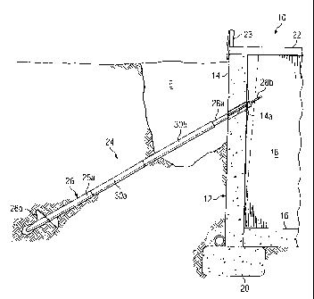
[0004] Fig. 1 is a partial sectional view of a building employing an anchoring
system
according to an embodiment of the present invention.
[0005] Fig. 2 is an enlarged isometric view depicting several components of
the
anchoring system of Fig. 1.
[0006] Figs. 3 and 4 are enlarged isometric views depicting two alternate
assemblies
for connecting components of the anchoring system of Fig. 1.
1
CA 02458103 2008-02-20
Detailed Description
[0007] Referring specifically to Fig. 1 and 2 of the drawings, the reference
numeral
refers, in general, to a building having an underground basement 12 formed, in
part,
by a vertical front wall 14, a floor, or horizontal, wall 16, and a vertical
side wall 18. The
front wall 14, and a portion of the floor 16 rest on a horizontal footer 20.
Although a
rear wall and another side wall are not shown, in a normal installation they
also would
be provided. The footer 20 extends underneath all of the vertical walls,
including the
front wall 12 and the side wall 18. The walls 14, and 18, the floor 16, and
the footer 20
all are formed of concrete.
[0008] It is understood that the remaining portion of the building 10 extends
above
the basement. This remaining, above-ground, portion of the building 10 is not
shown in
Fig. 2 with the exception of a portion of a floor 22 and a front wall 23, it
being
understood that the building would also include a rear wall, and two side
walls. In most
installations of this type, the exterior walls, including the wall 23, of the
above-ground
portion of the building 10 would normally be aligned with, and supported by,
the front
wall 14, the side wall 16, and the aforementioned rear wall and other side
wall of the
basement 12, respectively.
[0009] The system of the embodiment of Fig. 1 is designed to realign any
vertical
wall of the basement 10 that has deviated, or tilted, from a true vertical
position. For
the purpose of example, it. will be assumed that the front.wall 14 of the
basement has
deviated or tilted inwardly as shown by the phantom lines in Fig. 1, which
depict the
inner surface of the wall 14. In this case the system of the present invention
functions
to realign the wall 14 back to a true vertical position, and anchor the wall
in the latter
position.
[0010] To this end, the system of the embodiment of Fig. 1 includes an
assembly of
cylindrical members connected in an end-to-end relationship and referred to in
general.
by the reference numeral 24. The assembly 24 includes an auger section 26, a
connecting section 28, and two intermediate sections 30a and 30b. The auger
section
26 includes a tubular member 26a and a helical auger, or earth screw, 26b
mounted at
2
CA 02458103 2008-02-20
one end of the tubular member. Both of the intermediate sections 30a and 30b
are in
the form of tubular members, and the connecting section 28 includes a hollow
tubular
member 28a and an externally threaded shaft 28b extending from one end of the
latter
member. The corresponding ends of the intermediate section 30a and the auger
section 26; the corresponding ends of the intermediate sections 30a and 30b;
and the
corresponding ends of the intermediate section 30b and the connecting section
28 are
connected together in a manner to be described. The assembly 24 extends
through a
opening 14a extending through the wall 14a at an angle to the plane of the
wall, with
the auger 26 penetrating the ground outside the wall 14 and the threaded shaft
28b
extending inside the wall in the interior of the basement 12.
[0011] Referring to Fig. 2, a plate 32, having a central opening 32a formed
therethrough and two horizontally extending raised portions 32b and 32c, is
provided for
connecting the assembly 24 to the wall 14 (Fig. 1) in a manner to be
described. A
tapered anchor washer 34 having a central opening 34a formed therethrough is
provided for engaging the plate 36, along with a nut 36 sized to engage the
threaded
shaft 28b of the section 28.
[0012] Referring to Fig. 3, an apparatus for connecting the corresponding ends
of
the intermediate section 30a and the tubular member 26a of the auger section
26 is
referred to, in general, by the reference numeral 40. The apparatus includes
two ring-
shaped fasteners 42 and 44 each of which are both internally threaded and
externally
threaded. The corresponding end portions of the intermediate section 30a and
the
tubular member 26a are internally threaded so as to receive the fasteners 42
and 44,
respectively in a threaded engagement. An externally threaded rod 46 is
provided
which is sized to threadedly engage the latter threaded surfaces of each of
the
fasteners 42 and 44.
[0013] To connect the intermediate section 30a to the tubular member 26a, the
fasteners 42 and 44 are threadedly engaged in the corresponding end portions
of the
intermediate section 30a and the tubular member 26a, respectively, and thus
advance
into the sections until the respective faces of the fasteners at least extend
flush with the
3
CA 02458103 2008-02-20
respective ends of the sections. Then the respective end portions of the rod
46 :are
threadedly engaged in the fasteners 42 and 44. This can be done in sequence by
initially inserting one end of the rod 56 in one of the fasteners 42 or 44 and
rotating the
rod relative to the fastener, or vice versa, to advance the rod into the
fastener, and then
inserting the other end of the rod in the other fastener and rotating the rod
relatively to
the latter fastener, or vice versa. The amount of rotation is such that each
end portion
of the rod 46 extends through the fasteners 42 and 44, respectively, for an
axial length
sufficient to permit the corresponding ends of the latter sections to abut in
the
assembled condition shown in Fig. 1.
[0014] It is understood that the corresponding ends of the intermediate
sections 30a
and 30b, as well as the corresponding ends of the intermediate section 30b,
and the
tubular member 28a of the connecting section 28, are connected together in the
same
manner.
[0015] In operation, and assuming the front wall 14 has tilted, or deviated
from a true
vertical position, to a position shown by the phantom line in Fig. 1, an
excavation area E
is formed in the ground next to the wall 14 and the above-mentioned angled
opening
14a is drilled, or otherwise formed, through the wall 14. The section 30a is
passed
through the opening and the auger section 26 is connected to the section 30a
in the
excavation area E in the manner described above. A torque applying device (not
shown) is connected to the section 30a inside the basement 18 and activated to
apply
torque to the connected sections 30a and 26 so that the auger 26b penetrates
the
ground in response to the rotational movement. When the trailing end of the
section
30a in the basement 18 approaches the opening 14a, the section 30b is
connected to
the section 30a inside the basement in the manner described above and torque
applied to the section 30b. This continues with one or more additional
intermediate
sections (not shown) identical to the sections 30a and 30b until the auger 26
encounters sufficient resistance which can be determined in a conventional
manner.
The last connected intermediate section is then disconnected from the previous
intermediate section, which, in the example shown, is section 30b, and the
section 28 is
4
CA 02458103 2008-02-20
connected to the section 30b so that the section 28 extends through the
opening 14a.
The assembly 24 thus formed- extends at an angle to the wall 14 with the
magnitude of
the angle being determined by the angle of the opening 14a.
[0016] The end of the shaft 28a is then placed through the opening 32a of the
plate
32 and through the opening 34a of the washer 34 and the nut 36 is threadedly
engaged
with the latter end. Torque is then applied to the nut 36 in any known manner
while the
auger 26 anchors the other end portion of the assembly 24 in the ground. This
forces
the plate 32 against the inner surface of the wall 14 and then forces the
upper portion of
the wall in a direction from right-to-left, as viewed in Fig. 1, so that it
pivots, or tilts,
about its lower end. This tilting movement continues until the wall reaches a
true
vertical alignment as shown by the solid lines in Fig. 1. During this
application of torque
to the nut 36, the tapered washer 34 enables the nut to extend substantially
perpendicular to the axis of the shaft 28b so that the force is directed along
the axis of
the latter shaft.
[0017] In this connected position, the system 24 serves as an anchoring system
to
maintain the wall 14 in a true vertical alignment. It is understood that
additional
systems 24 can be placed, in a spaced relation, along the wall 14 and work
together in
unison to return the wall to a true vertical position and anchor the wall, in
the same
manner. The excavation E would then be filled in to complete the installation.
[0018] It is thus seen that the system 24 of the present invention enables a
wall to
be returned to a true vertical position and anchored in the latter position,
at a relatively
low expenditure of labor and expense. -
[0019] A connecting apparatus according to another embodiment is shown, in
general, by the reference numeral 50 in Fig. 4 and is also adapted to connect
the
corresponding ends of the intermediate section 30a and the tubular member 26a
of the
auger section 26. The system 50 comprises two fasteners 52 and 54, which are
sized
to extend in the corresponding end portions of the section 30a and the tubular
member
26a, respectively. The outer surface of each fastener 52 and 54 is hexagonal
in shape,
thus forming six planer surfaces and six angles, with the apexes of the angles
between
CA 02458103 2008-02-20
adjacent surfaces extending relative to the corresponding inner surfaces of
the section
30a and the tubular member 26a respectively, with minimal clearance.
[0020] The fasteners 52 and 54 are secured in the end portions of the section
30a
and the tubular member 26a with the respective outer faces of the fasteners at
least
extending flush with the corresponding ends of the sections. This can be done
in any
conventional manner such as by welding the outer planer surfaces of the
fasteners 52
and 54 to the corresponding inner surfaces of the section 30a and the tubular
member
26a. Each fastener 52 and 54 has an internally threaded bore, and an
externally
threaded rod 56, identical to the rod 46 of the previou.s embodiment, is
provided which
is sized to threadedly engage the bores of the fasteners. The section 30a and
the
tubular member 26a are thus connected in an end-to-end abutting relationship.
[0021] It is understood that the corresponding ends of the intermediate
sections 30a
and 30b, as well as the corresponding ends of the intermediate section 30b and
the
tubular member 28a of the connecting section 28 can be connected together by
the
apparatus 50 in the same manner.
Variations
[0022] The above embodiments are not limited to two intermediate sections 30a
and
30b; but rather, the number of intermediate sections can be varied depending
on the
depth in the ground that the auger section 26a has to penetrate in order to
attain
adequate support. Also, the wall that is returned to vertical and anchored in
the above
manner does not necessarily have to be below ground.
[0023] The fasteners 42, 44, 52 and 54 can be fastened into the interior of
the
tubular members 26a and 28a and the sections 30a and 30b by other techniques
utilizing other components, such as by adhesives, bolts, pins, clips, etc.
[0024] The outer surfaces of the fasteners 42, 44, 52 and 54 do not have to
extend
flush with the corresponding ends of the tubular members 26a and 28a and the
sections 30a and 30b but rather can extend in the sections a predetermined
distance.
[0025] Since other modifications, changes, and substitutions are intended in
the
foregoing disclosure, it is appropriate that the appended claims be construed
broadly
6
CA 02458103 2008-02-20
and in a manner consistent with the scope of the invention.
7