Language selection

Search

Patent 2458248 Summary

Third-party information liability

Some of the information on this Web page has been provided by external sources. The Government of Canada is not responsible for the accuracy, reliability or currency of the information supplied by external sources. Users wishing to rely upon this information should consult directly with the source of the information. Content provided by external sources is not subject to official languages, privacy and accessibility requirements.

Claims and Abstract availability

Any discrepancies in the text and image of the Claims and Abstract are due to differing posting times. Text of the Claims and Abstract are posted:

  • At the time the application is open to public inspection;
  • At the time of issue of the patent (grant).
(12) Patent Application: (11) CA 2458248
(54) English Title: HEATING SYSTEM
(54) French Title: SYSTEME DE CHAUFFAGE
Status: Deemed Abandoned and Beyond the Period of Reinstatement - Pending Response to Notice of Disregarded Communication
Bibliographic Data
(51) International Patent Classification (IPC):
  • F24F 03/048 (2006.01)
  • F24D 05/02 (2006.01)
  • F24H 03/06 (2006.01)
(72) Inventors :
  • LACELLE, JEAN-GUY (Canada)
(73) Owners :
  • JOCELYNE FOURNIER LACELLE
(71) Applicants :
  • JOCELYNE FOURNIER LACELLE (Canada)
(74) Agent: ROBERT WILLIAM WRAYWRAY, ROBERT WILLIAM
(74) Associate agent:
(45) Issued:
(22) Filed Date: 2004-02-18
(41) Open to Public Inspection: 2005-08-18
Availability of licence: N/A
Dedicated to the Public: N/A
(25) Language of filing: English

Patent Cooperation Treaty (PCT): No

(30) Application Priority Data: None

Abstracts

English Abstract


The present invention involves a radiator/hot water heating system (electric)
within a traditional
forced-air furnace housing, which is connected to the existing central air
ductwork of a building.
The radiator/hot water heating system uses a single radiator which is
connected to one or more
4" pipes through which water is heated by means of electricity. The entire
heating system
contains approximately 3 gallons of water. A fan circulates heat from the
radiator through-out the
building.


Claims

Note: Claims are shown in the official language in which they were submitted.

4
CLAIMS
The embodiments of the invention in which an exclusive property or privilege
is claimed are
defined as follows:
1. A radiator/hot water heating system comprising:
a pipe, said pipe containing water;
heating means positioned at one end of the pipe for heating the water within
the
pipe;
a radiator; said radiator connected to the pipe.
2. A radiator/hot water heating system comprising:
a pipe, said pipe containing water;
heating means positioned at each end of the pipe for heating the water within
the
pipe;
a radiator; said radiator connected to the pipe.
3. A radiator/hot water system according to claim 2, wherein said radiator/hot
water
system is contained within a housing, said housing connected to a ductwork
system
within a building, and including a fan for circulating heat from the radiator
through the
ductwork.
4. A radiator/hot water system according to claims 1, 2 or 3, wherein said
pipe is one or
more 4-inch pipes.
5. A radiator/hot water system according to claims 1, 2 or 3, wherein said
heating
means is an element 6000.
6. Each and every novel feature or novel combination of features herein
disclosed.

Description

Note: Descriptions are shown in the official language in which they were submitted.


CA 02458248 2004-02-18
1
HEATING SYSTEM
Field of the Invention
This invention relates to a heating system for use in buildings. In
particular; this invention relates
to a radiatorlhot water heating system which can use existing central air
ductwork..
Background of the Invention
Current methods of heating buildings, such as houses, include radiatorlhot
water systems which
use water to distribute heat. Water is heafied by a gas-fired boiler. A pump
drives the water
around a pipework loop via a series of radiators. Typically 40 gallons of
water or more is heated
and circulated through-out the house. One disadvantage of this system is the
I~ge volume of
water that must be heated, and the rapid dissipation of heat which occurs.
Another method of heating buildings is to use a forced air furnace system
where air is heated in
the furnace and circulated throughput the building via a series of ducts and
vents.
In many cases, consumers have discovered that the use of forced air furnaces
is too expensive,
inefficient, and environmentally unfriendly. Switching to a radiatorlhof water
system is preferred
but is impractical due to the existing central air ductwork which would need
to be replaced by
radiators.
It would be advantageous to develop a heating system which overcomes the
disadvantages of
the prior art.
Summary of the Invention
The present invention is for a radiatorJhot water heating system (electric)
within a traditional
forced-air furnace housing, which is connected-to the existing central air
ductwork of a building.
The radiator/hot water heating system uses a single radiator which is
connected to one or more
4° pipes through which water is heated by means of elearl~r. The entire
heating system
contains approximately 3 gallons of water. A fan circulates heat from the
radiator through-out the
building.
Advantages of the heating system include:

CA 02458248 2004-02-18
2
1 ) Only 3 gallons of water are used instead of the usual 40 gallons of water
in conventional
systems.
2) Cost savings occur because less water is heated.
3) One or more 4 " pipes are used to contain the 3 gallons of water instead of
a water tank.
4) The water can be heated using less wattage. Typically two 6 kw element 6000
are used.
5) When used in combination with an existing network of central air ductwork,
the air which has
been heated by the single radiator can be effectively moved throughout the
building.
Brief Description of the Drawins~s
Embodiments of the invention will now be described by way of example with
reference to the
following drawings and photographs in which:
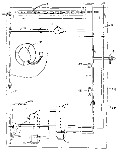
Fig. 1 is a schematic view of the system.
Detailed Description
Referring to Figure 1, there is a shown the heating system 28 according to one
embodiment of
the invention.
A radiator 2 has two pipes extending therefrom. One pipe 4 leads to a
circulating pump 6. The
circulating pump 6 circulates the water within the heating system 28. The
circulating pump 6 is
connected to the mid-point of a 1-inch pipe 8. This 1-inch pipe 8 is connected
at both ends to one
or more 4-inch pipes 10.
The 4-inch pipes 10 operates the same as a water tank in a more conventional
radiatdNhot water
system. The 4-inch pipes 10 contains all the water in the heating system 28,
except that which is
in circulation.
At one end of each 4-inch pipe is an element 6000 12 which is connected to an
electrical source
(not shown) to heat the water.
A small tank 16 is positioned at some point along the 4-inch pipe 10 to allow
for the expansion of
the water.

CA 02458248 2004-02-18
3
An air vent 18 is positioned at some point along the 1-inch pipe 8 to atlow
for the release of any
air which enters the heating system 28.
A temperature gauge 20 is positioned at some point along the 1-inch pipe 8 to
monitor and
regulate the temperature of the water.
A limiter 22 is posit'roned at some point along the 1-inch pipe 8 to control
the temperature of the
water.
Also shown is the intake pipe 26 or new or replacement water to the heating
system 28.
The entire heating system 28 is contained within a central forced air furnace
(non-electric)
housing 24 of a building. A fan 30 then circulates heat from the radiator 2
through-out the
building. There is no burner like you would find in a conventional forced air
furnace.
Ac~rding to ors; embodiment of this invention, only 3 gallons of water are
used instead of the
usual 40 gallons of water in conventional systems.
Cost savings occur because less water is heated.
One or more 4 " pipes are used to contain the 3 gallons of water instead of a
water tank.
The water can be heated using less wattage. . Typically two 6 kw element 6000
are used..
It will be understood that-modifications could be made without departing from
the scope of the
invention.

Representative Drawing
A single figure which represents the drawing illustrating the invention.
Administrative Status

2024-08-01:As part of the Next Generation Patents (NGP) transition, the Canadian Patents Database (CPD) now contains a more detailed Event History, which replicates the Event Log of our new back-office solution.

Please note that "Inactive:" events refers to events no longer in use in our new back-office solution.

For a clearer understanding of the status of the application/patent presented on this page, the site Disclaimer , as well as the definitions for Patent , Event History , Maintenance Fee  and Payment History  should be consulted.

Event History

Description Date
Inactive: IPC expired 2022-01-01
Inactive: Office letter 2007-03-14
Application Not Reinstated by Deadline 2007-02-19
Time Limit for Reversal Expired 2007-02-19
Letter Sent 2006-06-21
Reinstatement Requirements Deemed Compliant for All Abandonment Reasons 2006-05-23
Inactive: Transfer reinstatement 2006-05-23
Inactive: IPC from MCD 2006-03-12
Deemed Abandoned - Failure to Respond to Maintenance Fee Notice 2006-02-20
Application Published (Open to Public Inspection) 2005-08-18
Inactive: Cover page published 2005-08-17
Inactive: Status info is complete as of Log entry date 2005-07-08
Inactive: Abandoned - No reply to Office letter 2005-05-24
Inactive: IPC assigned 2004-06-07
Inactive: First IPC assigned 2004-06-04
Inactive: IPC assigned 2004-06-04
Amendment Received - Voluntary Amendment 2004-05-20
Inactive: Filing certificate - No RFE (English) 2004-03-24
Inactive: Courtesy letter - Evidence 2004-03-24
Application Received - Regular National 2004-03-24

Abandonment History

Abandonment Date Reason Reinstatement Date
2006-02-20

Fee History

Fee Type Anniversary Year Due Date Paid Date
Application fee - small 2004-02-18
Registration of a document 2006-05-23
Reinstatement 2006-05-23
2007-02-19
Owners on Record

Note: Records showing the ownership history in alphabetical order.

Current Owners on Record
JOCELYNE FOURNIER LACELLE
Past Owners on Record
JEAN-GUY LACELLE
Past Owners that do not appear in the "Owners on Record" listing will appear in other documentation within the application.
Documents

To view selected files, please enter reCAPTCHA code :


To view images, click a link in the Document Description column. To download the documents, select one or more checkboxes in the first column and then click the "Download Selected in PDF format (Zip Archive)" or the "Download Selected as Single PDF" button.

List of published and non-published patent-specific documents on the CPD .

If you have any difficulty accessing content, you can call the Client Service Centre at 1-866-997-1936 or send them an e-mail at CIPO Client Service Centre.


Document
Description 
Date
(yyyy-mm-dd) 
Number of pages   Size of Image (KB) 
Abstract 2004-02-17 1 13
Drawings 2004-02-17 1 44
Representative drawing 2005-07-20 1 12
Claims 2005-08-16 1 24
Description 2005-08-16 3 95
Filing Certificate (English) 2004-03-23 1 158
Request for evidence or missing transfer 2005-02-20 1 101
Courtesy - Abandonment Letter (Office letter) 2005-07-04 1 166
Reminder of maintenance fee due 2005-10-18 1 109
Courtesy - Abandonment Letter (Maintenance Fee) 2006-04-17 1 177
Notice of Reinstatement 2006-06-20 1 171
Courtesy - Certificate of registration (related document(s)) 2006-06-20 1 105
Correspondence 2004-03-23 2 52
Correspondence 2006-05-22 3 84
Correspondence 2007-03-13 1 21
Fees 2007-02-18 1 39