Language selection

Search

Patent 2458327 Summary

Third-party information liability

Some of the information on this Web page has been provided by external sources. The Government of Canada is not responsible for the accuracy, reliability or currency of the information supplied by external sources. Users wishing to rely upon this information should consult directly with the source of the information. Content provided by external sources is not subject to official languages, privacy and accessibility requirements.

Claims and Abstract availability

Any discrepancies in the text and image of the Claims and Abstract are due to differing posting times. Text of the Claims and Abstract are posted:

  • At the time the application is open to public inspection;
  • At the time of issue of the patent (grant).
(12) Patent Application: (11) CA 2458327
(54) English Title: GAS DEFLECTOR VALVE SET
(54) French Title: SOUPAPE DE DEFLECTEUR DE GAZ
Status: Deemed Abandoned and Beyond the Period of Reinstatement - Pending Response to Notice of Disregarded Communication
Bibliographic Data
(51) International Patent Classification (IPC):
  • F2M 26/26 (2016.01)
  • F1N 13/00 (2010.01)
  • F1P 7/10 (2006.01)
  • F16K 21/10 (2006.01)
  • F16K 21/12 (2006.01)
(72) Inventors :
  • IEDA, JOAO JOSE CARDINALI (Brazil)
(73) Owners :
  • WAHLER METALURGICA LTDA.
(71) Applicants :
  • WAHLER METALURGICA LTDA. (Brazil)
(74) Agent: MACRAE & CO.
(74) Associate agent:
(45) Issued:
(22) Filed Date: 2004-02-23
(41) Open to Public Inspection: 2004-08-27
Examination requested: 2009-02-23
Availability of licence: N/A
Dedicated to the Public: N/A
(25) Language of filing: English

Patent Cooperation Treaty (PCT): No

(30) Application Priority Data:
Application No. Country/Territory Date
PI 0300426-0 (Brazil) 2003-02-27

Abstracts

English Abstract


GAS DEFLECTOR VALVE SET, which is installed in the
engine cooling system before the inlet for the hot gas from the engine in
the water/gas heat exchanger of the EGR system. It has the purpose of
conducting the gas from the engine to the heat exchanger of the EGR
system when its temperature is above normal and its cooling is required,
or to recycle it directly to the engine, without it passing through the heat
exchanger when the gas temperature is below the minimum limits for
cooling. The gas deflector valve set is activated by a pneumatic system
(vacuum or pressure) by means of a directed valve actuated by an
electric signal from engine's electronic center and control.


Claims

Note: Claims are shown in the official language in which they were submitted.

5
CLAIMS
1. GAS DEFLECTOR VALVE SET, characterized by a flat
block (1) designed with two adjacent circular holes (2) and (3) that
define the passages of the gas, with a lower projection (4) at one end
and with the other end coupled to the support (5) of the vacuum or
pressure pneumatic valve (6), equipped with nipple (7) for connecting
the system hose and subject to the action of a draw spring (8); and for
having in one of the circular holes (2) an upper through hole and a lower
through hole, to which the roller bearings or bushings (9) are assembled
for installation of a shaft (10) perpendicular to the gas current, whose
lower terminal penetrates said lower hole and comes out at the bottom
part of the block (1), where it is connected to a plate (11) having two
upper lips (12) at the ends that act as limiter of the rotary motion, with
angular definition, of this plate (11) on reaching one or the other side of
the projection (4) of the block; and for having in the interior of the
opening (2) and riveted to the shaft (10) an element for
blocking/releasing the gas passage, defined by a "butterfly" valve (13);
and having an axial rod (14) incorporated to the pneumatic actuator (6)
that extends throughout the lower length of the block (1 ) and is
articulated at its end to the plate (11 ), whose point of articulation is
eccentric to the point of connection of the shaft (10), and therefore said
rod (14) works as a connecting rod, converting the rectilinear motion of
said shaft (10) into circular motion.

6
2. GAS DEFLECTOR VALVE SET, according to claim 1,
characterized by a version in which the element for blocking/releasing
the gas passage, or "butterfly" valve (13a), is installed in the second
circular opening (3) of the block, where the upper and lower through
holes are located, with bearings or bushings (9a) to reduce friction on
the shaft (10a) perpendicular to the gas current and to which said
"butterfly' valve (13a) is fixed, being that, in this case, the axial rod
(14a)
of the vacuum or pressure pneumatic actuator (6) is shorter and extends
up to the middle of the length of the block (1), where the latter is
provided with a shoulder (15) that acts as a top to limit the circular
motion, with angular definition, of the plate (11a) on reaching one or
another upper lip (12a) of the plate.

Description

Note: Descriptions are shown in the official language in which they were submitted.


CA 02458327 2004-02-23
1
"GAS DEFLECTOR VALVE SET"
This patent pertains to the Invention of a Gas Deflector
Valve Set, for use in the automobile industry, with the main purpose of
conducting gas through the heat exchanger/gas cooler when cooling is
required and, when the gas is below the minimum limits for cooling,
recycling the gas directly to the engine, without it passing through the
heat exchanger.
This gas deflector valve set is activated by a vacuum or
pressure pneumatic system by means of a directed valve actuated by an
electric signal from the engine's electronic center and control.
Application of the gas deflector valve in reference secures
gas recycling at an adequate temperature; improves and secures the
performance of internal combustion engines as regards combustion,
specific power, specific consumption, transience of operation and control
of pollutant emission; reduces the occurrence of gas condensation and,
consequently, non-operation of components and accessories of the
system for control of pollutant emission, due to soot, oil, water deposits,
and other residues from combustion on the walls of equipment, heat
exchanger, ducts and EGR valve, inlet manifold, nipples and other
components.
In order to have a clear picture of the gas deflector valve set
in question, follow the attached illustrative drawings, which should be
referred to for better understanding of the detailed description below.
This gas deflector valve set is presented in two versions,
different only in the location of the element for blocking/releasing
(butterfly valve) the gas passage. Thus:

CA 02458327 2004-02-23
2
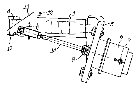
FIGURE 1 shows the lower view of the gas deflector valve
set, first version;
FIGURE 2 shows a plan view of the gas deflector valve set,
first version;
FIGURE 3 shows the lower view of the gas deflector valve
set, second version;
FIGURE 4 shows a plan view of the gas deflector valve set,
second version;
FIGURE 5 shows a scheme of the engine cooling system,
with the gas deflector valve set of this patent.
As can be inferred from figures 1 and 2, the first version of
the gas deflector valve set proposed is characterized essentially by a flat
block (1 ) with special peripheral configuration, with two adjacent circular
openings (2) and (3) which define the gas passages, with a lower
projection (4) at one end at the opposite end coupled to the support (5)
of the vacuum or pressure pneumatic valve (6), equipped with nipple (7)
for connecting the system hose and subject to the action of a draw
spring (8).
One of the circular openings (2) has an upper through hole
and a lower through hole, to which roller bearings or bushings (9) are
assembled for installation of a shaft (10) perpendicular to the gas
current, whose lower terminal penetrates said lower hole and comes out
in the lower part of the block (1 ), where the end of this shaft (10) is
connected to a plate (11 ) equipped at the ends with two upper lips (12)
that act as limiters of the rotary motion, with angular definition, of this

CA 02458327 2004-02-23
3
plate of this plate (11 ) on reaching one or another side of the block's
extension (4).
In the interior of the opening (2) and riveted to the shaft (10)
is an element for blocking/releasing the gas passage, defined by a
"butterfly" valve (13).
Incorporated to the actuator (6) is an axial rod (14) extending
throughout the lower length of the block (1 ). The end of this rod (14) is
articulated to the plate (11 ), whose point of articulation is eccentric to
the
point of connection of the shaft (10), and therefore, this rod (14) works
as a connecting rod, converting the rectilinear motion of the shaft (10)
into circular motion.
The second version of the gas deflector valve set (figures 3
and 4) presents small differences in relation to the first version, such as
the fact that the element for blocking/releasing the gas passage, or the
"butterfly valve" (13a), is installed in the second circular opening (3) of
the block, where the upper and lower through holes are located, with
bearings or bushings (9a) to reduce friction on the shaft (10a)
perpendicular to the gas current and to which the "butterfly" valve (13a)
is riveted. In this case, the axial rod (14a) of the vacuum or pressure
pneumatic valve (6) is shorter and extends up to the middle of the block
(1 ) length, where the latter has a shoulder (15) that acts as a top to limit
the circular motion, with angular definition, of the plate (11a) on reaching
one or another upper lip (12a) of the plate. The working is identical to
that of the first version.
Figure 5 shows a scheme of the engine cooling system, with
the gas deflector valve set which, as can be seen, is installed before the

CA 02458327 2004-02-23
4
inlet of the hot gas of the engine in the gas/water heat exchanger of the
EGR system.
Thus, with the inclusion of the gas deflector set, the gas from
the engine is only conducted to the heat exchanger of the EGR system
when its temperature is above normal and its cooling is required (the
"butterfly" valve is opened by action of the pneumatic actuator in such a
way that the passage of the gas is released toward the heat exchanger
of the EGR system). And when the gas temperature is below the
minimum limits for cooling, the gas is recycled directly to the engine,
without passing through the heat exchanger (the "butterfly" valve is
activated by pneumatic actuation in such a way as to cause blocking
and unblocking and the respective direction of flow, which depends on
the circuit and layout of the systems for cooling and control of emission
from the internal combustion engines.
Thus, this gas deflector valve set fully satisfies the proposed
objectives, performing the functions for which it was designed in a
practical and efficient manner, providing a series of advantages inherent
to its applicability, and giving it unique and innovative features
possessing the fundamental requirements for novelty.

Representative Drawing
A single figure which represents the drawing illustrating the invention.
Administrative Status

2024-08-01:As part of the Next Generation Patents (NGP) transition, the Canadian Patents Database (CPD) now contains a more detailed Event History, which replicates the Event Log of our new back-office solution.

Please note that "Inactive:" events refers to events no longer in use in our new back-office solution.

For a clearer understanding of the status of the application/patent presented on this page, the site Disclaimer , as well as the definitions for Patent , Event History , Maintenance Fee  and Payment History  should be consulted.

Event History

Description Date
Inactive: IPC deactivated 2021-10-09
Inactive: First IPC assigned 2019-05-16
Inactive: IPC assigned 2019-05-16
Inactive: IPC expired 2016-01-01
Inactive: IPC deactivated 2011-07-29
Time Limit for Reversal Expired 2011-02-23
Application Not Reinstated by Deadline 2011-02-23
Deemed Abandoned - Failure to Respond to Maintenance Fee Notice 2010-02-23
Inactive: IPC expired 2010-01-01
Inactive: IPC assigned 2010-01-01
Letter Sent 2009-04-14
All Requirements for Examination Determined Compliant 2009-02-23
Request for Examination Received 2009-02-23
Request for Examination Requirements Determined Compliant 2009-02-23
Inactive: IPC from MCD 2006-03-12
Letter Sent 2005-04-18
Inactive: Single transfer 2005-03-09
Application Published (Open to Public Inspection) 2004-08-27
Inactive: Cover page published 2004-08-26
Inactive: First IPC assigned 2004-06-03
Inactive: IPC assigned 2004-06-03
Inactive: Courtesy letter - Evidence 2004-03-30
Application Received - Regular National 2004-03-24
Inactive: Filing certificate - No RFE (English) 2004-03-24

Abandonment History

Abandonment Date Reason Reinstatement Date
2010-02-23

Maintenance Fee

The last payment was received on 2009-02-23

Note : If the full payment has not been received on or before the date indicated, a further fee may be required which may be one of the following

  • the reinstatement fee;
  • the late payment fee; or
  • additional fee to reverse deemed expiry.

Patent fees are adjusted on the 1st of January every year. The amounts above are the current amounts if received by December 31 of the current year.
Please refer to the CIPO Patent Fees web page to see all current fee amounts.

Fee History

Fee Type Anniversary Year Due Date Paid Date
Application fee - standard 2004-02-23
Registration of a document 2005-03-09
MF (application, 2nd anniv.) - standard 02 2006-02-23 2005-11-30
MF (application, 3rd anniv.) - standard 03 2007-02-23 2007-02-23
MF (application, 4th anniv.) - standard 04 2008-02-25 2008-02-22
MF (application, 5th anniv.) - standard 05 2009-02-23 2009-02-23
Request for examination - standard 2009-02-23
Owners on Record

Note: Records showing the ownership history in alphabetical order.

Current Owners on Record
WAHLER METALURGICA LTDA.
Past Owners on Record
JOAO JOSE CARDINALI IEDA
Past Owners that do not appear in the "Owners on Record" listing will appear in other documentation within the application.
Documents

To view selected files, please enter reCAPTCHA code :


To view images, click a link in the Document Description column (Temporarily unavailable). To download the documents, select one or more checkboxes in the first column and then click the "Download Selected in PDF format (Zip Archive)" or the "Download Selected as Single PDF" button.

List of published and non-published patent-specific documents on the CPD .

If you have any difficulty accessing content, you can call the Client Service Centre at 1-866-997-1936 or send them an e-mail at CIPO Client Service Centre.

({010=All Documents, 020=As Filed, 030=As Open to Public Inspection, 040=At Issuance, 050=Examination, 060=Incoming Correspondence, 070=Miscellaneous, 080=Outgoing Correspondence, 090=Payment})


Document
Description 
Date
(yyyy-mm-dd) 
Number of pages   Size of Image (KB) 
Abstract 2004-02-22 1 22
Description 2004-02-22 4 172
Claims 2004-02-22 2 67
Drawings 2004-02-22 3 65
Representative drawing 2004-06-03 1 10
Filing Certificate (English) 2004-03-23 1 158
Request for evidence or missing transfer 2005-02-23 1 101
Courtesy - Certificate of registration (related document(s)) 2005-04-17 1 104
Reminder of maintenance fee due 2005-10-24 1 109
Reminder - Request for Examination 2008-10-26 1 127
Acknowledgement of Request for Examination 2009-04-13 1 176
Courtesy - Abandonment Letter (Maintenance Fee) 2010-04-19 1 172
Correspondence 2004-03-23 1 25