Language selection

Search

Patent 2458491 Summary

Third-party information liability

Some of the information on this Web page has been provided by external sources. The Government of Canada is not responsible for the accuracy, reliability or currency of the information supplied by external sources. Users wishing to rely upon this information should consult directly with the source of the information. Content provided by external sources is not subject to official languages, privacy and accessibility requirements.

Claims and Abstract availability

Any discrepancies in the text and image of the Claims and Abstract are due to differing posting times. Text of the Claims and Abstract are posted:

  • At the time the application is open to public inspection;
  • At the time of issue of the patent (grant).
(12) Patent Application: (11) CA 2458491
(54) English Title: SIGNALING DEVICE FOR SIGHTING SYSTEMS, FOR EXAMPLE FOR RESCUE CRAFTS IN THE NAUTICAL FIELD AND THE LIKE
(54) French Title: DISPOSITIF DE SIGNALISATION POUR SYSTEMES DE VISEE, PAR EXEMPLE POUR LES EMBARCATIONS DE SAUVETAGE DANS LE DOMAINE MARITIME
Status: Deemed Abandoned and Beyond the Period of Reinstatement - Pending Response to Notice of Disregarded Communication
Bibliographic Data
(51) International Patent Classification (IPC):
  • F21L 4/02 (2006.01)
  • B63B 45/04 (2006.01)
  • B63C 9/20 (2006.01)
  • F21S 9/02 (2006.01)
(72) Inventors :
  • AGUGLIA, JORGE MIGUEL (Italy)
(73) Owners :
  • S.I.E.M. S.R.L.
(71) Applicants :
  • S.I.E.M. S.R.L. (Italy)
(74) Agent: NORTON ROSE FULBRIGHT CANADA LLP/S.E.N.C.R.L., S.R.L.
(74) Associate agent:
(45) Issued:
(22) Filed Date: 2004-02-24
(41) Open to Public Inspection: 2004-11-06
Examination requested: 2009-02-24
Availability of licence: N/A
Dedicated to the Public: N/A
(25) Language of filing: English

Patent Cooperation Treaty (PCT): No

(30) Application Priority Data:
Application No. Country/Territory Date
03425288.2 (European Patent Office (EPO)) 2003-05-06

Abstracts

English Abstract


A signaling device for sighting systems, for example for rescue crafts in
the nautical field and the like, comprising at least two lamps arranged so
that their respective filaments are mutually perpendicular, so as to achieve a
circular luminous emission that is uniform over 360°.


Claims

Note: Claims are shown in the official language in which they were submitted.

5
THE EMBODIMENTS OF THE INVENTION IN WHICH AN EXCLUSIVE
PROPERTY OR PRIVILEGES IS CLAIMED ARE DEFINED AS FOLLOWS:
1. A signaling device for sighting systems, comprising: at least two
lamps having respective filaments thereof arranged mutually perpendicular,
so as to achieve a circular luminous emission that is uniform over a
360°
emission field.
2. The device of claim 1, further comprising a signaling means and a
body that is suitable to be connected externally to a rescue craft and to
accommodate power supply means, said body being connected to the
signaling means by way of a connecting cable, and wherein said signaling
means comprise said at least two lamps, arranged with the respective
filaments thereof mutually perpendicular, so as to obtain a circular luminous
emission that is uniform over a 360° emission field.
3. The device of claim 1, wherein said at least two lamps are incandescent
lamps.
4. The device of claim 2, comprising a protection dome; said at least two
lamps being accommodated within said dome that is made of a material
transparent to light.
5. The device of claim 2, wherein said body is provided with switch
means comprising a cord that is wound around the switch means for
automatic actuation thereof upon opening of the rescue craft.
6. The device of claim 4, wherein said dome made of light-transparent
material is provided, in a downward region, with a flange for fixing to an
outer surface of said rescue craft.
7. The device of claim 6, wherein said at least two lamps are arranged
substantially at the center of said dome made of light-transparent material.
8. The device of claim 4, wherein said body suitable to accommodate
power supply means and said dome in which said at least two lamps are
accommodated are mutually connected by way of said connecting cable
with a hermetic sealed connector interposed.

Description

Note: Descriptions are shown in the official language in which they were submitted.


CA 02458491 2004-02-24
1
The present invention relates to a signaling device for sighting systems,
for example for rescue crafts in the nautical field and the like. More
particularly, the invention relates to an intermittent signaling device.
As is known, external signaling devices suitable to be used for rescue
crafts such as life rafts for watercraft are currently commercially available.
However, these signaling devices have a light distribution system that is
provided by using a single lamp whose brightness, emitted by the single
filament of the lamp, produces a given light field, leaving substantially
uncovered two sectors in which shadow zones are formed.
Essentially, with a single filament and therefore a single lamp, two
substantially opposite lighting regions are produced which extend from the
body of the lamp, with two shadow sectors that are located at the respective
north and south poles when one considers a sphere whose light field is
determined by the lighting of the lamp.
This is of course a drawback in signaling devices that must be used in
sighting systems, for example for rescue crafts, in which the primary
purpose is obviously to be sighted at the greatest possible distance so as to
allow the recovery of shipwrecked persons.
Accordingly, existing signaling devices, despite being accepted and
commonly used by users, do not offer the assurances of reliability that make
the signaling device absolutely suitable for use in the nautical field.
Furthermore, if the single filament breaks, the device is unusable and
therefore the rescue system is no longer available.
The aim of the present invention is to provide a signaling device for
sighting systems, for example for rescue crafts, that allows to provide
lighting over a field of substantially 360°, without leaving unwanted
shadow zones.
3o Within this aim, an object of the present invention is to provide a

CA 02458491 2004-02-24
2
signaling device that allows more effective sighting from a distance of the
life raft or rescue craft on which the signaling device is fitted.
Another object of the present invention is to provide a signaling device
that can be used outside the raft.
Another object of the present invention is to provide a signaling device
that is highly reliable, relatively simple to manufacture, and at competitive
costs.
This aim and these and other objects that will become better apparent
hereinafter are achieved by a signaling device for sighting systems, for
example for rescue crafts in the nautical field and the like, characterized in
that it comprises at least two Iamps arranged so that their respective
filaments are mutually perpendicular, so as to achieve a circular luminous
emission that is uniform over 360°.
Further characteristics and advantages of the invention will become
better apparent from the description of a preferred but not exclusive
embodiment of the device according to the present invention, illustrated by
way of non-limitative example in the accompanying drawings, wherein:
Figure 1 is a perspective view of the signaling device according to the
present invention; and
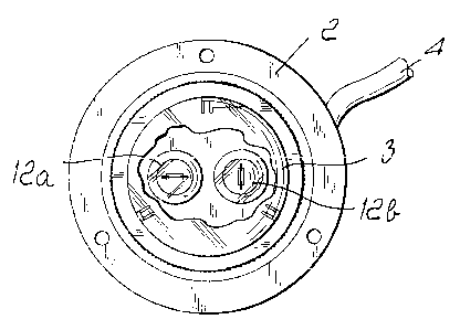
Figure 2 is a top plan view of the arrangement of the lamps of the
signaling device according to the present invention.
With reference to the figures, the signaling device according to the
present invention, generally designated by the reference numeral 10,
comprises a body l, which contains batteries for supplying power to the
device and is suitable to be fixed to a life raft by means of a pair of
lateral
supports 11.
The body of the signaling device is then connected to a cylindrical body
2 provided with a fixing flange for the connection of the body 2 to the

CA 02458491 2004-02-24
J
outside of the group rescue craft.
The hermetic closure of the body 2 occurs by means of a dome 3, inside
which at least two lamps 12a and 12b are respectively accommodated; the
arrangement of said lamps is explained hereinafter.
The dome 3 is preferably made of polycarbonate, so as to transmit light
on the entire upper hemisphere, and is provided in a downward region with
a flange for fixing to the outer surface of the rescue craft.
The body 2 and the body 1 are connected by means of a cable 4 and a
sealed connector 5 of the hermetic type. This kind of connection facilitates
both installation during the assembly of the lamp and the replacement of the
battery pack accommodated within the body 1.
Conveniently, a power-on switch 6, arranged at the top of the body 1 for
accommodating the battery pack, is provided in order to switch on and off
the lighting device. The switch 6 is conveniently of the mechanical rotary
type, and in the case of automatically inflatable raft the switch 6 is
provided
with a receptacle that allows to wind up an actuation cord 7 that is provided
with a ring 8 at one end. The automatic opening of the raft pulls the cord 7,
which in turn rotates the switch 6, causing the automatic lighting of the
lamps 12a and 12b accommodated within the dome 3.
The body 2 also accommodates, in addition to the lamps of the signaling
device, the electronic control circuit.
A particularity of the invention consists of the fact that the lamps 12a and
12b arranged within the dome 3 are located at the center of the dome so that
their respective filaments are arranged substantially at right angles to each
other. This allows to improve the emission of light over the entire upper
hemisphere, lighting the shadow zones that are typical of known types of
lighting device, and also increases the reliability of the device. With two
lamps, the probability that they both fail simultaneously is extremely low.
Preferably, the lamps 12a and 12b are of the incandescent type:
The arrangement of the two lamps at right angles to each other therefore

CA 02458491 2004-02-24
w
0
4
allows to solve the drawback of shadow zones produced by using a single
lamp like the known type of device.
Conveniently, it is also possible to use more than two lamps, always
arranging them however with their filaments at right angles to each other, so
as to cover over 360° the entire upper hemisphere without resorting to
the
use of lenses that can provide the same result by means of an optical effect.
Furthermore, the use of two lamps simultaneously, for an equal power
level, allows to have an increase in luminous intensity or, for an equal
luminous intensity, a longer reuse endurance.
The provision of a circular light emission that is uniform over
360° is
fundamental, since in emergency situations and specifically in the case of
searches at sea, the success of the rescue operation can be determined by the
sighting of the life raft in the shortest possible time, in order to be able
to
rescue the shipwrecked persons.
In practice it has been found that the device according to the present
invention fully achieves the intended aim and objects.
The device thus conceived is susceptible of numerous modifications and
variations, a.ll of which are within the scope of the appended claims.
All the details may further be replaced with other technically equivalent
2o elements. In, practice, the materials used, as well as the contingent
shapes
and dimensions, may be any according to requirements and to the state of
the art.

Representative Drawing
A single figure which represents the drawing illustrating the invention.
Administrative Status

2024-08-01:As part of the Next Generation Patents (NGP) transition, the Canadian Patents Database (CPD) now contains a more detailed Event History, which replicates the Event Log of our new back-office solution.

Please note that "Inactive:" events refers to events no longer in use in our new back-office solution.

For a clearer understanding of the status of the application/patent presented on this page, the site Disclaimer , as well as the definitions for Patent , Event History , Maintenance Fee  and Payment History  should be consulted.

Event History

Description Date
Application Not Reinstated by Deadline 2012-02-24
Time Limit for Reversal Expired 2012-02-24
Deemed Abandoned - Failure to Respond to Maintenance Fee Notice 2011-02-24
Letter Sent 2009-04-15
Request for Examination Received 2009-02-24
Request for Examination Requirements Determined Compliant 2009-02-24
All Requirements for Examination Determined Compliant 2009-02-24
Inactive: IPC from MCD 2006-03-12
Inactive: Filing certificate - No RFE (English) 2004-12-16
Application Published (Open to Public Inspection) 2004-11-06
Inactive: Cover page published 2004-11-05
Inactive: IPC assigned 2004-06-04
Inactive: First IPC assigned 2004-06-04
Inactive: Filing certificate correction 2004-05-19
Inactive: Correspondence - Formalities 2004-05-19
Inactive: Filing certificate - No RFE (English) 2004-03-25
Filing Requirements Determined Compliant 2004-03-25
Letter Sent 2004-03-25
Application Received - Regular National 2004-03-25

Abandonment History

Abandonment Date Reason Reinstatement Date
2011-02-24

Maintenance Fee

The last payment was received on 2010-02-22

Note : If the full payment has not been received on or before the date indicated, a further fee may be required which may be one of the following

  • the reinstatement fee;
  • the late payment fee; or
  • additional fee to reverse deemed expiry.

Please refer to the CIPO Patent Fees web page to see all current fee amounts.

Fee History

Fee Type Anniversary Year Due Date Paid Date
Registration of a document 2004-02-24
Application fee - standard 2004-02-24
MF (application, 2nd anniv.) - standard 02 2006-02-24 2006-02-01
MF (application, 3rd anniv.) - standard 03 2007-02-26 2007-02-08
MF (application, 4th anniv.) - standard 04 2008-02-25 2008-02-08
MF (application, 5th anniv.) - standard 05 2009-02-24 2009-02-17
Request for examination - standard 2009-02-24
MF (application, 6th anniv.) - standard 06 2010-02-24 2010-02-22
Owners on Record

Note: Records showing the ownership history in alphabetical order.

Current Owners on Record
S.I.E.M. S.R.L.
Past Owners on Record
JORGE MIGUEL AGUGLIA
Past Owners that do not appear in the "Owners on Record" listing will appear in other documentation within the application.
Documents

To view selected files, please enter reCAPTCHA code :


To view images, click a link in the Document Description column. To download the documents, select one or more checkboxes in the first column and then click the "Download Selected in PDF format (Zip Archive)" or the "Download Selected as Single PDF" button.

List of published and non-published patent-specific documents on the CPD .

If you have any difficulty accessing content, you can call the Client Service Centre at 1-866-997-1936 or send them an e-mail at CIPO Client Service Centre.


Document
Description 
Date
(yyyy-mm-dd) 
Number of pages   Size of Image (KB) 
Description 2004-02-24 4 221
Abstract 2004-02-24 1 19
Drawings 2004-02-24 1 35
Claims 2004-02-24 1 61
Representative drawing 2004-09-02 1 15
Cover Page 2004-10-14 1 39
Courtesy - Certificate of registration (related document(s)) 2004-03-25 1 105
Filing Certificate (English) 2004-03-25 1 159
Courtesy - Certificate of registration (related document(s)) 2004-03-25 1 106
Filing Certificate (English) 2004-12-16 1 158
Reminder of maintenance fee due 2005-10-25 1 109
Reminder - Request for Examination 2008-10-27 1 128
Acknowledgement of Request for Examination 2009-04-15 1 176
Courtesy - Abandonment Letter (Maintenance Fee) 2011-04-21 1 173
Correspondence 2004-05-19 3 127