Language selection

Search

Patent 2459248 Summary

Third-party information liability

Some of the information on this Web page has been provided by external sources. The Government of Canada is not responsible for the accuracy, reliability or currency of the information supplied by external sources. Users wishing to rely upon this information should consult directly with the source of the information. Content provided by external sources is not subject to official languages, privacy and accessibility requirements.

Claims and Abstract availability

Any discrepancies in the text and image of the Claims and Abstract are due to differing posting times. Text of the Claims and Abstract are posted:

  • At the time the application is open to public inspection;
  • At the time of issue of the patent (grant).
(12) Patent Application: (11) CA 2459248
(54) English Title: INJECTION BLOW MOULDING APPARATUS FOR PRODUCING BIAXIAL ORIENTATED THERMOPLASTIC CONTAINERS
(54) French Title: APPAREIL DE MOULAGE PAR INJECTION-SOUFFLAGE ADAPTE A LA PRODUCTION DE CONTENANTS THERMOPLASTIQUES BI-ORIENTES
Status: Deemed Abandoned and Beyond the Period of Reinstatement - Pending Response to Notice of Disregarded Communication
Bibliographic Data
(51) International Patent Classification (IPC):
  • B29C 49/06 (2006.01)
  • B29C 49/12 (2006.01)
(72) Inventors :
  • ARAUJO, PAULO JULIANO PEREIRA DA SILVA (Portugal)
  • SANTOS, ANTONIO PEREIRA (Portugal)
(73) Owners :
  • PLASDAN-MAQUINAS PARA PLASTICOS LD
(71) Applicants :
  • PLASDAN-MAQUINAS PARA PLASTICOS LD (Portugal)
(74) Agent: BATTISON WILLIAMS DUPUIS
(74) Associate agent:
(45) Issued:
(86) PCT Filing Date: 2002-02-11
(87) Open to Public Inspection: 2003-08-21
Examination requested: 2004-03-01
Availability of licence: N/A
Dedicated to the Public: N/A
(25) Language of filing: English

Patent Cooperation Treaty (PCT): Yes
(86) PCT Filing Number: PCT/PT2002/000003
(87) International Publication Number: PT2002000003
(85) National Entry: 2004-03-01

(30) Application Priority Data: None

Abstracts

English Abstract


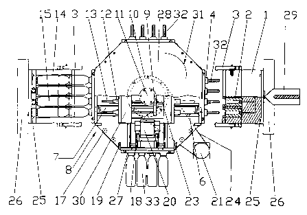
The present invention refers to an Integrated Injection-Stretch-Blow Mold
suitable for producing bi-orientated thermoplastics containers, which can be
installed in an injection molding machine, occupying the space normally
destined for injection molds. It consists of a central chassis (8) having in
its interior a central block mechanism (30), with the injection cores (6),
blow cores (12) and the mechanisms for stretch and blow (9, 13, 23) and for
release of the finish containers (18, 20); a motorized rotating system (31),
connected to the central block mechanism (30), by a rotating plate shaft (11),
for the transport of the performs between at least an injection mold (1) and a
blow mold (14) placed around the central chassis (8).


French Abstract

La présente invention concerne un appareil intégré de moulage par injection-soufflage avec bi-étirage adapté à la production de contenants thermoplastiques bi-orientés. Cet appareil peut être installé dans une machine de moulage par injection à l'emplacement destiné habituellement aux moules d'injection. Il se compose d'un châssis central (8) comportant un mécanisme central de type bloc (30) auquel sont fixés les noyaux d'injection (6), les noyaux de soufflage (12), ainsi que les mécanismes de soufflage avec bi-étirage (9, 13, 23) et d'éjection des contenants finis (18, 20). Un mécanisme rotatif motorisé (31), couplé au mécanisme central de type bloc (30) par l'intermédiaire d'un arbre à plateaux rotatifs (11), sert à transporter les préformes entre au moins un moule d'injection (1) et un moule de soufflage (14) placés autour du châssis central (8).

Claims

Note: Claims are shown in the official language in which they were submitted.


5
CLAIMS
1-INTEGRATED MOLD FOR THE PRODUCTION OF CONTAINERS IN BI-
ORIENTATED THERMOPLASTICS, characterized by the fact, that it can be installed
in
an injection molding machine, occupying the space normally destined for
injection molds
and comprising a central chassis (8), around which are at least one injection
mold and one
stretch-blow mold are placed; The central chassis (8) comprises a central
block mechanism
(30) where the injection and blow cores, the ejection and the stretch-blow
mechanism (9,
13, 23) are attached; In the central chassis (8) and mounted on two rotating
plate shafts (11)
of the central block mechanism (30) is a motorized rotating mechanism (31),
consisting of
two rotating plates (28), to transport the preforms from one position to
another, on the
periphery of the central chassis (8); As the rotating plates (28) are fixed
via the rotating
plate tie-bars (17) and have on their interior surface sliding bass (7) of the
preform carrier
plates (27) and carrier plate opening limit cams (19), to open the latches
(3), placed on both
the injection and blow molds, that drag the preform carrier plates (27) during
the opening of
the integrated mold to the edge of the rotating plates (28), where they are
then in the
position to transport the preforms, during the productive cycle, which, while
explanatory
and simplified, starts after the mounting and positioning of the integrated
mould in the
totally open position, as shown in figures 1 and 2, with the preform carrier
plates (27) ready
for preform transport and with all the cavities and preform Garner plates (27)
empty; After
the lateral closing of the blow mold, the injection molding machine then
closes its platens
and concludes the total closing of the integrated mold, as shown in Figures 3
and 4; at this
point, the molten plastic is injected into the injection mold forming the
first set of preforms,
once the preforms are solid, the machine platens move and the INTEGRATED MOLD
is
fully open, with the performs positioned for transport on the edge of the
Rotating Plates
(28); now starts the movement of the Rotating Mechanism (31), in a
synchronized way, and
the first set of preforms goes to an intermediate waiting position, between
the injection and
blow molds; the INTEGRATED MOLD is again completely closed, so that a second
set of
preforms is injected in the injection mold, again total opening of the
INTEGRATED
MOLD and rotation, after this the first set of preforms are placed in front of
the blow mold;
total close of the INTEGRATED MOLD and a third set of preforms are injected
whilst at
the same time the first set of preforms are being stretched and blown, as
illustrated in
figures 3 and 4, so that the finished containers can be obtained; again total
opening of the
INTEGRATED MOLD, the rotation system (31) is again rotated causing the first
set of
finished containers to be placed at the ejection position; Again the
integrated mold is
completely closed, and ejection of the finished containers is carried out in
parallel with the
injection of the fourth set of preforms and the stretch-blow of the second set
of preforms;
After a new opening stroke and rotation cycle the now empty preform carrier
plates (27) are
placed in front of the injection mold, so that after the next closing of the
INTEGRATED
MOLD a new production cycle starts and the process repeats, injection, stretch-
blow,
ejection, opening, rotation and so on successively.

Description

Note: Descriptions are shown in the official language in which they were submitted.


CA 02459248 2004-03-O1
WO 03/068483 PCT/PT02/00003
INJECTION BLOW MOULDING APPARATUS FOR PRODUCING BIAXIAL ORIENTATED
THERMOPLASTIC CONTAINERS
DESCRIPTION
The present invention refers to a mold suitable for producing containers in
P.E.T.
(Polyethylene terephthalate), P.V.C. (Polyvinyl chloride), P.P.
(Polypropylene) and other
bi-orientated thermoplastics, by injection-stretch-blow molding.
The process of producing containers in bi-orientated thermoplastics, namely in
P.E.T, have
as common designation, molding b~injection-stretch-blow. The process is
accomplished
using machines that are simultaneously capable of injection and stretch-blow
molding, or in
two independent machines, one being of injection and the other of stretch-
blow, that do not
necessarily have to be at the same location.
The molding process by injection-stretch-blow starts with an intermediate
molding of the
container, designated preform, in an injection mold, through the process of
molding by
injection. As a second step (which can be separated), the preform that is at
an adequate
temperature is mechanically stretched and blown in the blow-mold, causing the
container to
acquire its final form. This process of molding, of which the production of
containers in
P.E.T. and other thermoplastics are associated, is the combination of two
processes,
offering the best benefits of both. In this way the containers are bi-axially
extended which
guarantees characteristics of impact strength, stiffness, transparency and
surface gloss.
A perfect and rentable production of plastic containers is only possible with
molds
technically compatible with the machines in which they are installed. The
degree of
complexity of the mold basically depends on economical and technological
aspects, such as
the number of pieces to produce, defined specifications of the pieces and
machine where
the pieces will be processed.
The production of bi-orientated thermoplastic containers, namely P.E.T, is as
already
mentioned, realized in injection stretch-blow machines, especially developed
for this effect,
as the molds used do not incorporate the necessary mechanisms to manufacture
the
complete article.
The present invention has as a principal component a central chassis, whose
constitution
and functionality allows for the production of containers in P.E.T, P.V.C, P.P
and other bi-
orientated thermoplastics, by the process of molding by injection and stretch-
blow, with a
minimum of associated equipment. The mechanism for the injection-stretch-blow
process,
which is usually associated to machines, is integrated in the central chassis
of the MOLD,
enabling it to be easily installed in an injection molding machine, occupying
the space
normally destined for injection molds.
According to the present invention, the objective of producing containers in
an injection
molding machine is accomplished due to a different concept of positioning the
mechanical
equipment necessary for the production of containers; positioning at least an
injection-mold
and a blow-mold around a central chassis, which contains in its interior an
automated
central block mechanism, with the stretch-blow equipment, the injection and
blow cores
and ejection mechanism of the finished containers, to which is coupled a
motorized rotating
system to transport the preforms to the different positions of production
around the central
chassis. This creates the necessary conditions to complete the productive
cycle.

CA 02459248 2004-03-O1
WO 03/068483 PCT/PT02/00003
The integrated injection-stretch-blow mold, in accordance with the present
invention, is
supported on the base and on the platens of an injection-molding machine,
using the natural
movement of the machine platens, the opening and closing of the INTEGRATED
MOLD is
accomplished.
The rotating system, supported on the central block mechanism, provides the
transport
movement of the preforms, from the injection position to a waiting position,
that can be
used for temperature conditioning, if required, to the stretch-blow position
and finally to the
ejection position, returning to the injection position, when a new cycle
commences.
Referring to the annexed drawings, which show the constitution of the
integrated mold:
Fig. 1 is a top view representing the constitution of the present invention,
in a totally open
position, with partial broken views showing the interior components.
Fig. 2 is a lateral view of the invention, in a totally open position, with
partial broken views,
showing the interior components.
Fig. 3 and 4 represents a top view of the INTEGRATED MOLD, in the completely
closed
position, showing the stretch-blow mechanism.
Fig. 5 represents a detailed view, on an enlarged scale, showing the opening
mechanism of
the INTEGRATED MOLD, injection side.
The INTEGRATED MOLD consists of 3 separate parts, as shown in figures 1 and 2:
a
central chassis (8), an injection mold (1) and a blow mold (14).
The central chassis (8) is supported on the base structure of the injection
machine,
comprising in its interior a central block mechanism (30), where the injection
cores (6), the
stretch cylinder (23), stretch rods (13), stretch plates (9), blow cores (12)
and the release
mechanism (fig. 6), comprising of a cylinder (20) and lip plate ejector wedge
(18) that
opens the lip plate (5), are fixed. Supported at the rotating plate shaft (11
fig. 1) of the
central block mechanism (30), is located the rotating mechanism (31),
comprising two
rotating plates (28), coupled via tie-bars (17) and centered on the two
rotating plate shafts
(11). The rotating plates (28) are set in motion by a motor (21) acting on the
driven gear
(10) of the rotating mechanism (31) via a transmission belt (24). Fixed in the
interior of the
rotating plates (28), are the sliding bars (7 fig. 1 and 5) for preform
carrier plate (27)
movement, as well as carrier plate opening limit cams (19) for opening the
latch (3).
The injection mold (1) is mounted on the machine platen (26) closest to the
injection unit,
through the fixing screws (25). The latches (3 fig. 1 and 5) are fixed to the
injection mold
(1) and used to move the preform Garner plates (27 fig. 1 and S). A partial
broken view of
the mold drawing shows the injection cavities (2).
The blow mold (14), as shown in this mounting example, is fixed to the machine
platen
(26), on the opposite side of the injection, to which is also applied latch
(3) to move the
preform carrier plate (27). In the mold drawing, Figs. 1 and 4, the cavities
(15) appear
represented in broken view. The lateral opening and closing of the blow mold
(14) is
performed by a roller screw ( 16 fig. 2), set in motion by a motor (22).
To easily understand not only the conception, but also the use of the
invention, below is a
functional description referring to a complete production cycle, with
references to the
annexed drawings, being the mentioned example merely an explanation and in no
case a
limitation of the same, in which:

CA 02459248 2004-03-O1
WO 03/068483 PCT/PT02/00003
As illustrated in Figs. 1 and 2, the INTEGRATED MOLD is initially in the
totally open
position, including the lateral opening of the blow mold ( 14). All the
cavities (2 and 15) and
preform Garner plate (27) are empty. From this initial starting point, the
blow mold closing
motor (22 fig. 2) is set in motion causing the roller screw (16) to rotate,
laterally closing the
blow mold (14). The injection molding machine then closes its platens (26)
totally closing
the integrated mold, as shown in Figures 3 and 4. At this point, the molten
plastic is
injected into the injection mold (1), forming the first set of preforms (32 of
fig. 1). Once the
preforms are solid, the integrated mould is opened completely. The preforms
(32) are
rotated anti-clockwise though 90 degrees by the rotating system (31). The
first set of
preforms (32) are now at the waiting position, between the injection and blow
molds. If
required, the preforms (32) are acted upon by peripheral equipment.
The INTEGRATED MOLD is again completely closed, so that a second set of
preforms
(32) are injected in the injection mold (1): Once the preforms are solid, the
integrated mold
opens completely and the rotation system (31 ) again rotates the preforms
through another
90 degrees, positioning the first set of preforms (32) at the frontal position
of the blow mold
( 14) and the second set at the waiting position.
At the next closing sequence, a third set of preforms are injected whilst at
the same time the
first set of preforms are being stretched and blown so that the finished
container can be
obtained. The stretch operation is carried out by the stretching cylinders
(23) which move
the stretch plate (9) causing the stretch rods (13) to elongate the preforms
to the full length
of the container. Once this stretching action is complete, the elongated
preforms are blown
so that the hot plastic is forced against the mold walls thereby obtaining the
final container
shape (33). At this point, the INTEGRATED MOLD is then opened. The rotation
system
(31) is again rotated through 90 degrees, causing the finished containers (33)
to be placed at
the ejection position and the second set of preforms to be placed in front of
the blow mold
( 14).
The fourth closing sequence is the same as the third, with the exception that
once the mold
is closed, in parallel to the injection and stretch-blow, the finished
complete containers (33)
will be ejected. This ejection is accomplished by actuating cylinder (20)
which is connected
to the lip cavity ejector wedge (18) and this causes the lip cavity plate (5)
to open, causing
the release of the finished containers (33). Return springs force the lip
plate (5) to return to
its original position. At the fourth opening, the rotation system (31) is
again rotated through
90 degrees, placing the now empty preform carrier plates (27) in front of the
injection
mould, all conditions being met to start a new cycle.
The operating cycle is carried out sequentially as follows: Close; Injection,
stretch-blow
and ejection;
Opening; Rotation ... and so on successively, the process repeats.
Always during the opening stroke of the INTEGRATED MOLD, both the preform
Garner
plates (27 of Fig. 5) are moved to the edge of the rotating plate (28) by the
latch (3). Once
the preform carrier plate (27) is in position, the latch (3) is released by
carrier plate opening
limit cam (19), permitting the total opening of the integrated mold. In this
way the preform
Garner plates (27) stay in position for transport and allow the rotation to be
accomplished.
The same procedure occurs for the blow mold (14).
The integrated injection-stretch-blow mold, conceived in accordance with the
present
invention, presents various advantages.

CA 02459248 2004-03-O1
WO 03/068483 PCT/PT02/00003
4
Due to the fact that the central chassis of the INTEGRATED MOLD combines all
necessary production stages, and integrates all the mechanisms necessary for
the process, it
is possible that with a minimum of associated equipment, injection unit and
sustaining
platens, an economical production of bi-orientated thermoplastic containers is
achieved,
resulting in lower costs of investment, especially in machines.
This invention is a compact INTEGRATED MOLD of easy installation,
interchangeable,
that can be installed in different machines. For the operation of this
invention, the only
space required is that which is normally occupied in an injection machine by
an injection
mold, maximizing the use of existing equipment and not requiring the use of
specially
developed machinery for this process.
NOMENCLATURE
1. Injection mold
2. Injection cavity
3. Latch
4. Lip cavity
5. Lip plate
6. Injection core
7. Sliding Bar
8. Central chassis
9. Stretch plate
10.Rotating plate driven
gear
11.Rotating plate shaft
12.Blow core
13.Stretch rod
14.Blow mold
15.Blow mold cavity
16.Roller screw
17.Rotating plate tie bar
( 28 )
18.Lip plate ejector wedge
19.Carner plate opening limit
cam
20.Ejecting mechanism
21.Rotating plate motor
22.Blow mold open/close motor
23.Stretch cylinder
24.Transmition belt
25.Fixing screw
26.Injection machine platens
.
27.Preform carrier plates
28.Rotating plates
29.Injection unit
30.Central block mechanism
31.Rotating mechanism (lo,
2i, 24 a 28)
32.Preforms
33.Finished Containers

Representative Drawing
A single figure which represents the drawing illustrating the invention.
Administrative Status

2024-08-01:As part of the Next Generation Patents (NGP) transition, the Canadian Patents Database (CPD) now contains a more detailed Event History, which replicates the Event Log of our new back-office solution.

Please note that "Inactive:" events refers to events no longer in use in our new back-office solution.

For a clearer understanding of the status of the application/patent presented on this page, the site Disclaimer , as well as the definitions for Patent , Event History , Maintenance Fee  and Payment History  should be consulted.

Event History

Description Date
Application Not Reinstated by Deadline 2009-02-11
Time Limit for Reversal Expired 2009-02-11
Deemed Abandoned - Conditions for Grant Determined Not Compliant 2008-05-21
Deemed Abandoned - Failure to Respond to Maintenance Fee Notice 2008-02-11
Notice of Allowance is Issued 2007-11-21
Letter Sent 2007-11-21
4 2007-11-21
Notice of Allowance is Issued 2007-11-21
Inactive: Approved for allowance (AFA) 2007-09-04
Letter Sent 2007-06-01
Amendment Received - Voluntary Amendment 2007-05-17
Reinstatement Requirements Deemed Compliant for All Abandonment Reasons 2007-05-17
Reinstatement Request Received 2007-05-17
Inactive: Abandoned - No reply to s.30(2) Rules requisition 2006-11-17
Inactive: S.30(2) Rules - Examiner requisition 2006-05-17
Inactive: IPC from MCD 2006-03-12
Letter Sent 2004-06-10
Inactive: Cover page published 2004-04-28
Inactive: Acknowledgment of national entry - RFE 2004-04-26
Inactive: Courtesy letter - Evidence 2004-04-26
Letter Sent 2004-04-26
Inactive: Single transfer 2004-04-13
Application Received - PCT 2004-04-01
National Entry Requirements Determined Compliant 2004-03-01
Request for Examination Requirements Determined Compliant 2004-03-01
All Requirements for Examination Determined Compliant 2004-03-01
National Entry Requirements Determined Compliant 2004-03-01
Application Published (Open to Public Inspection) 2003-08-21

Abandonment History

Abandonment Date Reason Reinstatement Date
2008-05-21
2008-02-11
2007-05-17

Maintenance Fee

The last payment was received on 2007-01-17

Note : If the full payment has not been received on or before the date indicated, a further fee may be required which may be one of the following

  • the reinstatement fee;
  • the late payment fee; or
  • additional fee to reverse deemed expiry.

Patent fees are adjusted on the 1st of January every year. The amounts above are the current amounts if received by December 31 of the current year.
Please refer to the CIPO Patent Fees web page to see all current fee amounts.

Fee History

Fee Type Anniversary Year Due Date Paid Date
MF (application, 2nd anniv.) - standard 02 2004-02-11 2004-03-01
Basic national fee - standard 2004-03-01
Request for examination - standard 2004-03-01
Registration of a document 2004-04-13
MF (application, 3rd anniv.) - standard 03 2005-02-11 2005-02-07
MF (application, 4th anniv.) - standard 04 2006-02-13 2006-01-10
MF (application, 5th anniv.) - standard 05 2007-02-12 2007-01-17
Reinstatement 2007-05-17
Owners on Record

Note: Records showing the ownership history in alphabetical order.

Current Owners on Record
PLASDAN-MAQUINAS PARA PLASTICOS LD
Past Owners on Record
ANTONIO PEREIRA SANTOS
PAULO JULIANO PEREIRA DA SILVA ARAUJO
Past Owners that do not appear in the "Owners on Record" listing will appear in other documentation within the application.
Documents

To view selected files, please enter reCAPTCHA code :


To view images, click a link in the Document Description column (Temporarily unavailable). To download the documents, select one or more checkboxes in the first column and then click the "Download Selected in PDF format (Zip Archive)" or the "Download Selected as Single PDF" button.

List of published and non-published patent-specific documents on the CPD .

If you have any difficulty accessing content, you can call the Client Service Centre at 1-866-997-1936 or send them an e-mail at CIPO Client Service Centre.


Document
Description 
Date
(yyyy-mm-dd) 
Number of pages   Size of Image (KB) 
Description 2004-02-29 4 268
Drawings 2004-02-29 5 72
Representative drawing 2004-02-29 1 18
Claims 2004-02-29 1 77
Abstract 2004-02-29 1 62
Cover Page 2004-04-27 1 52
Description 2007-05-16 7 336
Claims 2007-05-16 2 70
Acknowledgement of Request for Examination 2004-04-25 1 176
Notice of National Entry 2004-04-25 1 201
Courtesy - Certificate of registration (related document(s)) 2004-06-09 1 106
Courtesy - Abandonment Letter (R30(2)) 2007-01-28 1 165
Notice of Reinstatement 2007-05-31 1 171
Commissioner's Notice - Application Found Allowable 2007-11-20 1 164
Courtesy - Abandonment Letter (Maintenance Fee) 2008-04-06 1 175
Courtesy - Abandonment Letter (NOA) 2008-08-12 1 165
PCT 2004-02-29 2 62
Correspondence 2004-04-25 1 27