Language selection

Search

Patent 2459523 Summary

Third-party information liability

Some of the information on this Web page has been provided by external sources. The Government of Canada is not responsible for the accuracy, reliability or currency of the information supplied by external sources. Users wishing to rely upon this information should consult directly with the source of the information. Content provided by external sources is not subject to official languages, privacy and accessibility requirements.

Claims and Abstract availability

Any discrepancies in the text and image of the Claims and Abstract are due to differing posting times. Text of the Claims and Abstract are posted:

  • At the time the application is open to public inspection;
  • At the time of issue of the patent (grant).
(12) Patent: (11) CA 2459523
(54) English Title: PRESSURE RELIEF DEVICE IN DRAINAGE SYSTEMS
(54) French Title: DISPOSITIF LIMITEUR DE PRESSION DANS DES SYSTEMES D'EVACUATION DES EAUX USEES
Status: Term Expired - Post Grant Beyond Limit
Bibliographic Data
(51) International Patent Classification (IPC):
  • E03C 01/12 (2006.01)
  • E03C 01/122 (2006.01)
  • F16L 55/04 (2006.01)
  • F16L 55/054 (2006.01)
(72) Inventors :
  • SWAFFIELD, JOHN (United Kingdom)
  • CAMPBELL, DAVID (United Kingdom)
(73) Owners :
  • WATERTITE PRODUCTS, INC.
(71) Applicants :
  • WATERTITE PRODUCTS, INC. (United States of America)
(74) Agent: ROBIC AGENCE PI S.E.C./ROBIC IP AGENCY LP
(74) Associate agent:
(45) Issued: 2009-12-01
(86) PCT Filing Date: 2002-09-04
(87) Open to Public Inspection: 2003-03-13
Examination requested: 2006-10-11
Availability of licence: N/A
Dedicated to the Public: N/A
(25) Language of filing: English

Patent Cooperation Treaty (PCT): Yes
(86) PCT Filing Number: PCT/IB2002/003577
(87) International Publication Number: IB2002003577
(85) National Entry: 2004-03-03

(30) Application Priority Data:
Application No. Country/Territory Date
0121561.5 (United Kingdom) 2001-09-06

Abstracts

English Abstract


The pressure relief device (1) for use in drainage systems in buildings
comprises a housing (3), connected to the system, to which a flexible
reservoir (10) is secured, the flexible reservoir (10) being operable on a
positive air pressure transient within drainage system, wherein both the
housing (3) and the flexible reservoir (10) are contained within an external
casing (2).


French Abstract

L'invention concerne un dispositif limiteur de pression (1) destiné à être utilisé dans des systèmes d'évacuation des eaux usées de bâtiments. Ce dispositif comprend un boîtier (3), raccordé au système, sur lequel est fixé un réservoir souple (10) qui peut être utilisé avec une pression d'air positive transitoire à l'intérieur du système d'évacuation, le boîtier (3) et le réservoir souple (10) étant tous deux situés à l'intérieur d'une enveloppe extérieure (2).

Claims

Note: Claims are shown in the official language in which they were submitted.

6
WHAT IS CLAIMED IS:
1. A positive air pressure attenuation device specifically adapted for
use in a drainage system of a building, the device comprising:
a housing including structure for connecting the housing to the
system and having an inlet defined by an inlet area, said structure being
located
proximate said inlet area, an outlet defined by an outlet area, and a central
portion, the inlet area being linked to the outlet area by means of a
separator
located in the central portion of the housing;
a flexible reservoir secured to the housing, the flexible reservoir
being operable on a positive air pressure transient within the drainage
system;
and
an external casing covering the flexible reservoir and at least a
part of the housing, said casing presenting an air-admitting passageway so
that
the flexible reservoir is in permanent contact with atmospheric air during
operation of the device.
2. A positive air pressure attenuation device as claimed in claim 1,
wherein the passageway presented by the external casing comprises a plurality
of ventilation passageways in the casing which allows the flexible reservoir
to be
in permanent contact with atmospheric air whilst protecting the flexible
reservoir
from being damaged.
3. A positive air pressure attenuation device as claimed in claim 2,
wherein the flexible reservoir is made from butyl rubber.
4. A positive air pressure attenuation device as claimed in claim 2,
wherein the external casing is cylindrical and the ventilation means are
provided
in a base surface of the casing.

7
5. A positive air pressure attenuation device as claimed in claim 2,
wherein the housing includes an upper section which can be sealed off with an
end cap.
6. A positive air pressure attenuation device as claimed in claim 2,
wherein the flexible reservoir covers the central portion of the housing
including
the separator and is secured to each of the inlet and the outlet by a securing
means.
7. A positive air pressure attenuation device as claimed in claim 6,
wherein the flexible reservoir is made from butyl rubber.
8. A positive air pressure attenuation device as claimed in claim 6,
wherein the external casing is cylindrical and the ventilation means are
provided
in a base surface of the casing.
9. A positive air pressure attenuation device as claimed in claim 6,
wherein the housing includes an upper section which can be sealed off with an
end cap.
10. A positive air pressure attenuation device as claimed in claim 6,
wherein the securing means comprise one 'O' ring.
11. A positive air pressure attenuation device as claimed in claim 10,
wherein the securing means is used in conjunction with a sealing means.
12. A positive air pressure attenuation device as claimed in claim 6,
wherein the securing means is used in conjunction with a sealing means.
13. A positive air pressure attenuation device as claimed in claim 12,
wherein the sealing means includes an uncured butyl rubber and solvent paste.

8
14. A positive air pressure attenuation device as claimed in claim 12,
wherein the external casing is cylindrical and the ventilation means are
provided
in a base surface of the casing.
15. A positive air pressure attenuation device as claimed in claim 12,
wherein the housing includes an upper section which can be sealed off with an
end cap.
16. A positive air pressure attenuation device as claimed in claim 1,
wherein the flexible reservoir is made from butyl rubber.
17. A positive air pressure attenuation device as claimed in claim 1,
wherein the external casing is cylindrical and ventilation means are provided
in a
base surface of the casing.
18. A positive air pressure attenuation device as claimed in claim 1,
wherein the housing includes an upper section which can be sealed off with an
end cap.
19. A drainage system comprising at least one positive air pressure
attenuation device as claimed in claim 1.
20. A drainage system as claimed in claim 19, also comprising, in
combination, at least one air admittance valve responding to conditions of
reduced or negative pressure in the system.

Description

Note: Descriptions are shown in the official language in which they were submitted.


CA 02459523 2004-03-03
WO 03/021049 PCT/IB02/03577
1
Pressure relief device in drainage systems
This invention relates to a. positive air pressure
attenuation device for relieving positive pressure
transients in drainage or sewage systems.
In such drainage systems, and in particular in
buildings having more than three levels, the use of air
admittance valves are required to prevent the release of
foul air, and to admit air under conditions of reduced
pressure (negative pressure) in the discharge pipes and
stacks. Such valves are disclosed f.i_ in patent
documents GB 2.014_697, EP 0 084 303, EP 0 278 746 or EP
1 026 329.
However, the use of these valves prevent positive
air pressure transients,.azising within the drainage
system, from escaping to the atmosphere, leading to a
reduced performance of the drainage system.
Patent documents EP 0 172 966 and EP 0 661 483
disclose sewer relief valves which automatically open
responsive to overpressure due to a back flow of sewage
and drain water within a plumbed drainage system.
According to these embodiments however, the
overpressure is relieved or attenuated by expelling air
from the sewage system into the atmospheric air.
Such positive air pressure transients should be
temporary attenuated within the system without expelling
foul air from the system into the surrounding atmosphere.
CONFIRMATION COPY

CA 02459523 2006-11-14
2
According to the present invention, there is provided a positive air
pressure attenuation device specifically adapted for use in a drainage system
of
a building, the device comprising:
a housing including structure for connecting the housing to the system
and having an inlet defined by an inlet area, said structure being located
proximate said inlet area, an outlet defined by an outlet area, and a central
portion, the inlet area being linked to the outlet area by means of a
separator
located in the central portion of the housirig;
a flexible reservoir secured to the housing, the flexible reservoir being
operable on a positive air pressure transient within the drainage system; and
an external casing covering the flexible reservoir and at least a part of the
housing, said casing presenting an air-admitting passageway so that the
flexible
reservoir is in permanent contact with atmospheric air during operation of the
device.
Preferably, the housing has an inlet and an outlet, the inlet being
connected to the drainage system, and the outlet is connected to a cap to
enable sealing of the housing. The housing is fabricated from a rigid material
to
ensure adequate sealing of the complete unit. The housing is a continuous unit
over which the flexible reservoir is fitted. Where the flexible reservoir
covers the
housing, means for ventilation are used to allow air from the drainage system
to
pass freely to and from the interior periphery of the reservoir. A suitable
material
for the housing would be PVC, for example.
Preferably, the flexible reservoir is contained within the external casing,
and sealed to both the inlet and outlet of the housing by means of an '0' ring
or
other elastomeric fastener coupled a suitable sealant, for example, an uncured
paste of butyl rubber and solvent. The '0' ring compresses the flexible
reservoir
onto the inlet or outlet surface onto the butyl rubber paste to effect a
complete
seal. A suitable material for the flexible reservoir would be f.i. a 0.2 mm
thick
butyl rubber.

CA 02459523 2006-11-14
2a
Preferably, an external casing that has means for ventilation to the
atmosphere in its base surrounds the flexible reservoir. The external casing
may
be constructed from rigid materials such as PVC.

CA 02459523 2004-03-03
WO 03/021049 PCT/IB02/03577
3
zn one embodiment, the pressure relief device may be
used as a single or `stand-alone' unit. In anothez
embodiment, the outlet of the pressure relief device may
be connected to the inlet of another pressure relief
device when.extra capacity is required_ In a further
embodiment, the pressure relief device or devices may be
used in conjunction with an air admittance valve to
increase the overall performance of the drainage system.
Particularities and essential elements of the device
according to the present invention will be put forward in
the annexed set of claims.
The present invention will now be described by way
of example only, with reference to the following drawings
in which:
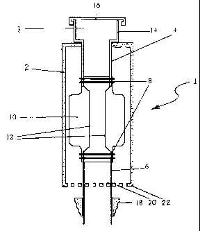
Figure 1 is a cross section through a pressure
relief device,
Figure 2 is a cross section through the housing,
Figure 3 is a.schernatic of the housing and,
Figure 4 is a cross section of two pressure relief
devices connected in series. .
In the drawings, the pressure relief device 1
comprises an external casing 2, a housing 3, a flexible
reservoir 10 and an end cap 16. Figure 1 shows the
assembled pressure relief device. The flexible reservoir
10 covers the central portion of the housing and is
secured to the housing inlet 6 and the housing inlet 4 by
means of an `O'rxng 8. The flexible reservoir 10 is
sealed against the housing inlet 6 and the housing outlet
4 by the 10'ring compressing a layer of sealant (not
shown). This allows the flexible reservoir 10 to operate
without any leakage.

CA 02459523 2004-03-03
WO 03/021049 PCT/IB02/03577
4
The inlet 6 and the outlet 4 of the housing 3 are
linked together by means of separator plates 12 leaving
between them open spaces in contact with the flexible
resevoi.r 10 _
The external casing 2 fits partly over the housing 3
and over the flexible reservoir 10. The external casing
has a plurality of means for ventilation 20, shown for
example here in the base surface 22,_which allows the
flexible reservoir 10 to be in permanent contact with the
atmospheric air (pressure) whilst preventing the flexible
reservoir 10 from being damaged by any external event.
The pressure relief device 1 is attached to the
drainage systern by means of a graduated connector 18. The
graduated connector allows the connection of at least two
different size pipes together in a secure manner, and may
be made of an elastomeric material.
za Figure 2, the housing 3 can be seen to comprise
four distinct sections. The upper section 14 leads to the
housing outlet 4 and the housing inlet 6 via the
separator sections or plates 12. The separator plates 12
allow airflow to continue through the pressure relief
device 1 when the flexible reservoir 10 is fully
collapsed.
Figure 3 is a schematic of the housing 3 without the
upper section 14. It caz2 be seen that the separator
plates 12 do not extend fully round the-circumference of
the housing 3. The gaps between the separator plates 12
allow air from the drainage system to enter the flexible
reservoir 10 and inflate it in case of positive pressure
within the system, thus absorbing the energy of the
transient pressure wave.

CA 02459523 2004-03-03
WO 03/021049 PCT/IB02/03577
Figure 4 shows two pressure relief devices 1
connected in series- The devices are connected together
by means of a graduated connector 18 connecting the
housing inlet 6 of the upper pressure relief device 5
5 into the upper section 14 of the lower pressure relief
device 7.
The connection between two pressure relief devices,
or a pressure relief device and the drainage system, or a
pressure relief device and a.n air admittance valve is
l0 intended to be a push fit connection.
The ground drainage system is designed to be in
accordance with BS 5572: 1978 (Code of Practice for
Sanitary Pipe Work)-
With the present invention, a simple and effective
pressure relief device, that can be retrofitted to
existing drainage systems, is provided.
While only a specific embodiment of the present
invention have been described and shown, it is apparent
that various alterations and modifications can be made
therei.n_ It is therefore the intention in the appended
claims to cover all such modifications and alterations as
may fall within the scope of the claims. -

Representative Drawing
A single figure which represents the drawing illustrating the invention.
Administrative Status

2024-08-01:As part of the Next Generation Patents (NGP) transition, the Canadian Patents Database (CPD) now contains a more detailed Event History, which replicates the Event Log of our new back-office solution.

Please note that "Inactive:" events refers to events no longer in use in our new back-office solution.

For a clearer understanding of the status of the application/patent presented on this page, the site Disclaimer , as well as the definitions for Patent , Event History , Maintenance Fee  and Payment History  should be consulted.

Event History

Description Date
Inactive: Expired (new Act pat) 2022-09-06
Common Representative Appointed 2019-10-30
Change of Address or Method of Correspondence Request Received 2018-12-04
Letter Sent 2016-05-06
Inactive: Single transfer 2016-04-26
Maintenance Request Received 2015-08-25
Maintenance Request Received 2014-08-21
Maintenance Request Received 2013-08-20
Inactive: Correspondence - MF 2010-08-10
Grant by Issuance 2009-12-01
Inactive: Cover page published 2009-11-30
Pre-grant 2009-09-09
Inactive: Final fee received 2009-09-09
Notice of Allowance is Issued 2009-05-27
Letter Sent 2009-05-27
Inactive: Approved for allowance (AFA) 2009-05-25
Amendment Received - Voluntary Amendment 2006-11-14
Letter Sent 2006-10-27
Request for Examination Requirements Determined Compliant 2006-10-11
All Requirements for Examination Determined Compliant 2006-10-11
Request for Examination Received 2006-10-11
Inactive: IPC from MCD 2006-03-12
Letter Sent 2005-03-09
Inactive: Single transfer 2005-02-03
Inactive: Courtesy letter - Evidence 2004-05-04
Inactive: Cover page published 2004-04-30
Inactive: Notice - National entry - No RFE 2004-04-28
Application Received - PCT 2004-04-02
National Entry Requirements Determined Compliant 2004-03-03
Application Published (Open to Public Inspection) 2003-03-13

Abandonment History

There is no abandonment history.

Maintenance Fee

The last payment was received on 2009-08-13

Note : If the full payment has not been received on or before the date indicated, a further fee may be required which may be one of the following

  • the reinstatement fee;
  • the late payment fee; or
  • additional fee to reverse deemed expiry.

Patent fees are adjusted on the 1st of January every year. The amounts above are the current amounts if received by December 31 of the current year.
Please refer to the CIPO Patent Fees web page to see all current fee amounts.

Owners on Record

Note: Records showing the ownership history in alphabetical order.

Current Owners on Record
WATERTITE PRODUCTS, INC.
Past Owners on Record
DAVID CAMPBELL
JOHN SWAFFIELD
Past Owners that do not appear in the "Owners on Record" listing will appear in other documentation within the application.
Documents

To view selected files, please enter reCAPTCHA code :


To view images, click a link in the Document Description column. To download the documents, select one or more checkboxes in the first column and then click the "Download Selected in PDF format (Zip Archive)" or the "Download Selected as Single PDF" button.

List of published and non-published patent-specific documents on the CPD .

If you have any difficulty accessing content, you can call the Client Service Centre at 1-866-997-1936 or send them an e-mail at CIPO Client Service Centre.


Document
Description 
Date
(yyyy-mm-dd) 
Number of pages   Size of Image (KB) 
Description 2004-03-02 5 183
Representative drawing 2004-03-02 1 8
Drawings 2004-03-02 3 37
Claims 2004-03-02 2 67
Abstract 2004-03-02 2 60
Description 2006-11-13 6 198
Claims 2006-11-13 3 96
Representative drawing 2009-11-03 1 6
Notice of National Entry 2004-04-27 1 192
Reminder of maintenance fee due 2004-05-04 1 109
Request for evidence or missing transfer 2005-03-06 1 101
Courtesy - Certificate of registration (related document(s)) 2005-03-08 1 105
Acknowledgement of Request for Examination 2006-10-26 1 176
Commissioner's Notice - Application Found Allowable 2009-05-26 1 162
Courtesy - Certificate of registration (related document(s)) 2016-05-05 1 125
PCT 2004-03-02 13 415
Correspondence 2004-04-27 1 25
Fees 2004-08-19 1 27
Fees 2005-08-09 1 26
Fees 2006-08-07 1 33
Fees 2007-07-09 1 42
Fees 2008-08-10 1 42
Correspondence 2009-09-08 2 55
Fees 2009-08-12 1 53
Correspondence 2010-08-09 1 44
Fees 2010-07-29 1 33
Fees 2011-08-18 1 33
Fees 2012-07-19 1 36
Fees 2013-08-19 1 38
Fees 2014-08-20 1 39
Maintenance fee payment 2015-08-24 1 37