Language selection

Search

Patent 2460461 Summary

Third-party information liability

Some of the information on this Web page has been provided by external sources. The Government of Canada is not responsible for the accuracy, reliability or currency of the information supplied by external sources. Users wishing to rely upon this information should consult directly with the source of the information. Content provided by external sources is not subject to official languages, privacy and accessibility requirements.

Claims and Abstract availability

Any discrepancies in the text and image of the Claims and Abstract are due to differing posting times. Text of the Claims and Abstract are posted:

  • At the time the application is open to public inspection;
  • At the time of issue of the patent (grant).
(12) Patent Application: (11) CA 2460461
(54) English Title: ASSEMBLY FOR LAMP CONSTRUCTION AND ASSOCIATED LAMP AND METHOD FOR CONNECTING THE ASSEMBLY
(54) French Title: MONTAGE DE LAMPE, ET LAMPE ET METHODE DE RACCORDEMENT ASSOCIEES
Status: Deemed Abandoned and Beyond the Period of Reinstatement - Pending Response to Notice of Disregarded Communication
Bibliographic Data
(51) International Patent Classification (IPC):
  • H01J 61/36 (2006.01)
  • H01J 05/32 (2006.01)
  • H01J 09/28 (2006.01)
  • H01J 09/32 (2006.01)
  • H01J 61/04 (2006.01)
  • H01J 61/82 (2006.01)
  • H01K 01/38 (2006.01)
(72) Inventors :
  • MITTLER, BODO (Germany)
(73) Owners :
  • PATENT-TREUHAND-GESELLSCHAFT FUER ELEKTRISCHE GLUEHLAMPEN MBH
(71) Applicants :
  • PATENT-TREUHAND-GESELLSCHAFT FUER ELEKTRISCHE GLUEHLAMPEN MBH (Germany)
(74) Agent: SMART & BIGGAR LP
(74) Associate agent:
(45) Issued:
(22) Filed Date: 2004-03-10
(41) Open to Public Inspection: 2004-09-14
Availability of licence: N/A
Dedicated to the Public: N/A
(25) Language of filing: English

Patent Cooperation Treaty (PCT): No

(30) Application Priority Data:
Application No. Country/Territory Date
103 11 305.3 (Germany) 2003-03-14

Abstracts

English Abstract


An assembly for lamp construction, comprising a solid W
component (10) and at least one film (9) having two
contact faces, comprising a metallic molybdenum base
body and a coating, which is applied at least in part
to said base body and which comprises ruthenium or
rhenium alone or as an alloy in the region of the first
contact face, which produces the contact with the W
component, whereas the second contact face is not
coated and is intended to be in contact with glass.


Claims

Note: Claims are shown in the official language in which they were submitted.

-7-
Claims:
What is claimed is:
1. An assembly for lamp construction, comprising a
solid component, which is largely made of tungsten and
is referred to below as a W component, and at least one
molybdenum film which has two contact faces, of which a
first contact face is in contact with the W component,
wherein the film is coated on one side in the region of
the first contact face, this coating comprising
ruthenium and/or rhenium, whereas the second contact
face is not coated and is intended to be in contact
with glass.
2. The assembly as claimed in claim 1, wherein the
coating is made of pure ruthenium or rhenium or a
rhenium or ruthenium compound or alloy, in particular a
eutectic molybdenum/ruthenium alloy.
3. The assembly as claimed in claim 1, wherein the
thickness of the coating is between 0.02 and 1.0 µm, in
particular 0.02 to 0.09 µm.
4. The assembly as claimed in claim 1, wherein the W
component is an electrode rod or a disk.
5. A lamp having the assembly as claimed in claim 1.
6. The lamp as claimed in claim 5, further comprising
a hard-glass or silica-glass lamp vessel, which is
provided at least at one end with a sealing-off
extension and contains a luminous element and,
possibly, a filling, the assembly being part of the
seal.
7. The lamp as claimed in claim 5, wherein the lamp
vessel has, in the form of an extension, a neck seal,
the W component being an electrode rod.

-8-
8. The lamp as claimed in claim 7, wherein two
electrodes, which are each held by means of an
electrode rod, are positioned diametrically opposite
one another in the lamp vessel, a supporting roll,
which is fused to the bulb wall in the region of the
bulb neck, surrounding each rod in the front part of
the bulb neck, and at least one film, which has a fold
bearing against the supporting roll for the purpose of
fixing said supporting roll, being inserted between the
supporting roll and the electrode rod.
9. The lamp as claimed in claim 8, wherein the free
end of the film is welded to the electrode rod behind
the fold.
10. A method for producing an assembly between a
molybdenum film and a solid W component, wherein the
film is provided on one side with a rhenium- or
ruthenium-containing coating in the region of the
contact face to the W component, and then the film is
welded to the W component in the region of the contact
face to an assembly having an electrically conducting
connection.
11. The method as claimed in claim 10, wherein the W
component is a rod or a disk.
12. The method as claimed in claim 11, wherein, for
the purpose of fixing a glass component to a rod, the
method is used such that the film is moved along a
central axial hole in the glass component, and then the
end of the film which still protrudes on the glass
component is gathered to form a fold, which bears
against the glass component, and then the remaining
free end of the film is welded to the rod.

-9-
13. The method as claimed in claim 12, wherein either
the film is introduced into the glass component or the
glass component is pushed onto the film.

Description

Note: Descriptions are shown in the official language in which they were submitted.


CA 02460461 2004-03-10
2003P03759US-WER
Patent-Treuhand-Gesellschaft
fur elektrische Gliihlampen mbH., Munich
Title: Assembly for lamp oonstruction and associated
lamp and method for connecting the assembly
Technical field
The invention relates to an assembly for lamp
construction and an associated lamp, and a method for
connecting the assembly. The assembly for lamp
construction is comprising a solid component, which is
Flargely made of tungsten and is referred to below as a
w component, and at least one molybdenum film which has
two contact faces, of which a first contact face is in
contact with the W component. The invention relates in
particular to high-pressure discharge lamps having a
metal halide filling for photo-optical purposes, but
also to other types of incandescent lamps and discharge
lamps, for example xenon lamps.
Background Art
An assembly for lamp construction and an associated
lamp and a method for connecting the assembly has
already been disclosed in DE-A 196 18 967. Here, the
glass component is referred to as a securing component.
This component, which is often also referred to as a
supporting roll, is fixed by means of a molybdenum
stopper, evidently a wire. The stopper is clearly
simply pushed onto the electrode rod, but cannot be
fixed, since molybdenum cannot be welded to solid
tungsten.
A similar technique is disclosed in US 6 262 535. Here,
the supporting roll is fixed owing to its conical
shape, and owing to the fact that the neck of the

CA 02460461 2004-03-10
discharge vessel bears closely against the supporting
roll.
Disclosure of the Invention
It is an object of the present invention to provide an
assembly for lamp construction which is comprising a
solid component, which is largely made of tungsten and
is referred to below as a W component, and at least one
molybdenum film which has two contact faces, of which a
(first contact face is in contact with the W component,
which can be fixed in a simple and reliable manner. A
further object is to specify a method for the
production of such an assembly.
These objects are achieved by the following features:
the film is coated on one side in the region of the
first contact face, this coating comprising ruthenium
and/or rhenium, whereas the second contact face is not
coated and is intended to be in contact with glass.
The object of the method for producing an assembly
between a molybdenum film and a solid W component is
achieved by the following features: the film is
provided on one side with a rhenium- or
ruthenium-containing coating in the region of the
contact face to the W component, and then the film is
welded to the W component in the region of the contact
face to an assembly having an electrically conducting
connection.
Particularly advantageous refinements are described in
the dependent claims.
The present invention develops further the possible
solutions described in the teaching of US 6 624 576 in
that a molybdenum film (typically 100 Elm thick) is

CA 02460461 2004-03-10
- 3 -
coated on one side with pure rhenium or ruthenium or a
mixture thereof or a compound comprising ruthenium or
rhenium. Particularly suitable coating materials are
pure ruthenium and a molybdenum/ruthenium alloy having
a eutectic composition.
The thicknesses of the rhenium- or ruthenium-containing
layer are preferably in the range from 0.02 to 1.0 Vim.
In a particularly preferred embodiment, the thickness
is from 0.02 to 0.09 Vim.
The coating may be carried out using known coating
methods, preferably by sputtering.
The molybdenum films coated with rhenium or ruthenium
or alloys thereof can be welded very effectively; in
contrast to uncoated molybdenum films or molybdenum
wires. The coated side of the molybdenum film can thus
be welded directly to a solid W component, in
particular a rod or a disk. The particular advantage is
that different thicknesses and shapes of the W
component are insignificant, since they can be provided
with the same coated film, and that additional welding
aids can be dispensed with.
In a preferred embodiment, one or more molybdenum films
are welded directly to the solid W component, that is
without the otherwise conventional welding aids such as
tantalum or platinum. The component is made either
completely or largely from tungsten; in this case it is
slightly' doped in the conventional manner, for example
with aluminum or potassium.
In a further particularly preferred embodiment, the
molybdenum films are used to fix a glass component by
them being used on the solid W component as an
interlayer between the latter and the glass component.
The glass component is fixed by means of a fold, which
is produced by pushing the part of the film which

CA 02460461 2004-03-10
-
protrudes on the glass component together. The film is
then welded to the W component.
The electric lamps according to the invention have a
silica-glass or hard-glass lamp vessel, which is
provided with - usually two - necks, in each of which
there is a solid W component as part of the bushing.
There is at least one molybdenum film on the W
component with its coated side facing the W component
and being welded to said W component.
A method for fixing a glass component is based on the
production of a fold in the film, which can then serve
the purpose of fixing the glass component. The
molybdenum film, which is coated on one side, is then
finally fixed to the W component by means of welding.
Brief description of the drawings
The invention is explained in more detail below with
reference to two or more exemplary embodiments. In the
drawing:
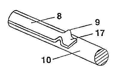
figure 1 shows a partial section through a metal
halide lamp (figure la); and a
perspective detail thereof (figure 1b);
AN F
figure 2 shows a section through a further
exemplary embodiment (figure 2a) and a
side view thereof (figure 2b).
Best Mode for Carrying Out the Invention
Figure la shows a section through a mercury
high-pressure discharge lamp 1 having an output of
2.5 kW. It has a silica-glass bulb 2 having a wall
thickness of 4 mm. It is elliptical, in the form of a
barrel, or the like, and surrounds a discharge volume
3. Connected to this, on both sides, diametrically

CA 02460461 2004-03-10
- 5 -
apposite one another, are two bulb necks 4 (only one is
shown), which each contain a seal. These have, in
relation to the discharge volume 3, a front part 4a,
which contains a cylindrical, silica-glass supporting
roll 5, and a rear cylindrical part 4b, which forms the
sealing-off seal. The front part 4a has a recess 6 of
5 mm in length. Connected to this is a supporting roll
5 having a hole 7, which is cylindrical, or else
conical. Its inner diameter is 7 mm, its outer diameter
is 15 mm. The wall thickness of the bulb is
approximately 4 mm in this region. The axial length of
the supporting roll is 22 mm.
An electrode rod 10, which is made of solid tungsten,
has a diameter of 6 mm and reaches into the discharge
volume, where it bears an electrode head 11 as the
anode, is guided axially in the central hole 7 in the
supporting roll. The rod 10 is extended to the rear
beyond the supporting roll 5 and ends at a plate 12
which is adjoined by a cylindrical, quartz block 13.
Behind this is a second plate 14, which holds an outer
power supply line in the form of a molybdenum rod 15 in
the center. Four molybdenum films 16 are guided, in a
manner known per se, along the outer face of the quartz
block and sealed in on the wall of the bulb neck. They
are spot-welded to the tungsten plates 12 and 14.
The supporting roll 5 is fixed by means of four
molybdenum films 8, which are distributed along the
circumference of the W rod 10 (only two of which can be
seen in figure 1). However, in principle, just two
mutually opposing molybdenum films suffice for fixing
purposes. The films 8 each have a fold 9, which fixes
the supporting roll, see the detail drawing in figure
lb. The film 8 is welded, on the one hand, to the rod
10 at the end of said rod 10 which is remote from the
discharge. Once the fold 9 has formed, the film 8 is
also spot-welded at its end 17 which is initially still

CA 02460461 2004-03-10
- 6 -
free. A particular advantage of this film is that it
fixes the glass component or the supporting roll.
In a simple variant of the invention, the solid W
component is a disk 20, see figures 2a and 2b, to which
the Ru-coated side 22 of the molybdenum films 21 is
fixed. In this case too, preferably two or four films
(figure 2b) can be distributed over the circumference
of the disk 20. A welding aid, for example a tantalum
film, is avoided in this manner: The second side 23 of
the film 21 remains uncoated, so that the glass adheres
here, resulting in a sealed connection between the
quartz block and the bulb.

Representative Drawing
A single figure which represents the drawing illustrating the invention.
Administrative Status

2024-08-01:As part of the Next Generation Patents (NGP) transition, the Canadian Patents Database (CPD) now contains a more detailed Event History, which replicates the Event Log of our new back-office solution.

Please note that "Inactive:" events refers to events no longer in use in our new back-office solution.

For a clearer understanding of the status of the application/patent presented on this page, the site Disclaimer , as well as the definitions for Patent , Event History , Maintenance Fee  and Payment History  should be consulted.

Event History

Description Date
Inactive: IPC deactivated 2021-11-13
Inactive: IPC expired 2012-01-01
Application Not Reinstated by Deadline 2009-03-10
Time Limit for Reversal Expired 2009-03-10
Deemed Abandoned - Failure to Respond to Maintenance Fee Notice 2008-03-10
Inactive: IPC from MCD 2006-03-12
Application Published (Open to Public Inspection) 2004-09-14
Inactive: Cover page published 2004-09-13
Inactive: IPC assigned 2004-06-16
Inactive: First IPC assigned 2004-06-16
Inactive: Filing certificate - No RFE (English) 2004-04-14
Letter Sent 2004-04-14
Application Received - Regular National 2004-04-14

Abandonment History

Abandonment Date Reason Reinstatement Date
2008-03-10

Maintenance Fee

The last payment was received on 2007-02-14

Note : If the full payment has not been received on or before the date indicated, a further fee may be required which may be one of the following

  • the reinstatement fee;
  • the late payment fee; or
  • additional fee to reverse deemed expiry.

Patent fees are adjusted on the 1st of January every year. The amounts above are the current amounts if received by December 31 of the current year.
Please refer to the CIPO Patent Fees web page to see all current fee amounts.

Fee History

Fee Type Anniversary Year Due Date Paid Date
Application fee - standard 2004-03-10
Registration of a document 2004-03-10
MF (application, 2nd anniv.) - standard 02 2006-03-10 2006-02-20
MF (application, 3rd anniv.) - standard 03 2007-03-12 2007-02-14
Owners on Record

Note: Records showing the ownership history in alphabetical order.

Current Owners on Record
PATENT-TREUHAND-GESELLSCHAFT FUER ELEKTRISCHE GLUEHLAMPEN MBH
Past Owners on Record
BODO MITTLER
Past Owners that do not appear in the "Owners on Record" listing will appear in other documentation within the application.
Documents

To view selected files, please enter reCAPTCHA code :


To view images, click a link in the Document Description column. To download the documents, select one or more checkboxes in the first column and then click the "Download Selected in PDF format (Zip Archive)" or the "Download Selected as Single PDF" button.

List of published and non-published patent-specific documents on the CPD .

If you have any difficulty accessing content, you can call the Client Service Centre at 1-866-997-1936 or send them an e-mail at CIPO Client Service Centre.


Document
Description 
Date
(yyyy-mm-dd) 
Number of pages   Size of Image (KB) 
Claims 2004-03-09 3 93
Abstract 2004-03-09 1 19
Description 2004-03-09 6 255
Drawings 2004-03-09 2 28
Representative drawing 2004-07-21 1 6
Courtesy - Certificate of registration (related document(s)) 2004-04-13 1 105
Filing Certificate (English) 2004-04-13 1 158
Reminder of maintenance fee due 2005-11-13 1 109
Courtesy - Abandonment Letter (Maintenance Fee) 2008-05-04 1 178
Reminder - Request for Examination 2008-11-11 1 128