Note: Descriptions are shown in the official language in which they were submitted.
CA 02461004 2004-03-18
,
~x
TRANSLATION (HM-568PCT-original):
WO 03/027,346 A1
PCT/EP02/09,573
METHOD AND DEVICE FOR COATING THE SURFACE
OF ELONGATED METAL PRODUCTS
The invention concerns a method and device for coating the
surface of elongated metal products, especially strip or wire,
in which the product to be coated passes continuously through a
hot dip bath filled with a molten coating material.
EP 0 630 421 B1 describes a method of this general type, in
which steel strip is furnished with a metal coating. To this
end, the steel strip is fed vertically from below into a coating
system, which has a coating tank (hot dip bath) filled with
molten coating material. As the metal strip is passed
vertically through the coating tank from above, coating material
is deposited on the surface of the metal strip. Similar methods
are also described in EP 0 630 420 B1 and EP 0 673 444 B1. In
the method described in EP 0 630 420, several dip tanks are
arranged one above the other in the vertical direction, and a
multilayer coating is deposited on the product to be coated.
1
CA 02461004 2004-03-18
a~
In hot dip coating methods of this type, the strip is
coated with zinc, aluminum, Zn-A1, or Al-Si alloys. In a first
type of procedure, the strip runs from an annealing furnace with
the exclusion of air into a large tank containing the molten
material, in which it is deflected in the vertical direction and
stabilized by different nondriven rollers. This applies to all
of the specified coating metals or alloys used in hot dip
coating. A disadvantage with the use of a large hot dip tank is
that the rollers and the bearings of the rollers are located
within the molten material, thus all parts are exposed to
chemical attack by the molten material. Accordingly, the
service life of the parts that are used within the molten
material is relatively short. In addition, a large volume of
molten material with a correspondingly large dip bath is
necessary to accommodate the entire roller system. 200 to 300 t
of molten zinc are customary in hot dip galvanizing. Due to
this large volume, rapid regulation of the temperature of the
melt and regulation of the alloy composition is not possible.
Therefore, fluctuations in temperature and alloy composition
must be accepted, which can lead to loss of quality.
Another disadvantage of this method is that the
2
~
CA 02461004 2004-03-18
T f
installation speed cannot be arbitrarily increased to realize an
economical operation, especially when thin strip with a gauge of
less than 0.5 mm is to be coated. The reason for this is that
relative motion can develop between the rollers located in the
bath and the strip. If the tension on the strip is increased in
an effort to avoid this problem, there is the risk of strip
breakage. This results in scrap and prolonged plant shutdown.
The jet stripping system located above the hot dip bath
further limits the maximum possible advance speed of the strip
to be coated by hot dip galvanizing. The coating thickness is
adjusted there by air or nitrogen, and the minimum coating
thickness that can be produced increases with increasing strip
speed. This means that thin coatings cannot be applied at high
strip speeds. However, certain demanding applications require
thin coatings (e.g., less than 25 g/m2 on one side in hot dip
galvanized sheet).
In this regard, it is known that raising the temperature of
the melt in the hot dip bath, for example, in the case of hot
dip galvanizing, from 460°C to above 500°C, reduces the dynamic
viscosity by more than 300. Theoretically, therefore,
temperature elevation improves the flow of the liquid coating
3
CA 02461004 2004-03-18
, .
metal back into the hot dip bath and thus reduces the coating
thickness. However, this approach is associated with the
problem that, when such a large amount of melt is used (200 to
400 t of molten zinc), reproducible regulation of the
temperature of the bath is practically impossible.
Another problem that must be considered in connection with
the method described above is the chemical attack of the melt on
the parts installed in the hot dip bath. This attack
progressively increases at temperatures above 500°C. This means
that the rollers and bearings located in the hot dip bath much
be changed even more frequently. This in turn significantly
reduces the efficiency of the installation and impairs the
economy of the method accordingly.
An arbitrary increase in the temperature of the hot dip
bath is also out of the question for the following reason:
increasing temperatures are accompanied by increasing
accumulation of slag in the bath. This has very adverse effects
on the quality of the coating.
The problem of a very large amount of melt in the hot dip
bath can be avoided by solutions of the types specified in the
documents cited above. It is known from these documents that
4
~
CA 02461004 2004-03-18
hot dip coating can be carried out by preparing the strip in an
annealing furnace, deflecting it vertically, and then passing it
into a hot dip bath from below. The underside of the hot dip
bath has a duct-like opening. The melt is prevented from
flowing out of the bath by a magnetic seal, which is produced by
an inductive traveling field.
The hot dip baths disclosed in the cited documents have a
much smaller volume than the processes that were discussed
earlier. Only about 10 t of melt are needed. An advantage here
is that the melt is alloyed and brought to the desired
temperature in a separate vessel. The melt is conveyed into the
hot dip bath by pumps. Another advantage of this method is that
the alloy composition and the temperature can be regulated much
more efficiently here than in the method discussed previously,
which requires a hot dip bath with much more melt.
Stripping systems installed above the hot dip bath for
adjusting and regulating the desired coating thickness are also
used with a hot dip bath with a relatively small amount of melt.
Here too, the maximum possible strip speed of the installation
is limited by the transferable tensile force of the strip to be
coated.
CA 02461004 2004-03-18
Stable and undisturbed strip flow is a prerequisite for a
good coating result and a homogeneous coating on the product to
be coated over the entire width and length of the strip. The
strip must always be guided parallel through the two stripping
jets located on either side of the strip, and constant distances
from the jets must be maintained. This type of strip
stabilization during the operation is very difficult to
maintain. Even slight deviations in the distance from the jets
or waviness in the strip leads to large variations in the
coating thickness over both the width and length of the strip
and with respect to the ratio of the coating thicknesses on the
two sides of the strip.
Therefore, the coating thicknesses obtained with the jet
stripping process always show a certain amount of variation over
the width and length of the strip, and this diminishes the
quality of the coating process. Since the coating thickness
cannot be allowed to fall below the minimum thickness required
for corrosion resistance, this variation in the coating result
means that more coating material must always be applied than
would otherwise be absolutely necessary. This results in
further impairment of the economy of the coating process.
6
CA 02461004 2004-03-18
Therefore, the objective of the invention is to create a
surface-coating method of the type described above and a
corresponding coating device, with which it is possible to
increase the quality of the coating process and at the same time
improve the economy of the process.
The objective with respect to the method is achieved by
performing the following steps:
(a) measuring the thickness of the layer of coating
material applied to the product after it has passed through the
hot dip bath;
(b) comparing the measured coating thickness with a preset
value of the coating thickness and determining the difference
between the two values;
(c) depending on the determined difference: influencing or
modifying at least one parameter of the coating process to bring
the measured value closer to the preset value.
The invention makes use of the recognition that, in the hot
dip coating process, the strip emerging from the hot dip bath
has already been automatically furnished with a layer of coating
material of a certain thickness -- even without additional
measures, such as the jet stripping process -- and that under
7
CA 02461004 2004-03-18
certain circumstances or combinations of process parameters, a
qualitatively high-grade coating can be applied to the product
to be coated.
Advantageously, this makes it possible to operate a hot dip
coating process of the specified type at very high conveyance
speeds of the product to be coated. Speeds of 300 m/min are
possible for a strip with a gauge of less than 0.5 mm. This
results in a high output of the coating installation and
correspondingly high economic efficiency.
It is also advantageous in the method of the invention that
a uniform coating thickness is formed over the entire width of
the strip, completely independently of the coating parameters,
since the coating parameters all act homogeneously over the
width of the strip. The strip flow and the strip flatness also
have no effect on the coating thickness. The production of a
uniform coating thickness over the entire width and length of
the strip is guaranteed by rapid regulation of the process
parameters.
The product to be coated preferably passes vertically
upward through the hot dip bath.
The control or automatic regulation of various parameters
8
CA 02461004 2004-03-18
, r
of the coating process was found to be especially advantageous
for efficient utilization of the proposed method.
First of all, it can be provided that the controlled or
automatically regulated parameter of the coating process is the
conveyance speed in the advance direction of the product to be
coated. In this connection, it can be provided that the
conveyance speed be increased if the measured thickness becomes
too great.
Alternatively or additionally, the melt bath temperature in
the hot dip bath may be used as a parameter; in this case, it
may generally be provided that the melt bath temperature be
increased if the measured thickness becomes too great (the
viscosity of the coating material decreases as a result, and a
thinner coating film is obtained).
Another suitable parameter is the dipping length or the
height of the melt bath, over which the product to be coated is
in contact with the molten coating material in the hot dip bath.
If the measured thickness becomes too great, the dipping length
or the height of the melt bath can be decreased to obtain better
coating results.
Another alternative or additional parameter of the coating
9
CA 02461004 2004-03-18
process is the temperature of the product, preferably before its
entrance into the hot dip bath. In this case, the temperature
of the product is generally increased if the measured thickness
becomes too great.
Furthermore, the immersion time of the product to be coated
in the hot dip bath is a preferred parameter of the coating
process; in this case, the immersion time can be reduced if the
measured thickness becomes too great.
Finally, another parameter that may be used (once again,
alternatively or additionally) is the composition of the melt in
the hot dip bath.
In accordance with the invention, the device for coating
the surface of the product to be coated as it passes
continuously, preferably vertically, through the hot dip bath is
characterized by the fact that a device for measuring the
thickness of the layer of coating material applied to the
product is installed after the hot dip bath (in the direction of
conveyance), which supplies the measured thickness value to a
control or automatic regulation device, which compares the
measured value with a preset value of the coating thickness and,
depending on the determined difference between the two values,
CA 02461004 2004-03-18
controls means by which at least one parameter of the coating
process can be influenced or modified to bring the measured
value closer to the preset value.
It is advantageous for the mechanism to influence the
conveyance speed of the product to be coated in the direction of
advance of the product. Alternatively or additionally, the
mechanism may influence the melt bath temperature in the hot dip
bath. In addition, it is possible to influence the dipping
length or the melt bath height, over which the product to be
coated is in contact with the molten coating material in the hot
dip bath. It is also possible to influence the temperature of
the product, preferably before it enters the hot dip bath.
To allow efficient influencing of the composition of the
coating metal in the hot dip bath, the hot dip bath can be
connected with a reservoir for molten coating material. The
invention provides that the volume capacity of the hot dip bath
is considerably smaller than the volume capacity of the
reservoir; in this regard, the capacity of the hot dip bath is
preferably no more than 200, and more preferably no more than
100, of the capacity of the reservoir.
To seal the bottom of the hot dip bath, it is advantageous
11
CA 02461004 2004-03-18
to provide a magnetic seal in the bottom region of the hot dip
bath; alternatively, however, other sealing systems may also be
used.
A cooling system for the coated product can be installed
above the hot dip bath. The device for measuring the thickness
is then preferably installed between the hot dip bath and the
cooling system.
The drawings show an embodiment of the invention.
-- Figure 1 is a schematic representation of the design of
the device for coating the surface of an elongated metal
product.
-- Figure 2 is a schematic representation of the automatic
control concept in accordance with the invention.
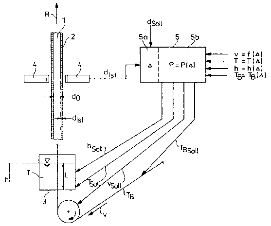
Figure 1 shows a device with which a product 1 to be
coated, shown here as steel strip, is coated with a metal
coating material 2 (for example, zinc).
To obtain uniform coating of both sides of the strip-shaped
product, the strip 1 is fed vertically upward through the hot
dip bath 3, which is filled with molten coating material 2 to a
desired molten bath height "h~~. A magnetic seal 8 is installed
in the region of the bottom of the hot dip bath 3 to prevent
12
CA 02461004 2004-03-18
molten coating material 2 from flowing down and out through the
passage duct 10.
The direction of conveyance of the strip 1 is indicated by
"R". A drive motor 6', which is shown only highly
schematically, drives a roller 11 (or several rollers), by which
the strip 1 is conveyed at conveyance speed "v".
The strip 1 is first brought to the desired temperature in
a furnace 12. It then passes through a duct 13 and enters a
furnace housing 14. In the region of the duct 13 and the
furnace housing 14, an induction heater 6 " " is installed, with
which the strip 1 can be quickly and systematically heated as it
passes through. It then has a strip temperature TB before it
enters the hot dip bath 3.
The hot dip bath 3 contains molten coating material 2 at a
melt bath temperature "T". As the strip 1 passes through the
hot dip bath 3, the molten coating material 2 is deposited on
the surface of the strip 1. After the strip 1 leaves the hot
dip bath 3, the coating material 2 solidifies on the product 1,
so that the desired product, namely, a coated metal strip, is
obtained.
Fresh coating material 2 is supplied from a larger
13
CA 02461004 2004-03-18
' . v
reservoir 7, in which the metallurgical processing of the
coating material 2 has previously been carried out. This
metallurgical processing takes the form of oxide separation and
filtration of solid coating material or strip metal crystals
from the molten coating material. In addition, fresh coating
material produced in melting equipment is supplied to the
reservoir.
To bring the coating material 2 in the hot dip bath 3
quickly to the desired temperature, i.e., to adjust the melt
bath temperature "T" quickly and systematically, the hot dip
bath 3 is surrounded by an induction heater 6 " . The volume of
the hot dip bath 3 is quite small relative to the volume of the
reservoir 7. For example, the hot dip bath 3 may hold only
about 5 t of molten zinc for galvanizing the strip 1, whereas
the capacity of the reservoir 7 is several times greater.
Coating material 2 is pumped from the reservoir 7 into the
hot dip bath by a melt pump 6 " '. The composition of the
coating material in the hot dip bath 3 can be adjusted in this
way.
The peripheral equipment necessary for supplying the hot
dip bath 3 with molten coating material 2 and for removing
14
CA 02461004 2004-03-18
molten coating material 2 from the hot dip bath 3 is not shown
in the drawing of the embodiment. Equipment of this type is
already sufficiently well known from the state of the art. See,
for example, the document EP 0 630 421 B1, which was cited
earlier.
A device 4 for measuring the thickness "da~t"al" of the
coating applied to the product 1 is installed directly above the
hot dip bath 3. A cooling device 9, with which the coated,
still hot strip can be cooled, is installed above this device 4.
Additional details of the coating method in accordance with
the application are shown in Figure 2.
The strip 1 has a thickness "do" before it enters the hot
dip bath 3. A layer of coating material 2, which has a desired
thickness "drat", is applied to the strip 1. Of course, in
conventional coating methods, there is more or less great
variation of the thickness actually applied to the strip 1. The
coating thickness effectively produced on the strip is
designated "dactual~~
The device 4 for measuring the thickness "da~t"al" of the
coating, which is installed as closely as possible above the hot
dip bath 3, measures the actual value of the coating thickness
~
CA 02461004 2004-03-18
"da~tual" and supplies this value to a control or automatic
regulation device 5. This device 5 is also provided with the
desired thickness "dset"
In a first section 5a, the difference calculator, the
difference between the desired and actual thickness is first
calculated by the equation
= dactual dset
and then supplied to a second section 5b, the automatic
regulator. Functional relationships between the parameters "P"
of the coating process and this difference are stored in the
automatic regulator. This means that the functional
relationships specify how a parameter "P" must be changed, when
a difference "0" exists, in order to make the difference as
small as possible or, in the ideal case, equal to zero.
The functional relationships are empirically derived from
experiments for concrete applications. In the present
embodiment, they are determined and stored for
-- the conveyance speed "v" as a function of the
difference,
-- the melt bath temperature "T" as a function of the
difference,
16
CA 02461004 2004-03-18
-- the melt bath height "h" (alternatively, the dipping
length "L") as a function of the difference, and
-- the temperature "TB" of the product before the hot dip
bath as a function of the difference.
The layer of coating material 2 deposited on the strip 1 is
applied very uniformly over the width and length of the strip 1,
since no stripping jet systems which could affect the layer are
necessary. Rather, the desired coating thickness "dset"
reproducibly forms as a reaction to the parameters "P" set in
the coating installation by the control or automatic regulation
device 5, which is shown only highly schematically in Figure 2.
If the actual coating thickness "da~t"al" is greater than the
desired thickness "deer", the control or automatic regulation
device 5 causes the conveyance speed "v" of the strip to be
increased, and/or the melt bath temperature "T" to be increased,
and/or the melt bath height "h" to be reduced, and/or the
temperature "TB" of the strip to be increased. All of these
measures cause a decrease in the coating thickness. If
necessary, the coating thickness can be increased by changing
the parameters in the opposite directions. In this way, the
effective coating thickness "da~t"al" on the metal strip 1 can be
17
CA 02461004 2004-03-18
sensitively adjusted.
An intelligent control or automatic regulation model is
thus used in accordance with the invention. The control or
automatic regulation system is continuously supplied with all
necessary measurement data, which is stored. The functional
relationships between the parameters are stored in the automatic
regulation or control system.
In addition to the regulated quantities that have been
specified, the composition of the hot dip bath and the surface
roughness of the strip are determined, so that in a given case
it is also possible to resort to these parameters for control or
automatic regulation, or so that these parameters can also be
taken into consideration in the control and automatic
regulation.
Rapid control or automatic regulation of the temperature of
the hot dip bath 3 and the product 1 is possible by means of the
inductive heaters 6 " and 6 " " , respectively. In regard to the
composition of the melt in the hot dip bath 3, the goal is
generally not so much rapid automatic regulation as maintenance
of constant alloy components. The fluid coupling of the (small)
hot dip bath 3 with the (large) reservoir 7 is advantageous for
18
CA 02461004 2004-03-18
this purpose. By contrast, very rapid automatic regulation of
the melt temperature must be possible. The inductive heater 6 "
can also be installed for this purpose, for example, at the
inlet of the melt into the hot dip bath 3.
The proposed design allows significant improvement of the
homogeneity of the coating thickness over the width and length
of the strip. There is no dependence on the strip flow or on
constant distances of the strip from the jets of well-known
stripping jet systems, since these are eliminated in the present
invention. Accordingly, the distances between the strip and the
jet, which usually can be controlled only with considerable
difficulty anyway, cannot have any effect. All of the strip
guide rollers can be driven.
Furthermore, since there are no longer any stripping jets,
no medium (air or oxygen) is brought onto the surface of the
strip or onto the still liquid coating material, which otherwise
often has very negative effects on the surface of the strip and
thus on its quality at low coating thicknesses and high
stripping pressures. In this connection, an economic advantage
is gained by virtue of the fact that expensive media (nitrogen)
and power (for fan motors) are no longer needed, which
19
CA 02461004 2004-03-18
simplifies the whole process and makes it more economical. The
installation shutdowns required for changing deflecting rollers
in the melt bath are also eliminated, and the installation can
achieve significantly higher strip advance speeds and thus
higher installation outputs even with the coating of thin
strips.
In continuous hot dip galvanizing, in addition to the
variant of pure hot dip galvanized sheet (the coating is
composed almost entirely of zinc with up to 1 wt.% aluminum),
there is the variant of galvannealed sheet. The coating of this
material consists of a layer of Fe-Zn alloy with up to 13 wt.%
Fe and is formed by diffusion annealing immediately following
the hot dip galvanizing.
In a production plant for galvannealed sheet in accordance
with the state of the art, a (reannealing) furnace is installed
above the stripping jets and provides the strip with the heat
necessary for the diffusion process. Galvannealed sheet is
almost exclusively a product for the automobile industry and is
provided with thin coatings.
The proposed process makes it possible to produce
galvannealed sheet in an especially advantageous way directly
CA 02461004 2004-03-18
from the melt without additional repeating at high strip
temperatures and zinc bath temperatures. To this end, the
cooling device 9 above the hot dip bath 3 is shut off.
While in conventional processes, the stripping jet systems
significantly cool the strip emerging from the melt, this is not
the case with the proposed process with the cooling device 9
shut off. Furthermore, the temperature of the hot dip bath in
previously known processes is significantly lower than may be
the case with the proposal in accordance with the invention,
because in the processes in accordance with the state of the
art, it is necessary to counteract the formation of bottom slag.
With the process of the invention, this is not a problem due to
the very small hot dip bath; in this case, it is hardly possible
for bottom slag to form, so that the quality of the product can
also be improved in this respect.
Therefore, the diffusion process in the production of
galvannealed sheet cannot proceed after galvanizing in the
previously known processes and requires renewed heat input. An
advantage of the process of the invention is that this repeating
is not necessary, because the amount of heat still present in
the strip is sufficient for the diffusion.
21
CA 02461004 2004-03-18
List of Reference Numbers
1 product to be coated
2 metal coating material
3 hot dip bath
4 device for measuring the thickness of the coating
control and automatic regulation
device
5a difference calculator
5b automatic regulator
6 means for influencing or modifying a parameter of the
coating process
6' drive motor
6 " induction heater for the hot dip bath 3
6 " me 1 t pump
'
6 " induction heater for the product 1
"
7 reservoir
8 magnetic seal
9 cooling device
passage duct
11 roller
12 furnace
13 duct
22
CA 02461004 2004-03-18
14 furnace housing
dlst (= da~t"al) thickness of coating applied to the product 1
droll (= dset) preset value of the coating thickness
do thickness of the product 1
difference between dactual and dset
P parameter of the coating process
v conveyance speed
R direction of conveyance
T melt bath temperature
L dipping length
h melt bath height
TB temperature of the product before it enters the hot dip
bath
t immersion time
23