Note: Descriptions are shown in the official language in which they were submitted.
CA 02461112 2004-03-15
TITLE OF THE INVENTION
STRAPPING TOOL WELD MOTOR CONTROL SYSTEM
BACKGROUND OF THE INVENTION
[0001] The present invention is directed to a weld motor control
system. More particularly, the present invention is directed to a weld motor
control
system for a strapping tool or strapping machine that provides a consistent
weld or
joint strength regardless of weld motor voltage fluctuations.
[0002] Strapping tools or machines are well known in the art.
Typically these machines are used for securing straps around loads, One type
of
strapper is used with a plastic or polymeric strap and is a stationary
arrangement in
which the strapper is included as part of an overall manufacturing or
packaging
system.
[0003] A strapping or welding head is provided as part of a strapping
machine and provides a number of functions. First, the strapping head includes
a
gripper having one or more gripper portions that grip the strap during the
course of a
strapping operation. The strapping head also includes a cutter to cut the
strap from a
strap source or supply. Last, the strapping head includes a sealer to seal an
overlying
course of strapping material onto itself. This seal is commonly referred to as
a weld
and is effected by heating overlying courses of the strap by use of a
vibrating element.
(0004] To effect the seal or weld, an anvil is maintained rigidly against
one of the courses of strap and a vibrating element oscillates or vibrates
against the
other course of strap, thus creating friction and heat to effect the weld. The
vibrating
element is driven by a motor that is mounted to the body and operably connect
to the
vibrating element. In a typical weld motor arrangement, the weld cycle is
controlled
by time. That is, the weld cycle is a time dependent cycle, typically timed or
controlled by either an electric timing circuit or a pneumatic timing circuit.
[0005] It has, however, been found that the weld motor voltage can
decrease during the weld cycle as much as 3 percent to 4 percent in addition
to a 10
volt fluctuation in the power feed, commonly experienced. Moreover, this
voltage
decrease has been correlated to lower joint strength because the motor speed
decreases as the voltage decreases. In an effort overcome the lower joint
strength,
longer weld times were used. However, it was found that when longer weld times
CA 02461112 2004-03-15
were used in a cycle in which the voltage did not drop, the strap integrity
could be, in
certain instances, compromised.
[0006] Accordingly, there exists a need for a simplified weld motor
control system for a welding or strapping head for use in a strapping machine.
Desirably, such a control system eliminates the dependence upon time as the
controlling factor for the weld cycle. More desirably, such a control system
serves to
provide a consistent strap weld, regardless of fluctuations in the weld motor
voltage.
Most desirably, such a control system is readily adapted to existing strapping
machine
strapping head systems.
BRIEF SUMMARY OF THE INVENTION
[0007] A control system for a weld motor for a strapping machine
includes a sensor and a sensed element located on a rotating portion of the
motor.
The sensor senses rotation of the motor and generates a signal for control of
the
motor. Such a control system is used for controlling the weld motor of a
strapping
machine of the type having a body, an anvil mounted to and movable relative to
the
body, a sealing member disposed for oscillating movement relative to the anvil
and a
motor operably connected to the sealing member to provide oscillating movement
to
the sealing member.
[0008] Such a control system eliminates the dependence upon time as
the controlling factor for the weld cycle and serves to provide a consistent
strap weld,
regardless of fluctuations in the weld motor voltage. Because of its
simplicity, the
present control system is readily adapted to existing strapping machine
strapping head
systems.
[0009] In a present embodiment, the sensed element is an indicia or
marking present on a shaft of the motor and the sensor is a proximity sensor.
positioned near the marking. A counter receives pulses or signals from the
sensor for
each sensed occurrence of the sensed element. A controller receives a signal
from the
counter to control the motor based upon a predetermined number of sensed
occurrences.
[0010] The generated signal can stop rotation of the motor or
commence rotation of the motor. A present control system includes a power
relay
disposed between the controller and the motor. The controller signal is
received by
CA 02461112 2004-03-15
the power relay to generate a signal to control the motor. A method for
controlling
the motor is also disclosed.
[0011] These and other features and advantages of the present
invention will be apparent from the following detailed description, in
conjunction
with the appended claims.
BRIEF DESCRIPTION OF TIDE SEVERAL VIEWS OF THE DRAWINGS
[0012] The benefits and advantages of the present invention will
become more readily apparent to those of ordinary skill in the relevant art
after
reviewing the following detailed description and accompanying drawings,
wherein:
[0013] FIG. 1 illustrates an exemplary strapping machine weld head;
and
[0014] FIG. 2 is a schematic illustration of a control system for a weld
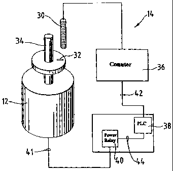
head motor embodying the principles of the present invention.
DETAILED DESCRIPTION OF THE INVENTION
[0015] While the present invention is susceptible of embodiment in
various forms, there is shown in the drawings and will hereinafter be
described a
presently preferred embodiment with the understanding that the present
disclosure is
to be considered an exemplification of the invention and is not intended to
limit the
invention to the specific embodiment illustrated.
[0016] It should be further understood that the title of this section of
this specification, namely, "Detailed Description Of The Invention", relates
to a
requirement of the United States Patent Office, and does not imply, nor should
be
inferred to limit the subject matter disclosed herein.
[001'7] Referring to the figures and in particular FIG. 1, there is shown
a conventional strapping machine weld head 10, exemplary of which is that
disclosed
in Gerhart et al., U.S. Patent No. 6,532,722, which patent is commonly
assigned with
the present application and is incorporated herein by reference. The weld head
10
includes a weld motor 12 that is controlled by a control system 14 embodying
the
principles of the present invention.
[0018] The weld head 10 includes an anvil 16 that is movably mounted
to the strapping head body 18. In a current embodiment, the anvil 16 is
fixedly
mounted to a side plate 20 that moves relative to the body 18. A sealing
member,
CA 02461112 2004-03-15
such as the illustrated vibrating member 22 is disposed in the anvil 16 and
includes a
welding end having a weld pad or weld region (not shown) and a coupling end
24.
[0019] The weld motor 12 is operably connected to the vibrating
member 22 at the coupling end 24 to effect the necessary vibrations or
oscillations of
the member 22. In a current embodiment, the motor 12 is mounted to the body
side
plate 20 and is thus fixedly mounted relative to the anvil 16 and vibrating
member 22.
[0020] To effect oscillation of the vibrating member 22, the motor 12
includes an eccentric drive element 26 (mounted to a non-eccentric shaft 34),
such as
the exemplary eccentric shaft portion extending through a receiving opening
(not
shown) in the vibrating member coupling end 24. A bearing 28 is mounted to the
shaft eccentric 26. The eccentric 26 is configured such that an axis of
rotation is off
center of the shaft 34 axis.
[0021] Referring to FIC3. 2, the motor 12 is controlled by a control
system 14 that, instead of timing the weld cycle, monitors or counts the
number of
revolutions of the motor 12. Thus, even if the voltage of the weld motor 12
varies
(i.e., drops upon actuation and due to supply voltage fluctuations), the total
number of
rotations of the motor 12 (and thus the number of vibrations or strokes of the
vibrating
member 22) remains constant.
[0022] In a current embodiment, the control system 14 includes a
sensor 30, such as a proximity sensor and a target 32 or like sensed element
on the
motor shaft 34. The sensor 30 is operably connected to a counter 36 (such as
the
illustrated counter display) which is in turn operably connected to a
programmable
logic controller (PLC) 38 or like programmable element. The PLC 38 is operably
connected to a power relay 40 that supplies power to or isolates power from
the weld
motor 12 through a power feed 41.
[0023] In a preferred embodiment, the counter 36 is programmable so
that the preset value (e.g., the preset number of rotations) can be changed,
and the
counter 36 provides a control signal (as at 42) to the PLC 38 which signal is
triggered
when the preset revolution value (i.e., count) is reached. The PLC 38 provides
a
control on/off signal (as at 44) to the power relay 40.
[0024] It is anticipated that the counter 36 can be removed (and the
sensor 30 directly providing a control signal to the PLC 38) so long as the
PLC 38 has
a sufficiently fast input to accurately count the proximity sensor pulses.
Those skilled
in the art will recognize the various means in which "counting" the number of
CA 02461112 2004-03-15
rotations can be achieved, which other means are within the scope and spirit
of the
present invention.
[0025] Several tests were conducted to determine the strength of a
weld when the weld was made by: (1) a timed circuit; (2) a timed circuit with
dynamic braking control; (3) motor rotation counts; and (4) motor rotation
counts
with dynamic braking. Each of the tests was conducted with varying weld motor
voltages. In those tests that were conducted without dynamic braking the
motors were
allowed to coast down to a stop. In those tests that were conducted with
dynamic
braking, the motors were stopped using appropriate circuitry. All of the strap
samples
were 3/4 inch wide, 0.060 inch thick polyester strap.
[0026] In the data that follows, the strap weld times were varied from
0.45 seconds to 0.65 seconds (at varying voltages), with results shown in
TABLE 1;
weld time was held constant (at varying voltages) with dynamic braking, with
the
results shown in TABLE 2; strap weld times were measured by the number of
motor
rotations (at varying voltages) without dynamic braking, with the results
shown in
TABLE 3; and by the number of motor rotations (at varying voltages) with
dynamic
braking, with the results shown in TABLE 4.
Weld TimeVoltage Avg. Joint Minimum Total Number
(secs.) (VAC) Strength Joint StrengthAvg. of
ounds Counts Samples
\
0.45 124.6 2313.9 2150 195.80 20
0.45 121.5 2323.5 2133 194.90 30
0.45 108.6 2236.8 2002 173.80 30
0.45 100.5 2004.6 1740 162.73 30
0.55 108.8 2256.9 2049 191.35 20
0.65 108.8 2363.1 2204 212.00 20
TABLE 1 - JOINT STRENGTH WITH VARYING WELD TIMES
AND WELD MOTOR VOLTAGES
Weld Time Voltage Avg. Joint Minimum Total Number
Avg. of
(secs.) (VAC) Strength Joint Counts Samples
Strength
ounds
1.10 121.5 2343.2 2271 223.40 30
1.10 108.3 2340.8 2149 194.57 30
1.10 100.3 2273.2 1866 175.07 15
TABLE 2- JOINT STRENGTH WITH CONSTANT WELD TIMES
AND VARYING WELD MOTOR VOLTAGES, WITH DYNAMIC BRAKING
CA 02461112 2004-03-15
Motor RotationVoltage Avg. Joint Minimum Total Number
Avg. of
Coums (VAC) Strength Joint Counts Samples
Strength
ounds
155 119.3 2354.8 2253 204.27 15
155 106.5 2287.6 2094 192.07 15
155 100.6 2231.3 1973 188.93 15
TABLE 3 - JOINT STRENGTH WITH CONSTANT WELD MOTOR ROTATIONS
AND VARYING WELD MOTOR VOLTAGES, WITHOUT DYNAMIC BRAKING
Motor RotationVoltage Avg. Joint Minimum Total Avg.Number
Counts (VAC) Strength Joint Counts of
ounds Strength Samples
155 119.3 2388.1 2272 162.80 IS
155 108.5 2359.5 2114 162.47 15
155 100.3 2315.3 1840 161.80 15
190 119.3 2367.9 2216 191.87 15
190 108.5 2401.3 2324 197.67 15
190 100.3 2377.8 2264 196.60 15
TABLE 4 - JOINT STRENGTH WITH CONSTANT WELD MOTOR ROTATIONS
AND VARYING WELD MOTOR VOLTAGES, WITH DYNAMIC BRAKING
[0027] Referring to the data of TABLE 1, it can be seen that when
weld time is controlling, the weld strength is clearly affected by the weld
motor
voltage. At a weld time of 0.45 seconds, the average joint strength varied
from
2004.60 pounds at a voltage of 100.5 VAC to 2323.5 pounds at a voltage of
121.5
VAC. The average strength actually dropped (about 9.6 pounds) from 121.5 VAC
to
124.6 VAC. However, the data trend clearly shows a decrease in joint strength
with
decreased voltage. It is also seen that the average and minimum joint strength
(at low
motor voltage operation) can be increased by increasing the weld time. The
data
further shows a correlation between reduced strength and a reduction in the
total
average counts or motor revolutions per weld. However, it was also noted that
at
increased weld times (i.e., at 0.65 seconds), some of the strap samples showed
significant amounts of molten plastic which made it difficult to pull the
strap samples
out of the weld head.
CA 02461112 2004-03-15
[0028] The data of TABLE 2 shows that greater control can be
obtained by the use of dynamic braking. However, again, the average and
minimum
strengtbs continued to decline with decreased voltages.
[0029] The data of TABLE 3 shows that the average and minimum
joints strengths are better controlled when the number of rotations of the
motor
controls the weld cycle. However, again, when there is a higher voltage, the
strength
appears also to increase, however less than as shown in the previous data. It
is
believed that this is due to an increase in coast down time with higher
voltages.
[0030] TABLE 4 shows that when the number of rotations of the
motor controls, along with dynamic braking, the joint strength can be quite
well
controlled and maintained at a level higher than a pre-established threshold
value. As
seen in TABLE 4, when the number of motor rotations is set at 190, even with
variations in voltage between 100.3 VAC and 119.3 VAC (variations of almost 20
percent in voltage), the average joint strength varies less than 1.5 percent
(33.4
pounds). Thus, the data clearly shows that regardless of motor voltage
fluctuations
(within reason, of course), by monitoring and setting the weld cycle based
upon the
number of rotations of the motor and by using dynamic braking (i.e., stopping
the
motor rather than allowing it to coast down), the weld joint strength can be
well
controlled with a high level of confidence and with a high level of assurance
of the
joint integrity.
[0031] All patents referred to herein, are hereby incorporated herein by
reference, whether or not specifically done so within the text of this
disclosure.
[0032] In the present disclosure, the words "a" or "an" are to be taken
to include both the singular and the plural. Conversely, any reference to
plural items
shall, where appropriate, include the singular.
[0033] From the foregoing it will be observed that numerous
modifications and variations can be effectuated without departing from the
true spirit
and scope of the novel concepts of the present invention. It is to be
understood that
no limitation with respect to the specific embodiments illustrated is intended
or should
be inferred. The disclosure is intended to cover by the appended claims all
such
modifications as fall within the scope of the claims.