Note: Descriptions are shown in the official language in which they were submitted.
CA 02461737 2004-03-24
WO 03/029115 PCT/US02/31660
Deicer Mixing Apparatus and Method
Field of the Invention
The present invention relates to an apparatus for coating solid deicers. More
particularly, the invention relates to a method and apparatus for coating
solid deicers
with a solution to depress the freezing point of the deicers, provide
corrosion
resistance, and improve their flowability; and to methods for coating solid
deicers.
Background
Solid deicers, such as rock salt or solar salt (sodium chloride) and
abrasives,
such as sand, are commonly applied to roads and other surfaces during winter
months. These solid deicers and abrasives are often pre-wetted before being
stored
or applied. Pre-wetting typically involves addition of a liquid to the solid
deicer or
abrasive in order to give it increased resistance to freezing, improved
storage
characteristics, enhanced flowability, corrosion resistance, and better
deicing
performance. Liquid brines of sodium chloride, calcium chloride, and magnesium
chloride are often used for this purpose.
In order to optimize the use of the pre-wetting liquid, it is necessary to
coat
the solid deicer in a manner that distributes the liquid as uniformly as
possible on the
solid deicer. Problems can arise if the liquid is not uniformly distributed.
For
example, areas with excessive liquid will leach out from the solid deicer,
while areas
with inadequate liquid tend to clump and flow poorly. Thus, it is necessary to
mix
the deicer and liquid thoroughly. However, excessive mixing can cause the
solid
deicer to be crushed into small particles or "fines", making it undesirable
for many
deicing applications.
Therefore, a need exists for an apparatus and method for applying a pre-
wetting liquid to a solid deicer that effectively coats the solid deicer
without
excessively crushing the solid deicer or forming fines.
Summary of the Invention
The present invention is directed to an apparatus for applying a liquid pre-
wetting composition to a solid deicer, to methods of applying a liquid pre-
wetting
composition to a solid deicer, and to solid deicer materials that have been
coated
using the apparatus or method of the invention.
CA 02461737 2004-03-24
WO 03/029115 PCT/US02/31660
The apparatus used to coat the solid deicer generally includes a screw
conveyor. The conveyor has a housing, at least one screw with a plurality of
flights,
at least one inlet for uncoated deicer, at least one inlet for a liquid pre-
wetting
coating composition, and an outlet for the deicer that has been coated with
the liquid
coating composition. The screw contains protrusions or tabs that extend upward
from the surrounding screw surface. These protrusions or tabs aid in the
mixing of
the solid deicer and the liquid pre-wetting composition, and they help produce
a
well-mixed deicer that resists caking and avoids loss of the pre-wetting
composition
to leaching during storage of the coated solid deicer (which can occur when
the pre-
wetting composition and solid deicer are not properly mixed).
In one implementation of the invention, the protrusions in the screw are
formed from areas of the screw that have been partially cut free from the
screw's
major surface and have been bent upward away from screw's major surface. These
protrusions comprise raised portions on the major surface that have been
partially
severed from the surrounding portions of the screw and been reoriented to
extend
away from the surrounding portions. When the protrusions are formed by cutting
and bending a portion of the major surface, an opening in the screw adjacent
to the
raised portion is left behind. Normally the protrusions are positioned along
the
perimeter of the screw. In this implementation the raised portions are
integrally
formed with the major surface, and are actually formed from the major surface,
of
the screw. In an alternative implementation, the protrusions are formed by
bonding
or securing (such as by bolting or welding) protrusions along parts of the
screw
surface.
The conveyor screw aids in the mixing of the solid deicer and liquid pre-
wetting composition, and optionally contains protrusions that help with the
mixing.
Normally the screw contains at least 5 raised portions or protrusions, more
commonly 10 raised portions or protrusions, and even more commonly at least 15
protrusions, and frequently 20 or more protrusions. The protrusions typically
have
an exposed surface area on one side of at least 10 square inches. The raised
portions
on each flight of the screw may have an exposed surface area on at least one
side
ranging up to 15 percent of the surface area of the flight. Although the
number of
raised portions per flight can be varied, it is desirably from 2 to 8,
commonly from 3
to 6, and most typically 4 to 5.
2
CA 02461737 2004-03-24
WO 03/029115 PCT/US02/31660
The invention is also directed to a method of coating salt to be used as a
deicer. The method includes providing a salt composition, such as sodium
chloride,
magnesium chloride, or a combination thereof; providing a liquid deicer
composition; and providing a screw conveyor. The screw conveyor has a major
surface and a plurality of raised portions extending upward from the major
surface.
The solid deicer composition and pre-wetting composition are added into the
screw
conveyor and the combination is advanced through the conveyor to produce a
coated
solid deicer composition.
Various liquid pre-wetting compositions can be used with the method and
apparatus. The compositions are typically liquid deicers and they can be of
various
formulations. For example, on a water free basis they often contain from 1.0
to 70
percent by weight molasses solids, from 0.1 to 40 percent by weight magnesium
chloride, and from 0 to 30 percent by weight of a corrosion inhibitor. In
certain
implementations the liquid deicer composition comprises less than 45 percent
by
weight molasses solids. In specific embodiments the liquid deicer composition
has
less than 45 percent by weight molasses solids. Suitable molasses includes
cane
molasses, beet molasses, citrus molasses, wood molasses, grain molasses, and
combinations thereof.
If magnesium chloride is present, it may be derived from various sources. In
one implementation the magnesium chloride is derived from liquid bittern,
including
liquid bittern containing 30 percent magnesium chloride. In some
implementations
the bittern contains less than 20 percent magnesium chloride by weight.
Various
corrosion inhibitors can be used. When corrosion inhibitors are used, suitable
corrosion inhibitors include, but are not limited to, phosphate salts, such as
orthophosphates, polyphosphates, pyrophosphates, and organic,phosphonates.
Also,
triethanolamine can be used as a corrosion inhibitor in accordance with the
invention. Sodium gluconate can also be added to provide corrosion protection
in
addition to these other corrosion inhibitors or in place of these corrosion
inhibitors.
The solid deicer used with the invention can include sodium chloride,
calcium chloride, urea, acetate salts, and combinations thereof. Suitable
solid
deicers include sodium chloride and magnesium chloride mixtures. A useful
deicer
composition after coating with liquid pre-wetting agent contains less than 13
percent
by weight magnesium chloride, less than 2.0 percent monosodium phosphate, less
than 5.0 percent by weight molasses solids, and about ~0 to 96 percent by
weight
CA 02461737 2004-03-24
WO 03/029115 PCT/US02/31660
sodium chloride, all on a dry solids basis. Generally, even "solid deicers"
will
contain some water and may contain some liquid, such as liquid coating the
deicer as
a result of rain, condensation, or other sources.
The above summary of the present invention is not intended to describe each
discussed embodiment of the present invention. This is the purpose of the
detailed
description which follows.
Figures
Other aspects and advantages of the invention will become apparent upon
reading the following detailed description and upon reference to the drawings,
in
which:
FIG. 1 is side elevational view of a conveyor screw constructed and arranged
in accordance with an implementation of the invention.
FIG. 2 is an end view of the lower portion of the conveyor screw shown in
FIG. 1.
While the invention is susceptible to various modifications and alternative
forms, specifics thereof have been shown by way of example in the drawings and
will be described in detail. It should be understood, however, that the
intention is
not to limit the invention to the particular embodiments described.
Detailed Description
The present invention is directed to an apparatus for applying a liquid pre-
wetting coating to a solid deicer composition, to methods of applying a liquid
pre-
wetting coating to a deicer composition, and to solid deicer compositions that
have
been coated using the apparatus or method of the invention. The various
components of the apparatus and ingredients for the liquid pre-wetting coating
will
now be described in greater detail, along with methods of applying the pre-
wetting
coating and to characteristics of coated deicer compositions made in
accordance
with the invention.
A. General Screw Convenor Apparatus
The apparatus for applying a liquid pre-wetting coating includes a screw
conveyor used to mix the solid deicer and the liquid pre-wetting composition.
The
screw conveyor typically includes a housing containing at least one rotating
4
CA 02461737 2004-03-24
WO 03/029115 PCT/US02/31660
conveyor screw that advances the deicer from an inlet end to an outlet end.
The
screw conveyor should be large enough to effectively mix significant
quantities of
salt. Thus, any effective length of screw conveyor can be used with the
invention.
In some implementations the screw conveyor contains a single or multi-piece
screw
that is at least 5 feet long, the screw is commonly greater than 10 feet long,
more
commonly at least 15 feet long, and even more commonly greater than 20 feet
long.
Suitable conveyor screws can be, for example about 24 feet long.
The screw conveyor is configured so that the liquid pre-wetting composition
can be easily added to the solid deicer. Various application techniques are
suitable
for applying the liquid, and can include pouring or inj ecting the liquid into
the
conveyor housing at the inlet to the conveyor housing where the solid deicer
enters
the housing. The liquid can enter the housing at one location or multiple
locations,
and normally enters in a continuous stream but alternatively can enter in a
pulsed or
intermittent flow. Also, the liquid can enter as a spray. However, in most
implementations the liquid enters the housing in the first half of the
conveyor
housing, and even more typically in the first quarter of the conveyor housing,
in
order to provide as much opportunity as possible to mix the solid deicer and
liquid
pre-wetting composition.
B. Conveyor Screw
In specific implementations of the invention the conveyor includes a screw
that mixes the solid deicer and liquid pre-wetting composition. The conveyor
screw
permits continuous addition of a liquid deicer to the solid deicer material in
a
manner that provides relatively uniform coating of the solid deicer, while
avoiding
excessive deterioration of the size of the solid deicer particles. In
particular, the
conveyor screw permits thorough mixing of the pre-wetting liquid onto the
solid
deicer, improving the flowability of the solid deicer while avoiding excessive
leaching of the liquid pre-wetting composition from the coated solid deicer.
In
addition, the conveyor screw facilitates this uniform coating of the solid
deicer
without excessive grinding of the solid into undesirable fines.
Screws suitable for use with the present invention can take various forms,
and be of various diameters and lengths. Typically the screw is large enough
to
permit high speed production of coated deicer, and thus the screws usually
have an
outer diameter greater than 12 inches. The diameter can be from 18 to 36
inches in
5
CA 02461737 2004-03-24
WO 03/029115 PCT/US02/31660
some embodiments, more typically from about 20 to 28 inches, and even more
typically about 24 inches. However, it is possible to make the conveyor screws
smaller or larger, depending upon the amount of coated deicer that is desired.
The conveyor screws can be of any length that effectively mixes the solid
deicer and liquid pre-wetting material. The length of the conveyor screws used
with
the present invention is typically at least 10 feet, more typically at least 1
S feet, and
even more typically from 20 to 25 feet. Longer and shorter conveyor screws are
also appropriate under some circumstances. The screws can be one single piece
or
can be multiple pieces assembled together.
Each conveyor screw has multiple flights, with each flight being defined as a
length of screw that has a perimeter extending 360 degrees around the screw.
Generally the screw has greater than 4 flights, frequently more than 8
flights, and
can have greater than 12 flights. In one example implementation the screw is
24
inches in diameter and has fights that are two feet long, yielding a total of
12 flights
in a 24 foot conveyor screw.
In one implementation at least some of the flights have protrusions or tabs
extending from the main screw surface (that portion that forms a helix along
the
screw's length). The protrusions assist in producing a well mixed coated
deicer.
The mixing protrusions or tabs can be aligned so that they form a right angle
(90
degrees) with the adjacent major surface of the screw. The angle is generally
about
90 degrees, but can vary from this angle in various implementations of the
invention.
It is normally not necessary to be exactly 90 degrees, and thus the angle can
be about
90 degrees with some variation from manufacturing or use. In addition, other
implementations of the invention can have the protrusions or tabs form a
smaller
angle with the surrounding screw surface. In certain implementations this
angle is
from 75 to 90 degrees, in other implementations this angle is from 60 to 90
degrees,
and in yet other implementations this angle is 45 degrees or greater. In some
implementations the angle is less than 45 degrees. The protrusions generally
extend
in a direction toward the discharge end of the conveyor. In alternative
embodiments
some or all of the protrusions can also extend toward the inlet of the
conveyor.
As stated above, each screw has multiple mixing protrusions. In most
implementations the mixing protrusions are located near the inlet to the screw
conveyor, or at least in the first half of the screw conveyor. However,
additional
protrusions can be located at various locations, including near the outlet end
of the
6
CA 02461737 2004-03-24
WO 03/029115 PCT/US02/31660
conveyor in some embodiments. The mixing protrusions are normally located
along
the perimeter of the screw, and are desirably spaced in manner that more than
one
protrusion can be positioned on a screw flight.
When two or more protrusions are placed per flight, the protrusions are
positioned so as to be less than or equal to about 1 ~0 degrees apart. When
three or
more protrusions are placed per flight, the protrusions are typically
positioned so as
to be less than or equal to about 120 degrees apart. When four or more
protrusions
are placed per flight, the protrusions are typically positioned so as to be
less than or
equal to about 90 degrees apart, and when five or more protrusions are placed
per
flight the protrusions are typically positioned so as to be less than or equal
to about
72 degrees apart.
As stated above, the general location for most or all of the protrusions is in
the first half of the conveyor screw. These protrusions are usually uniformly
placed
around the conveyor screw, but it is possible to configure the protrusions in
groups
separated by gaps in the screw that do not contain protrusions. Each screw
typically
has one or more protrusions, normally more than 10 protrusions, and frequently
greater than 20 protrusions.
The protrusions should be large enough to facilitate thorough mixing of the
solid deicer and coating liquid, without being so large that the mechanical
forces
excessively crush the deicer and turn it into fines. Various sizes of
protrusions can
be used, and they can be modified in number, size, and position in the various
implementations. For example, on a 24-inch conveyor screw the protrusions can
be
about 3 inches wide (the measurement of the protrusion cut from the screw
along the
cut following the radius of the screw) and about 4 inches long (the
measurement of
the protrusion cut from the screw along the line cut along the circumference
of the
screw). Larger and smaller protrusions can be used, but they should be
selected to
provide adequate mixing without excessive crushing of the solid deicer or
clogging
of the conveyor. For example, a protrusion on a 24 inch diameter conveyor
screw
that is 1 inch wide and 4 inches long will mix the solid deicer and liquid pre-
wetting
composition, but not as well as one that is 3 inches wide. Also, a 4 inch wide
by 6
inch long protrusion on a 24 inch diameter conveyor screw will cause mixing,
but
can result in significantly higher crushing of the solid deicer than that from
a 3 inch
by 4 inch protrusion.
7
CA 02461737 2004-03-24
WO 03/029115 PCT/US02/31660
One way to form each of the protrusions is by making two cuts along the
edge of the screw to form a tab that can be bent up away from the screw
surface. A
first cut runs generally along the radius of the screw while the second cut
runs
generally parallel to the outer edge of the screw to leave an approximately
rectangular tab that is secured by only one edge to the rest of the screw.
After these
two cuts have been made the tab is bent away from the screw surface so that it
is
aligned more with the axis of the screw than with the surface of the screw
from
which it has been partially cut.
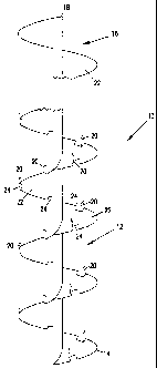
In reference now to the figures, an example conveyor screw constructed in
accordance with the invention is shown in FIG. 1. Conveyor screw 10 is
depicted in
two partial views, with first portion 12 near the input end 14 and a second
portion 16
near output end 18. The conveyor screw 10 contains numerous protrusions 20
that
aid in the mixing of the solid deicer and liquid pre-wetting composition. The
protrusions 20 shown in this example are formed by cutting a portion of the
major
surface 22 of the screw and bending it upward. Gaps 24 are left in the major
surface
22 where the protrusions 20 had previously existed. In the conveyor screw 10
shown in FIG. 1 the protrusions are positioned only on the first~portion 12 of
the
screw near the input end 14, while the opposite end does not have protrusions.
However, as noted earlier, the protrusions can be positioned in various
configurations, and some such protrusions can be positioned near the discharge
end.
In reference now to FIG. 2, a top elevational view of one flight 26 from the
conveyor screw 10 is shown. The depicted flight has five protrusions 20 and
five
gaps 24. In addition, the center axis 28 is shown and the upper edge 30 is
depicted.
C. Solid Deicer
The solid deicer used with the invention can include sodium chloride,
magnesium chloride, calcium chloride, urea, acetate salts, and combinations
thereof.
Suitable solid deicers include sodium chloride and magnesium chloride
mixtures.
The solid deicers can include rock salt, solar salt, other salt sources, and
combinations thereof. The solid deicers are generally prepared in advance of
the
addition of the pre-wetting liquid so that it contains particles of a size
suitable for
application by mechanized equipment (such as salt spreading trucks) onto
roadways
or other surfaces requiring deicing. Thus, it is desirable to preserve the
general size
of the solid deicers during the mixing and coating process. However, some
changes
CA 02461737 2004-03-24
WO 03/029115 PCT/US02/31660
in the size of the solid deicer material normally occurs, but these changes
are
desirably kept to a minimum to avoid formation of large quantities of small
deicer
particles known as fines.
D. Liquid Coating Composition
Various liquid coating compositions are suitable for use with the present
invention as the pre-wetting agent. Often they include or comprise a liquid
deicer.
The liquid deicer compositions typically depress the freezing point of solid
deicers
or abrasives to which they are applied and inhibit corrosion. Thus, the
compositions
aid in prevention of freezing and hardening of solid deicers into large pieces
that are
difficult to apply, and the liquid pre-wetting agent assists in reducing
corrosion of
application equipment and material that comes in contact with the deicer.
In specific implementations the liquid deicer composition can include
molasses solids, magnesium chloride, and a corrosion inhibitor. In one such
implementation the liquid deicer composition includes from 1.0 to 70 percent
molasses solids, from 0.1 to 40 percent magnesium chloride, and from 0 to 30
percent of a corrosion inhibitor.
As used herein, the term "molasses solids" refers to the components of
molasses that are not water, such as various carbohydrates (e.g. sugars) and
proteins.
Typical commercial grade molasses compositions used with the present invention
are approximately 40 to 95 percent molasses solids, more typically
approximately 70
to 85 percent solids. Specific suitable molasses compositions have about 80
percent
solids. Suitable molasses includes cane molasses, beet molasses, citrus
molasses,
wood molasses, grain molasses, and combinations thereof.
The magnesium chloride may be derived, for example, from liquid bittern.
As used herein, liquid bittern is a product derived from sea salt production,
and is
the liquid remaining after removal of sodium chloride from seawater. Liquid
bittern
normally contains water along with a high concentration of magnesium chloride
and
lower concentrations of other salts. In most implementations the liquid
bittern
contains from 20 to 35 percent magnesium chloride. However, in other
implementations liquid bittern contains less than 20 percent magnesium
chloride.
Suitable corrosion inhibitors include phosphate salts, such as
orthophosphates, polyphosphates, pyrophosphates, and organic phosphonates.
Also,
triethanolamine can be use as a corrosion inhibitor in accordance with the
invention.
Sodium gluconate is also acceptable as a corrosion inhibitor. Diammonium
9
CA 02461737 2004-03-24
WO 03/029115 PCT/US02/31660
phosphate and monosodium phosphate are two specific phosphate salts that can
be
used individually or together to provide corrosion inhibition. Calcium
phosphates
are also suitable for use with the invention.
E. Coated Solid Deicer
The resulting coated deicer composition can contain one or more phosphate
salts, molasses solids, magnesium chloride, and sodium chloride. The solid
deicer is
normally present in a significantly greater quantity than the molasses solids
or the
corrosion inhibitor. Typically the amount of solid deicer is greater than
twice the
amount of molasses solids, and even more typically greater than ten times the
amount of the molasses solids. Specific embodiments have at least 0.5 percent
by
weight phosphate salt, at least 0.5 percent by weight molasses solids, at
least 2.0
percent by weight magnesium chloride, and at least 70 percent by weight sodium
chloride.
Example concentrations for the various components are 0.5 to 2.0 percent by
weight of a phosphate salt, 0.5 to 2.0 percent by weight molasses solids, 2 to
6
percent by weight magnesium chloride, and 80 to 97 percent by weight sodium
chloride. These percentages are all given as relative percentages to the other
ingredients that are described. Additional ingredients (such as sand or water)
can
also be added to the composition, but do not change the relative percentages
of these
ingredients.
Suitable specific compositions that can be used as a deicer can include
greater than 0.5 percent by weight magnesium chloride, greater than 1.0
percent by
weight molasses solids, and greater than 80 percent by weight sodium chloride.
For
example, a composition can contain from 0.5 to 13 percent by weight magnesium
chloride, from 1.0 to 3.0 percent by weight molasses solids, and from 85 to 96
percent by weight sodium chloride. Specific compositions contain from 0.5 to
1.5
percent by weight monosodium phosphate, while other compositions contain up to
2.0 percent by weight diammonium phosphate.
Other example composition contains 0.5 to 1.5 percent by weight
monosodium phosphate, 1.5 to 2.5 percent by weight liquid bittern, 1.5 to 2.5
percent by weight cane molasses solids, and 90 to 96.5 percent by weight
sodium
chloride. The liquid bittern in this composition is typically from about 30 to
35
percent magnesium chloride. Thus, the composition contains from about 0.5 to
1.0
CA 02461737 2004-03-24
WO 03/029115 PCT/US02/31660
percent magnesium chloride. Another suitable composition comprises 0.5 to 1.5
percent by weight monosodium phosphate, 0.5 to 1.0 percent by weight
diammonium phosphate, 1.5 to 2.5 percent by weight cane molasses solids, and
90
to 96.5 percent by weight sodium chloride. Yet another suitable composition
comprises 0.5 to 2.0 percent by weight monosodium phosphate, 1.5 to 2.5
percent by
weight cane molasses solids, 1.5 to 2.5 percent chloride salt (such as
magnesium
chloride or calcium chloride), and 90 to 96.5 percent by weight sodium
chloride. A
further acceptable composition contains cane molasses, liquid magnesium
chloride,
and sodium gluconate. Other ingredients may also be included. For example, in
one.
implementation the composition has less than about 10 percent cane molasses,
less
than about 10 percent liquid magnesium chloride, less than about 10 percent
magnesium chloride hexahydrate, less than about 5 percent diammonium
phosphate,
and less than about 5 sodium gluconate, along with solid sodium chloride. One
specific composition containing sodium gluconate has about 2 percent cane
molasses, 2 percent liquid magnesium chloride (30 percent solution), about 7
percent
magnesium chloride hexahydrate, about 1 percent diammonium phosphate, and
about 1 percent sodium gluconate, along with sodium chloride.
F. Method of adding the liquid pre-wetting composition
The conveyor apparatus of the invention is used to mix solid deicer and a
liquid pre-wetting composition, normally a liquid deicer. Solid deicer and the
liquid
pre-wetting composition are normally added continuously to the conveyor and
mixed as they travel from the inlet end to the discharge end.
As described above, many different pre-wetting liquids can be added to the
solid deicer. Also, the pre-wetting compositions can be added in different
quantities
depending upon the nature of the liquid and the desired application. In most
implementations from 5 to 20 gallons of pre-wetting agent are added per ton of
solid
deicer. Even more typically about 8 to 16 gallons are added per ton. In one
implementation a combination of molasses and liquid magnesium chloride is
added
to the solid deicer. For example, approximately 4 gallons of molasses and 4
gallons
of liquid magnesium chloride can be added per ton of salt. Alternatively, 2
gallons
of molasses and 8 gallons of liquid magnesium chloride can be added to the
solid
deicer.
11
CA 02461737 2004-03-24
WO 03/029115 PCT/US02/31660
The solid deicer and the liquid pre-wetting composition should be mixed
sufficiently that excess liquid does not leach from piles of stored deicer.
One way to
determine if the materials are properly mixed is to process approximately 100
tons
of solid deicer and form it into a pile. If liquid pre-wetting agent leaches
from the
pile and accumulates within 24 hours the mixture is generally not adequately
mixed
or contains too much liquid pre-wetting agent.
Also, the composition should not contain excessive fines, which include
solid deicers that pass through a 30 mesh (a mesh having 30 by 30 holes per
square
inch). Fines can be problematic because they can cause caking or
solidification of
the deicer during storage or application. In general the amount of fines, by
weight,
of the solid deicer after addition of the liquid pre-wetting composition
should be less
than 15 percent, more desirably less than 12 percent, and even more desirably
below
9 percent. The amount of fines preferably does not increase significantly
during
addition of the liquid pre-wetting composition and mixing. Generally it is
desirable
that the fines not go up more than 30 percent from their premixing level, and
more
desirably does not go up more than 20 percent, and even more desirably does
not go
up more than 10 percent.
While the present invention has been described with reference to several
particular implementations, those skilled in the art will recognize that many
changes
may be made hereto without departing from the spirit and scope of the present
invention.
12