Language selection

Search

Patent 2461875 Summary

Third-party information liability

Some of the information on this Web page has been provided by external sources. The Government of Canada is not responsible for the accuracy, reliability or currency of the information supplied by external sources. Users wishing to rely upon this information should consult directly with the source of the information. Content provided by external sources is not subject to official languages, privacy and accessibility requirements.

Claims and Abstract availability

Any discrepancies in the text and image of the Claims and Abstract are due to differing posting times. Text of the Claims and Abstract are posted:

  • At the time the application is open to public inspection;
  • At the time of issue of the patent (grant).
(12) Patent Application: (11) CA 2461875
(54) English Title: HEATER FOR OUTDOORS
(54) French Title: CHAUFFERETTE POUR L'EXTERIEUR
Status: Deemed Abandoned and Beyond the Period of Reinstatement - Pending Response to Notice of Disregarded Communication
Bibliographic Data
(51) International Patent Classification (IPC):
  • A47B 37/04 (2006.01)
  • A47B 97/00 (2006.01)
  • F21V 33/00 (2006.01)
  • F23D 14/62 (2006.01)
  • F24C 03/04 (2006.01)
  • F24D 19/02 (2006.01)
  • F24H 03/00 (2006.01)
  • F24H 09/06 (2006.01)
(72) Inventors :
  • HOME, WILLIAM (Taiwan, Province of China)
(73) Owners :
  • GRAND HALL ENTERPRISE CO., LTD.
(71) Applicants :
  • GRAND HALL ENTERPRISE CO., LTD. (Taiwan, Province of China)
(74) Agent: OSLER, HOSKIN & HARCOURT LLP
(74) Associate agent:
(45) Issued:
(22) Filed Date: 2004-03-29
(41) Open to Public Inspection: 2005-07-06
Availability of licence: N/A
Dedicated to the Public: N/A
(25) Language of filing: English

Patent Cooperation Treaty (PCT): No

(30) Application Priority Data:
Application No. Country/Territory Date
093200188 (Taiwan, Province of China) 2004-01-06

Abstracts

English Abstract


An improved structure of a heater for an outdoor table is disclosed. The
heater has a base seat mounted with an isolation plate, a pair of semi-
stacking
male tubes with multiple comers and a screw nut with a circular press plate at
the top end thereof, and the two ends of the isolation plate are connected to
the
bottom inner edge of the base seat for securing and the center of the
isolation
plate is provided with a recessed sunken seat which is engageable with the
multiple corners of the male tubes, and the center of the sunken seat is
provided with through hole for mounting with a pair of the semi-stacking male
tubes and the external diameter of the male tubes is smaller than an umbrella
hole on the table surface, and is engageable with a screw nut, thereby when
the
base seat is placed on the table, the male tube is inserted into the umbrella
hole
and the screw nut is mounted to the male tube from the bottom of the table and
the bottom edge of the base seat and the circular press plate clip the edged
wall
of the umbrella hole so that the heater is secured to the table.


Claims

Note: Claims are shown in the official language in which they were submitted.


9
I CLAIM:
1. An improved structure of a heater for an outdoor table having a base
seat mounted with an isolation plate, a pair of semi-stacking male
tubes with multiple comers and a screw nut with a circular press plate
at the top end thereof, and the two ends of the isolation plate are
connected to the bottom inner edge of the base seat for securing and
the center of the isolation plate is provided with a recessed sunken seat
which is engageable with the multiple comers of the male tubes, and
the center of the sunken seat is provided with through hole for
mounting with a pair of the semi-stacking male tubes and the external
diameter of the male tubes is smaller than an umbrella hole on the
table surface, and is engageable with a screw nut, thereby when the
base seat is placed on the table, the male tube is inserted into the
umbrella hole and the screw nut is mounted to the male tube from the
bottom of the table and the bottom edge of the base seat and the
circular press plate clip the edged wall of the umbrella hole so that the
heater is secured to the table.
2. The heater for an outdoor table of Claim 1, wherein the surrounding of
the screw nut is radially mounted with a plurality of rotating plates.
3. The heater for an outdoor table of Claim 1, wherein a through hole is


10
provided to the surrounding of the screw nut at appropriate position
thereof.
4. The heater for an outdoor table of Claim 1, wherein the surrounding of
the base seat is provided with an opening which is covered with a
fastening cap.

Description

Note: Descriptions are shown in the official language in which they were submitted.


CA 02461875 2004-03-29
2
BACKGROUND OF THE INVENTION
{a) Technical Field of the Invention
The present invention relates to a heater, and in particular, a heater for
outdoor use which can be placed on an outdoor table or the like.
(b) Description of the Prior Art
An outdoor table 10 with a collapsible umbrella 30, as shown in FICz l, is
commonly found in garden or at picnic area The table surface 11 has an
umbrella 30 mounted into an umbrella hole 20 on the table surface 11. In
winter or on a cold weather, the umbrella 30 is replaced W ith a heater 40, as
shown in FICx 2, which provides heat and illumination. The heater 40 is an
upright structure with a lamp hood 41 at the top of the heater 40. The bottom
of the heater 40 is a base seat 42 connected to a tube 51 connected to a tank
containing LPG through the umbrella hole 20. By triggering the ignition
button 43 of the heater 40, a flame is obtained at the mouth 44 of the heater
40
to provide warmth and illumination. Conventional heater 40 only has the
base seat 42 to sit on the table surface and there is no other element to
prevent
the heater 40 from toppling. Accordingly, it is an object of the present
invention to provide a heater for outdoors which can mitigate the above
drawback.

CA 02461875 2004-03-29
SL;m~IMARY OF THE INVENTION
Accordingly, it is an object of the present invention is to provide an
improved structure of a heater for outdoor table having a base seat mounted
with an isolation plate, a pair of semi-stacking male tubes with multiple
comers and a screw nut with a circular press plate at the top end thereof, and
the two ends of the isolation plate are connected to the bottom inner edge of
the base seat for securing and the center of the isolation plate is provided
with
a recessed sunken seat which is engageable with the multiple comers of the
male tubes, and the center of the sunken seat is provided with through hole
for
mounting with a pair of the semi-stacking male tubes and the external
diameter of the male tubes is smaller than an umbrella hole on the table
surface, and is engageable with a screw nut, thereby when the base seat is
placed on the table, the male tube is inserted into the umbrella hole and the
screw nut is mounted to the male tube from the bottom of the table and the
bottom edge of the base seat and the circular press plate clip the edged wall
of
the umbrella hole so that the heater is secured to the table.
Yet another object of the present invention is to provide a heater for
outdoor, wherein the surrounding of the screw nut is radially mounted with a
plurality of rotating plates.

CA 02461875 2004-03-29
4
Still another object of the present invention is to provide a heater for
outdoor, wherein a through hole is provided to the surrounding of the screw
nut at appropriate position thereof.
The foregoing object and summary provide only a brief introduction to
the present invention. To fully appreciate these and other objects of the
present invention as well as the invention itself, all of which will become
apparent to those skilled in the art, the following detailed description of
the
invention and the claims should be read in conjunction with the accompanying
drawings. Throughout the specification and drawings identical reference
numerals refer to identical or similar parts.
Many other advantages and features of the present invention will become
manifest to those versed in the art upon making reference to the detailed
description and the accompanying sheets of drawings in which a preferred
structural embodiment incorporating the principles of the present invention is
shown by way of illustrative example.

CA 02461875 2004-03-29
BRIEF DESCRIPTION OF THE DRAWINGS
FIGS 1 is a perspective view showing a table inserted with a collapsible
umbrella.
FICz 2 is a conventional heater mounted onto a table.
FIGS 3 is a perspective view of a table-top heater in accordance with the
present invention.
FICz 4 is an exploded view of the table-top heater of the present invention.
FIC'z 5 is an exploded perspective view showing the stacking male tube of
the heater in accorelance with the present invention.
FIGc 6 is a perspective view showing the male tube of the heater of the
present invention.
FIGS 7 is a sectional view showing the heater mounted onto an outdoor
table in accordance with the present invention.

CA 02461875 2004-03-29
DETAILED DESCRIPTION OF THE PREFERRED EMBODllVFEN,NTS
The following descriptions are of exemplary embodiments only, and are
not intended to limit the scope, applicability or configuration of the
invention
in any way Rather, the following description provides a convenient
illustration for implementing exemplary embodiments of the invention.
Various changes to the described embodiments may be made in the function
and arrangement of the elements described without departing from the scope
of the invention as set forth in the appended claims.
FIGS 1 is a perspective view of a table inserted with a collapsible
I 0 umbrella. FIGc 2 shows the heater to be mounted onto a table top.
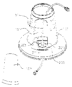
Referring to FIGS. 3 and 4, the heater has a base seat 100 having a bottom
mounted with an isolation plate 200, a pair of semi-stacking male tubes 300,
310 with multiple.corners 301, 31 l, and a screw nut 400 with a circular press
plate 401. The two ends of the isolation plate 200 are connected to the
bottom inner edge of the base seat 100 for securing and the center of the
isolation plate 200 is provided with a recessed sunken seat 201. The sunken
seat 201 is engageable with the corners 301, 311 of the male tubes 300, 310.
The center of the sunken seat 201 is provided with through hole 202 for
mounting with a pair of the semi-stacking male tubes 300, 310. The external
diameter of the male tubes 300, 3 I 0 is smaller than the umbrella hole (not

CA 02461875 2004-03-29
7
shown) on the table surface, and is engageable with the screw nut 400. The
external diameter of the circular press plate 401 of the screw nut 400 is
larger
than the umbrella hole and the surrounding of the screw nut 400 is mounted
radially with a plurality of rotating plates 402, 403, 404, 405 facilitating
rotating with hands. Through holes 406, 407 are provided to the rotating
plates 402, 403, 404, 405. In addition, the surrounding of the base seat 100
is
provided with a hole 101 covered with a fastening cap 102 to facilitate a hand
to be inserted thereto to connect to a gas outlet tube .'i l, or to place a
male
tubes 300, 310 so that the comers 301, 3 I 1 are placed to the sunken seat
201.
As shown in FICx 5, there is shown the structure of the semi-stacking
male tubes 300, 310. The external diameter of the connector 52 of the gas
outlet tube is larger than the tube hole of tubes 300, 310. The tubes 300, 310
can be triggered halfway which can clip the gas outh,~t tube ~ 1 into the hole
of
the tubes 300, 310. As shown in FIGc 6, the tubes 300, 310 are stacked so
that it can be slidably moved the gas outlet tube. As shown in FICA 7, the
base seat 100 is placed onto the table surface 11 of the table 10 and the male
tubes 300, 310 of the tube 51 is inserted into the umbrella hole 20. The
screw nut 400 is pressed against the male tubes 300, 310 such that the bottom
edge of the base seat and the circular press plate 401 clip to the edged wall
of
the umbrella hole. Thus, the heater of the present invention is secured to the

CA 02461875 2004-03-29
table 10. The lower holes 406, 407 allow the tank containing LPG to be
chained to the bottom of the table and the tank will not be toppled.
It will be understood that each of the elements described above, or two or
more together may also find a useful application in other types of methods
differing from the type described above.
While certain novel features of this invention have been shown and
described and are pointed out in the annexed claim, it is not intended to be
limited to the details above, since it will be understood that various
omissions,
modifications, substitutions and changes in the forms and details of the
device
illustrated and in its operation can be made by those skilled in the art
without
departing in any way from the spirit of the present invention.

Representative Drawing
A single figure which represents the drawing illustrating the invention.
Administrative Status

2024-08-01:As part of the Next Generation Patents (NGP) transition, the Canadian Patents Database (CPD) now contains a more detailed Event History, which replicates the Event Log of our new back-office solution.

Please note that "Inactive:" events refers to events no longer in use in our new back-office solution.

For a clearer understanding of the status of the application/patent presented on this page, the site Disclaimer , as well as the definitions for Patent , Event History , Maintenance Fee  and Payment History  should be consulted.

Event History

Description Date
Inactive: IPC expired 2022-01-01
Inactive: Agents merged 2013-10-29
Application Not Reinstated by Deadline 2007-03-29
Time Limit for Reversal Expired 2007-03-29
Deemed Abandoned - Failure to Respond to Notice Requiring a Translation 2006-08-25
Inactive: Incomplete 2006-05-25
Deemed Abandoned - Failure to Respond to Maintenance Fee Notice 2006-03-29
Inactive: IPC from MCD 2006-03-12
Application Published (Open to Public Inspection) 2005-07-06
Inactive: Cover page published 2005-07-05
Inactive: IPC assigned 2004-11-24
Inactive: IPC assigned 2004-11-02
Inactive: First IPC assigned 2004-11-02
Letter Sent 2004-08-19
Revocation of Agent Requirements Determined Compliant 2004-08-16
Inactive: Office letter 2004-08-16
Appointment of Agent Requirements Determined Compliant 2004-08-16
Inactive: Single transfer 2004-07-20
Revocation of Agent Request 2004-07-20
Appointment of Agent Request 2004-07-20
Inactive: Filing certificate - No RFE (English) 2004-04-27
Application Received - Regular National 2004-04-26
Inactive: Filing certificate - No RFE (English) 2004-04-26

Abandonment History

Abandonment Date Reason Reinstatement Date
2006-08-25
2006-03-29

Fee History

Fee Type Anniversary Year Due Date Paid Date
Application fee - small 2004-03-29
Registration of a document 2004-07-20
Owners on Record

Note: Records showing the ownership history in alphabetical order.

Current Owners on Record
GRAND HALL ENTERPRISE CO., LTD.
Past Owners on Record
WILLIAM HOME
Past Owners that do not appear in the "Owners on Record" listing will appear in other documentation within the application.
Documents

To view selected files, please enter reCAPTCHA code :


To view images, click a link in the Document Description column. To download the documents, select one or more checkboxes in the first column and then click the "Download Selected in PDF format (Zip Archive)" or the "Download Selected as Single PDF" button.

List of published and non-published patent-specific documents on the CPD .

If you have any difficulty accessing content, you can call the Client Service Centre at 1-866-997-1936 or send them an e-mail at CIPO Client Service Centre.


Document
Description 
Date
(yyyy-mm-dd) 
Number of pages   Size of Image (KB) 
Abstract 2004-03-28 1 38
Description 2004-03-28 7 255
Drawings 2004-03-28 5 109
Claims 2004-03-28 2 49
Representative drawing 2005-06-07 1 10
Filing Certificate (English) 2004-04-26 1 158
Courtesy - Certificate of registration (related document(s)) 2004-08-18 1 105
Reminder of maintenance fee due 2005-11-29 1 110
Courtesy - Abandonment Letter (Maintenance Fee) 2006-05-23 1 175
Courtesy - Abandonment Letter (incomplete) 2006-09-17 1 167
Correspondence 2004-04-25 1 34
Correspondence 2004-07-19 2 73
Correspondence 2004-08-15 1 15
Correspondence 2004-08-15 1 17
Correspondence 2006-05-24 1 18