Note: Descriptions are shown in the official language in which they were submitted.
CA 02462068 2004-03-24
-1-
Title: A BICYCLE HAVING INTERNALLY ROUTED CONTROL CABLES
Field of the invention
[0001] The subject invention relates to internally supporting bicycle
control cables, and more specifically to routing control cables through
various
components of all types of bicycles including, but not limited to, standard,
racing and mountain bikes and to headsets for bicycles.
Background of the invention
[0002] Bicycles have been utilized as a means of transportation for
over a hundred years and continue to grow in popularity. The mountain bike is
one type of bike that has become more and more popular in recent years.
These types of bikes are often used in rough terrain.
[0003] Operational or control cables typically extend from control
levers, often secured to the bicycle handlebars, used to control both front
and
back wheel braking capacities and front and back shifting mechanisms such
as the front and rear derailleurs. The operational or control cables are
normally mounted along the outside of the tubular frame members, with
various attachment members, such as clips. The cables can interfere with
either the rider or other components of the bicycle, such as tool
compartments, which are also attached to the frame exterior. In the case of
mountain bikes, externally located cables are susceptible to damage from the
surrounding environment, such as tree branches. Further, the cables also
detract from the aesthetic appearance of the frame, as they may cover art or
graphic logos on the bike frame.
[0004] To eliminate the appearance of cables on the exterior of bicycle
frames, prior art attempts have been made to extend the cables through the
interiors of tubular frame components. An early example is described in
French Patent No. 982,877, which shows a bicycle frame in which the top
tube consists of a hollow, tubular member having a forward cable outlet at a
location near the head tube socket which is attached to the top tube, and a
rearward cable outlet adjacent to the seat mast of the bicycle frame. A later
example is described in German Patent Application No. 19712326, where at
CA 02462068 2004-03-24
-2-
least one section of the base frame has an extruded profile tube section with
at least one channel to accept a cable.
[0005] While the internal cable system of this type of frame eliminates
the appearance of the cable on the exterior of the frame components, the
forming of several openings along the top tube of a bicycle frame tends to
weaken the wall of that tube, which would require either that the tube be made
of a strong but heavy material such as steel, or that the tube walls be
thickened if made of a relatively light material which would also add to the
overall weight of the frame.
[0006] A more recent example of an internal cable routing system can
be found in United States Patent Number 5,478,100, where the cables are
located inside of the top tube or down tube. However, the cables are still
exposed from the brake or shift levers until they are routed into the frame
some distance away.
[0007] In United States Patent Number 4,768,798, the cables are
routed directly into the frame at a point in front of the steering axis. In
this
case, the cables are also exposed until they reach the frame. In addition, the
complexity of the steering tube is increased so that the cables can be routed
through the tube and not interfere with the steering mechanism.
[0008] In recent years, it has also become recognized that the old-
fashioned stationary handlebar and stem bicycle configuration can cause
health problems such as lower back pain and wrist pain, due to the crouched
body position necessary during bike riding. Many issued patents claim bicycle
handlebars or stems that can be adjusted in one manner or another. United
States Patent Numbers 5,133,224, 5,273,302, 5,456,135, 5,727,427 and
5,737,967 describe various systems for adjusting bicycle handlebars or
bicycle stems. However, these prior art adjustable handlebar stems would
interfere with any internal cable routing system.
[0009] Accordingly, there is a need for an internal cable system for a
bicycle frame that does not interfere with the steering mechanism and does not
CA 02462068 2004-03-24
-3-
compromise the structural integrity of the tubes housing the cable, while
permitting adjustable handlebars or stems.
Summary of the invention
[0010] In one aspect, the present invention is an internal control cabling
system that does not interfere with the steering mechanism and does not
compromise the structural integrity of the bicycle frame. In the disclosed
internal control cable system, the control cables are routed through the
interiors of the handlebar stem or gooseneck and, optionally, one or more
parts of the bicycle frame, such as a head or steering tube, to the mechanism
or device that they are designed to control. The headset design is unique in
that it allows for one or more of, an unobstructed passageway for the cables
to travel into the steering tube of the frame; sliding of the handlebar
forward or
rearward; raising and lowering of the handlebar, as desired by the bicycle
rider. For aesthetic reasons, a casing can be added to cover the cabling
between the control levers and the gooseneck. In other aspects, the invention
provides one or more parts for a headset such as a fork with a fork yoke, a
handlebar stem adapted to be inserted into the fork yoke and a handlebar
adapted to be attached to the handlebar stem. Connections between these
components permit internal passageways in the handlebar stem and fork yoke
to remain open or permit the arrangement of at least one of these
components to be adjusted relative to another. The description above is
intended only to introduce the reader to the invention and other aspects of
the
invention may lie in a combination or sub-combination of elements described
above or in other parts of this patent, or as described in the claims.
Brief descriation of the drawincrs
[0011] Other advantages of the present invention will be readily
appreciated as the same becomes better understood by reference to the
following detailed description when considered in connection with the
accompanying drawings of an exemplary embodiment wherein:
[0012] Figure 1 is a side view of a bicycle, which illustrates the
preferred embodiment of the invention;
CA 02462068 2004-03-24
-4-
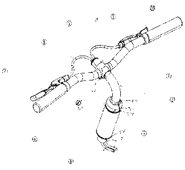
[0013] Figure 2 is an isometric view of the handle bar and stem
gooseneck assembly without the casing;
[0014] Figure 3 is a side view of the handle bar and stem gooseneck
assembly without the casing;
[0015] Figure 4 is a cross-sectional view of the handle bar and stem
gooseneck assembly similar to that of Figure 3, illustrating the internal
cabling; and
[0016] Figure 5 is an isometric view of the handlebars and stem
gooseneck, fully assembled with the casing.
Detailed description of the invention
[0017] Referring to the Figures, wherein like numerals indicate like or
corresponding parts throughout the several views, the preferred embodiment
of the invention consists of a bicycle 100 having a frame 26 that includes a
head tube or steering head 6 that is adapted to receive a handlebar stem 2 in
its upper end 70 and a fork stem or yoke 12 of a fork 14 through its lower end
72. In the preferred embodiment, the handlebar stem 2 is adjustable and may
be referred to as a "gooseneck". The particular gooseneck 2 described herein
is an open-ended tube bent so that, with a first end 16 of the gooseneck 2
oriented substantially vertically, a second end 18 of the gooseneck 2 is at an
angle from the vertical of greater than 45 degrees. In a preferred embodiment,
the angle between the two ends 16, 18 of the handlebar stem is substantially
90 degrees, or perpendicular.
[0018] As best seen in Figure 4, but with reference to the other Figures,
the bicycle 100 has a headset 50 that includes the fork 14, handlebar stem 2,
handlebar 1, connectors between those components and connectors between
the headset 50 and the head tube 6. The head tube 6 has a counter bore 52
on each of its upper and lower ends, each counter bore 52 holding a bearing
assembly 54. A fork ring 11 is fitted over a bottom end 58 of the fork yoke 12
and rests on a fork bridge 15. The fork 14 slides into the lower end 70 of the
head tube 6 so that the fork bridge 15 bears on the fork ring 11 which in turn
CA 02462068 2004-03-24
-5-
bears on the lower bearing assembly 54. The fork bridge 15 is attached to the
outside of the fork yoke 12 so as to not close an opening in the bottom end 58
of the fork yoke 12 to an internal passageway 56 through the fork yoke 12.
The top end 60 of the fork yoke 12 protrudes above the upper end 70 of the
head tube 6 and is externally threaded and split with two longitudinal slits
(not
labeled). The top end 60 of the fork yoke 12 is open and receives the first
end
16 of the handlebar stem 2. A head locking collar 30 is internally threaded
and screwed onto the upper end 70 of the fork yoke 12. An abutment 74 on
the bottom of the head locking collar 30 bears on the bearing assembly 54 in
the upper end 70 of the head tube 6 to compress the bearing assemblies 54
and hold the fork 14 in the head tube 6. Head locking collar 30 is split with
a
vertical slit that may be closed with a head collar bolt 31. When the head
collar bolt 31 is tightened, the slits in both head locking collar 30 and the
top
end 60 of the fork yoke 12 are closed. This compresses the top end 60 of the
fork yoke 12 about the first end 16 of the handlebar stem 2. In this way, the
fork 14 and handlebar stem 2 are frictionally connected together without
closing an internal passageway 62 through the handlebar stem 2 or the
internal passageway 56 through the fork yoke 12. The head locking collar 30
is also secured in position on the fork yoke 12 to preserve the desired
compression on the bearing assemblies 54.
[0019] As best seen in Figures 2, 3 and 4, the handlebar stem or
gooseneck 2 and handle bar 1 are attached by a handle bar locking collar 5,
which is tightened by means of a handle bar collar bolt 10. The proposed
arrangement has the advantage of allowing the handle bar 1 to have up/down
and fore/aft adjustment to suit a variety of rider sizes and preferences.
Referring to Figure 3, if head collar bolt 31 is loosened in order to free
head
locking collar 30, then the handle bar 1 and gooseneck 2 assembly can be
moved in the direction of the axis of steering head 6, that is substantially
in
the vertical or up/down direction. If the handle bar collar bolt 10 is
loosened,
then the handle bar locking collar 5 will loosen such that the handle bar 1
can
be moved along the gooseneck 2, providing for substantially fore/aft
adjustment of the handle bar 1. The handle bar locking collar 5 connects to
CA 02462068 2004-03-24
-6-
the outside of the handlebar stem 2 and so does not close the open second
end 18, or the internal passageway 62 of the handlebar stem 2 which may
extend forward beyond handle bar locking collar 5.
[0020] In the preferred embodiment, first control cable 8, which controls
the front derailieur 25, is controlled by first lever 7. Second control cable
9,
which controls the rear brake 24, is controlled by second lever 28. The cables
pass through the bent stem gooseneck 2. The cables 8, 9 pass out of the
bottom of the gooseneck 2, such that the gooseneck 2 acts as a cable
conduit, and also out of the bottom of the steering head 6. The cables 8, 9
are
then routed into the frame 26 of the bicycle 100 through opening 21. It is
obvious to someone skilled in the art that multiple openings could be used on
the gooseneck 2 or the frame 26. The cables 8, 9 are then routed through the
frame 26 to the mechanism or device that they are meant to control.
(0021] In the disclosed embodiment, first control cable 8 is routed into
the interior of stem gooseneck 2, steering head 6 and then through the
interior
of frame 26 via an entrance hole 21, and exits through opening 22, where the
cable 8 is then attached to its associated control mechanism, the front
derailleur 25. Similarly, the second control cable 9 is routed into the
interiors
of stem gooseneck 2, steering head 6 and then through the interior of frame
26 via an entrance hole 21, and exits through opening 23, where it is attached
to its associated control mechanism, the rear brake 24. The control cables 8,
9 are able to pass through the gooseneck 2 unhindered and without
interfering with the steering mechanism, as the gooseneck 2 is essentially an
open cable conduit. In passing from the down tube to the seat tube of the
frame 26, the cables 8, 9 may exit the frame 26 through an additional opening
in the down tube and re-enter the frame 26 through an additional opening in
the seat tube. Alternately, the cables 8, 9 may pass through the interior of
the
bottom bracket of the frame 26 or a portion of the down tube or seat tube
extending outside of the bottom bracket.
[0022] For aesthetic reasons, the handle bar 1, gooseneck 2 and
cables 8, 9 in the region of the handle bar 1, may be covered with a casing 27
CA 02462068 2004-03-24
_7_
as illustrated in Figure 5. In this embodiment, the casing 27 is constructed
in a
clamshell manner having both an upper half 41 and lower half 42. The two
halves 41, 42 can be secured to the handlebar 1 by bolting the two halves 41,
42 together around the handlebar 1, for example. Any other suitable means
may be used, including bonding, welding, or riveting the halves together.
Alternately, the casing 27 can be attached to the handlebar 1 and handlebar
stem 2 directly or by means of intermediate brackets or components.
[0023] In a further embodiment, additional accessories can be added to
the casing 27, such as a speedometer 29, as shown in Figure 5. Optionally,
any cables associated with the speedometer 29 can be routed through the
gooseneck 2 and either into the frame 26 or down the front forks 14 to the
speedometer sensor, not shown.
[0024] While the form of apparatus described herein constitutes a
preferred embodiment of this invention, it is to be understood that the
invention
is not limited to this precise form of apparatus. For example, additional
control
cables, levers and derailleurs, brakes, electric wires, or other systems can
be
included. The frame 26 may also be a different sort of frame, such as a
monocoque frame. The components of the headset 50 may be modified in
various ways. . Further, the casing 27 may not be a clamshell design. These
and other modifications may still be within the scope of the invention
protected
by this patent which is defined by the following claims.