Language selection

Search

Patent 2462287 Summary

Third-party information liability

Some of the information on this Web page has been provided by external sources. The Government of Canada is not responsible for the accuracy, reliability or currency of the information supplied by external sources. Users wishing to rely upon this information should consult directly with the source of the information. Content provided by external sources is not subject to official languages, privacy and accessibility requirements.

Claims and Abstract availability

Any discrepancies in the text and image of the Claims and Abstract are due to differing posting times. Text of the Claims and Abstract are posted:

  • At the time the application is open to public inspection;
  • At the time of issue of the patent (grant).
(12) Patent: (11) CA 2462287
(54) English Title: LATERALLY ADJUSTABLE CLAMP
(54) French Title: COLLIER DE SERRAGE A REGLAGE LATERAL
Status: Term Expired - Post Grant Beyond Limit
Bibliographic Data
(51) International Patent Classification (IPC):
  • F16L 03/12 (2006.01)
  • F16B 43/00 (2006.01)
  • F16L 03/123 (2006.01)
  • F16L 55/035 (2006.01)
(72) Inventors :
  • MESSINGER, STANLEY KENNETH (United States of America)
(73) Owners :
  • BELL HELICOPTER TEXTRON, INC.
(71) Applicants :
  • BELL HELICOPTER TEXTRON, INC. (United States of America)
(74) Agent: SMART & BIGGAR LP
(74) Associate agent:
(45) Issued: 2010-12-14
(22) Filed Date: 2004-03-25
(41) Open to Public Inspection: 2004-10-09
Examination requested: 2009-03-09
Availability of licence: N/A
Dedicated to the Public: N/A
(25) Language of filing: English

Patent Cooperation Treaty (PCT): No

(30) Application Priority Data:
Application No. Country/Territory Date
10/410,797 (United States of America) 2003-04-09

Abstracts

English Abstract

A clamp that is laterally positionable with respect to a fastener includes a clamp body including a pair of opposable legs. Each of the legs includes an elongated hole adapted to movably engage the fastener. One of the legs includes a locking surface. A locking washer is engageable with the locking surface of the clamp body leg. The locking washer includes a hole that is adapted to fixedly engage the fastener. When engaged with the fastener, the locking washer fixes the lateral position of the clamp body with respect to the fastener.


French Abstract

Collier de serrage qui se place latéralement par rapport à une pièce de fixation, comprenant un collier de serrage et une paire de pattes opposées. Chacune des pattes comporte un trou allongé conçu pour loger la pièce de fixation et lui permettre de bouger. Une des pattes comprend une surface de blocage. Une rondelle de blocage peut se fixer à la surface de blocage de la patte du collier de fixation. La rondelle de blocage comporte un trou conçu pour fixer la pièce de fixation. Lorsqu'elle est fixée à la pièce de fixation, la rondelle de blocage maintient la position latérale du collier de fixation par rapport à la pièce de fixation.

Claims

Note: Claims are shown in the official language in which they were submitted.

5
WHAT IS CLAIMED IS:
1. A clamp, which comprises:
a clamp body including a pair of opposable legs, one of said legs including a
locking plate, each of said legs and said locking plate including an elongated
hole
adapted to movably engage a fastener, said elongated hole having a length and
a
width, said locking plate including a plurality of locking members spaced
apart along
the length of said elongated hole; and,
a locking washer lockingly engageable with said locking plate, said locking
washer having a hole adapted to fixedly engage said fastener said locking
washer
including at least one locking member matingly engageable with locking members
of
said locking plate, thereby locking said clamp body to said fastener at one of
a
plurality of faced positions along said elongated hole.
2. The clamp as claimed in claim 1, wherein said locking plate is affixed to
said
one of said legs.
3. The clamp as claimed in claim 1, wherein said hole of said locking washer
is
substantially circular.
4. The clamp as claimed in claim 3, wherein said width of said elongated hole
is
substantially equal to the diameter of said hole of said locking washer.
5. The clamp as claimed in claim 1, including a clamp cushion affixed to a
portion of said clamp body.
6. The clamp as claimed is claim 5, wherein said clamp cushion is elastomeric.
7. The clamp as claimed in claim 1, including means for locking together said
legs.

6
8. The clamp as claimed in claim 7, wherein said means for locking together
said legs comprises a tab on one of said legs engageable with a hole on the
other of
said legs.
9. The clamp as claimed in claim 1, wherein said locking members of said
locking plate are defined by a serrated surface.
10. The clamp as claimed in claim 9, wherein said locking washer includes a
serrated surface engageable with the serrated surface of the locking plate.
11. A clamp, which comprises:
a clamp body including a pair of opposable legs, each of said legs including
an elongated hole having a length and a width adapted to movably engage a
fastener
along said length of said elongated hole, one of said legs including a locking
surface
including a plurality of locking members extending along said length of said
elongated hole; and,
a locking washer including a locking member engageable with said at least
one of said locking members of said locking surface of said one of said legs
of said
clamp body, said locking washer having a hole adapted to fixedly engage a said
fastener, thereby locking said clamp body to said fastener at one of a
plurality of
faced position along said elongated hole.
12. The clamp as claimed in claim 11, wherein said hole of said locking washer
is substantially circular.
13. The clamp as claimed in claim 12, wherein said elongated holes of said
legs
have a length and a width, said width being substantially equal to the
diameter of
said hole of said locking washer.

7
14. The clamp as claimed in claim 11, including a clamp cushion affixed to a
portion of said clamp body.
15. The clamp as claimed in claim 14, wherein said clamp cushion is
elastomeric.
16. The clamp as claimed in claim 11, including means for locking together
said
legs.
17. The clamp as claimed in claim 16, wherein said means for locking together
said legs comprises a tab on one of said legs engageable with a hole on the
other of
said legs.
18. The clamp as claimed in claim 11, where said locking surface is defined by
a
locking plate affixed to said one of said legs.
19. The clamp as claimed in claim 11, wherein said locking members of said
locking
surface are defined by a serrated surface and said locking member of said
locking
washer is defined by a serrated surface engageable with said serrated surface
of said
locking surface.
20. A clamping system, which comprises:
a fastener,
a clamp body, said clamp body including a pair of opposable legs; each of
said legs including an elongated hole having a length and a width, said legs
being
adapted to movably engage said fastener along the length of said elongated
hole, one
of said legs including a locking surface including a plurality of laterally
spaced apart
locking members extending along the length of said elongated hole; and,
a locking washer including at least one locking member engageable with said
at least one of said locking members of said locking surface, said locking
washer

8
having a hole adapted to fixedly engage said fastener, thereby fixing said
clamp body
laterally at one of a plurality of fixed positions with respect to said
fastener.
21. The clamping system as claimed in claim 20, wherein said fastener includes
a
bolt.
22. The clamping system as claimed in claim 20, wherein said fastener includes
a
stud.
23. The clamping system as claimed in claim 20, wherein said fastener includes
a
substantially circular portion and said hole of said locking washer is
substantially
circular having a diameter substantially equal to the diameter of the circular
portion
of said fastener.
24. The clamping system as claimed in claim 23, wherein said elongated holes
of
said legs have a length and a width, said width being substantially equal to
the
diameter of said hole of said locking washer.
25. The clamping system as claimed in claim 20, including a clamp cushion
affixed to a portion of said clamp body.
26. The clamping system as claimed in claim 25, wherein said clamp cushion is
elastomeric.
27. The clamping system as claimed in claim 20, including means for locking
together said legs.
28. The clamping system as claimed in claim 27, wherein said means for locking
together said legs comprises a tab on one of said legs engageable with a hole
on the
other of said legs.

9
29. The clamping system as claimed in claim 20, wherein said locking surface
is
defined by a locking plate affixed to said one of said legs.
30. The clamping surface as claimed in claim 20, wherein said locking members
of said locking surface include a plurality of serrations on said locking
surface and
said locking member of said locking washer includes at least one serration
engageable with a serration of said locking surface.

Description

Note: Descriptions are shown in the official language in which they were submitted.


tt
CA 02462287 2004-03-25
LATERALLY ADVUSTABLE CLAMP
C~,QVERS111~NT RIGHTS STATE
This invention was made with Government support under Contract No.
N00019-93-C-0006 awarded by the Department of the Navy. The Government has
certain rights in this invention.
F1ELD OF THE INVENTION
The present invention relates generally to the field of clamps, and more
particularly to a laterally adjustable P-type clamp.
BACKGROUND OF THE IIWENTION
One common way to secure conduits such as hoses, pipes, hydraulic lines,
electrical cables and the like to structures is by means of P-clamps. A P-
G'lamp
generally comprises a circular clamp body and a pair of opposable legs
connected to
the clamp body. The opposable legs usually have therein circular holes that
are
engageable with a fastener such as a bolt or screw or a stud. In operation,
the clamp
body is clamped around the article to be secured and the P-clamp is secured to
the
structure by engaging the hole in the legs with a fastener secured to the
structure.
One way in which P-clamps are secured to structures is by means of click
studs. A click stud includes a threaded member crnmected to a plate. The plate
is
bonded to the structure. A problem with click studs is that they should be
positioned
relatively precisely with respect to the article being secured. If the click
stud is not
positioned within a relatively narrow tolerance, the conduit such as a
hydraulic line
to which the P-clamp is secured can exert a rather substantial side load on
the click
stud The side load can cause the click stud to become disbonded from the
structure.
The disbonding problem can be particularly acute in high vibration
environments.

CA 02462287 2004-03-25
r
2
~Uf~ARY QF~ ll~iVENTIQN
The present invention provides a clamp that is laterally positionable with
respect to a fastener. The clamp of the present invention includes a clamp
body
including a pair of opposable legs. Each of the legs includes an elongated
hole
adapted to movably engage the fastener. One of the legs includes a locking
surface.
A locking washer is engageable with the locking surface of the clamp body leg.
The
locking washer includes a hole that is adapted to fixedly engage the fastener.
When
engaged with the fastener, the locking washer fixes the position of the clamp
body
with respect to the fastener.
BRIEF D~'ION OF THE DRAWINGS
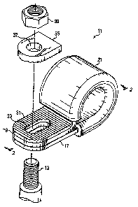
Figure 1 is an exploded view of a clamp according to the present invention.
Figure 2 is a sectional view taken along line 2-2 of Figure 1.
Figure 3 is an ticploded view of as alternative clamping system according to
the present invention.
Figure 4 is a pave view a portion of a clamp according to the present
invention without a serrated top plate and serrated washer.
DES ~TION OF THE ~$~~FERRED EN18OD1141ENT
Referring now to the drawing, and first to Figures 1 and 2, a clamp
according to the present invention is desigriatod generally by the numeral 11.
Clamp
11 is adapted to attach a conduit such as a hydraulic line, electric cable or
the like
(not shown) to a stud 13.
Clamp 11 includes a generally circular clamp body 15 and a pair of
opposable legs 17 and 19. Clamp body 15 is preferably covered with an
elastomeric
sheath 21.
Legs 17 and 19 each have an elongated hole 23 and 25, respectively, therein.
The widths of holes 23 and 25 are substantially equal to the diameter of stud
13. The
lengths of holes 23 and 25 are longer than the diameter of stud 13.
Accordingly,
clamp 11 may be moved laterally back and forth with respect to stud 13. Leg 19
30141276v1

CA 02462287 2004-03-25
3
may include a tab 27 that is engageable with a slot 29 in leg 17. Engagement
of tab
27 with slot 29 locks together legs 17 and 19 to prevent them from moving
laterally
with respect to each other.
I,eg 19 has affixed thereto a serrated locking plate 31. Plate 31 has therein
an
elongated hole 33, having substantially the same dimensions as holes 23 and 25
and
legs 17 and 19, respectively. Hole 33 of plate 31 is aligned with hole 25 in
leg 19.
A serrated locking washer. 35 is engageable with serrated plate 31. Washer
35 has a plurality of serrations that are mateable with the aerrations of
plate 33.
Washer 35 also has a round hole 37 therein. The diameter of hole 37 is
substantially
the same as the diameter of the threaded portion of stud 13. Accordingly,
serrated
washer 35 is laterally immoveable with respect to stud 13.
In operation, clamp body 15 is clamped around an article such as an
hydraulic line to be secured to stud 13. After clamp body 15 is clamped around
the
article, legs 17 and 19 are brought generally into engagement with each other
with
tab 27 engaging slot 29. Then, legs 17 and 19 are engaged with the threaded
portion
of stud 13 with the threaded portion extending through elongated holes 23, 25
and 33.
Since holes 23, 25 and 33 are elongated, clamp 11 is positioned laterally with
respect
to stud 13 such that no preload is applied to the article clamped in clamp
body 15.
Then, serrated washez 35 is slipped over the threaded portion of stud 13 and
into
engagement with serrated plate 31, When a nut 39 is made up with stud 13,
clamp
11 becomes locked laterally with respect to stud 13. Thus, clamp 11 clamps an
article such as a hydraulic line with respect to a stud 13 without exerting
lateral force
on the clamped article: The clamp according to the present invention allows
for
reduced tolerances with respect to the placement of studs 13 and clamped
articles.
As illustrated in Figure 3, clamp 11 may also be used with a bolt or screw 41
instead of a stud 13. The bolt 41 may be attached to a structure or bracket
(not
shown) with a nut or nut plate. In Figure 4, there is illustrated a clamp 11
without
serrated plate 31. Serrated plate 31 is affixed to leg 19 in any of several
well known
methods for affixing metal articles to each other. In an alternative
embodim~t, an
upper surface of leg 19 may be serrated to elimibate a separate serrated plate
31.
a~mn

CA 02462287 2004-03-25
s
4
The present invention has bees illustrated and described with respect to
presently preferred embodiments. Those skilled in the art will recognize
alternative
embodiments given the benef t of the foregoing disclosure. Accordingly, the
foregoing is mended for proposes of illustration rather than limitation.
mrm

Representative Drawing
A single figure which represents the drawing illustrating the invention.
Administrative Status

2024-08-01:As part of the Next Generation Patents (NGP) transition, the Canadian Patents Database (CPD) now contains a more detailed Event History, which replicates the Event Log of our new back-office solution.

Please note that "Inactive:" events refers to events no longer in use in our new back-office solution.

For a clearer understanding of the status of the application/patent presented on this page, the site Disclaimer , as well as the definitions for Patent , Event History , Maintenance Fee  and Payment History  should be consulted.

Event History

Description Date
Inactive: Expired (new Act pat) 2024-03-25
Common Representative Appointed 2019-10-30
Change of Address or Method of Correspondence Request Received 2018-01-12
Inactive: Agents merged 2015-11-05
Grant by Issuance 2010-12-14
Inactive: Cover page published 2010-12-13
Pre-grant 2010-10-01
Inactive: Final fee received 2010-10-01
Letter Sent 2010-04-12
Notice of Allowance is Issued 2010-04-12
Inactive: Approved for allowance (AFA) 2010-03-31
Amendment Received - Voluntary Amendment 2009-05-27
Letter Sent 2009-04-24
All Requirements for Examination Determined Compliant 2009-03-09
Request for Examination Received 2009-03-09
Request for Examination Requirements Determined Compliant 2009-03-09
Inactive: IPC from MCD 2006-03-12
Application Published (Open to Public Inspection) 2004-10-09
Inactive: Cover page published 2004-10-08
Inactive: First IPC assigned 2004-09-20
Inactive: IPC assigned 2004-09-20
Revocation of Agent Requirements Determined Compliant 2004-07-08
Inactive: Office letter 2004-07-08
Appointment of Agent Requirements Determined Compliant 2004-07-08
Revocation of Agent Request 2004-05-20
Appointment of Agent Request 2004-05-20
Inactive: Filing certificate - No RFE (English) 2004-04-28
Letter Sent 2004-04-28
Application Received - Regular National 2004-04-28

Abandonment History

There is no abandonment history.

Maintenance Fee

The last payment was received on 2010-03-03

Note : If the full payment has not been received on or before the date indicated, a further fee may be required which may be one of the following

  • the reinstatement fee;
  • the late payment fee; or
  • additional fee to reverse deemed expiry.

Patent fees are adjusted on the 1st of January every year. The amounts above are the current amounts if received by December 31 of the current year.
Please refer to the CIPO Patent Fees web page to see all current fee amounts.

Owners on Record

Note: Records showing the ownership history in alphabetical order.

Current Owners on Record
BELL HELICOPTER TEXTRON, INC.
Past Owners on Record
STANLEY KENNETH MESSINGER
Past Owners that do not appear in the "Owners on Record" listing will appear in other documentation within the application.
Documents

To view selected files, please enter reCAPTCHA code :


To view images, click a link in the Document Description column (Temporarily unavailable). To download the documents, select one or more checkboxes in the first column and then click the "Download Selected in PDF format (Zip Archive)" or the "Download Selected as Single PDF" button.

List of published and non-published patent-specific documents on the CPD .

If you have any difficulty accessing content, you can call the Client Service Centre at 1-866-997-1936 or send them an e-mail at CIPO Client Service Centre.

({010=All Documents, 020=As Filed, 030=As Open to Public Inspection, 040=At Issuance, 050=Examination, 060=Incoming Correspondence, 070=Miscellaneous, 080=Outgoing Correspondence, 090=Payment})


Document
Description 
Date
(yyyy-mm-dd) 
Number of pages   Size of Image (KB) 
Abstract 2004-03-24 1 17
Description 2004-03-24 4 157
Claims 2004-03-24 5 157
Drawings 2004-03-24 2 70
Representative drawing 2004-09-15 1 11
Courtesy - Certificate of registration (related document(s)) 2004-04-27 1 105
Filing Certificate (English) 2004-04-27 1 158
Reminder of maintenance fee due 2005-11-27 1 110
Reminder - Request for Examination 2008-11-25 1 117
Acknowledgement of Request for Examination 2009-04-23 1 175
Commissioner's Notice - Application Found Allowable 2010-04-11 1 166
Correspondence 2004-05-19 3 67
Correspondence 2004-07-07 1 13
Correspondence 2004-07-07 1 16
Correspondence 2010-09-30 1 37
Correspondence 2011-01-25 17 356