Note: Descriptions are shown in the official language in which they were submitted.
CA 02462556 2004-04-O1
WO 03/035120 PCT/ITO1/00538
DESCRIPTION
PRESSURIZATION DEVICE
The present invention relates to a pressurization device, in
particular of the type used for high hydrostatic pressure.
There are various methods of sterilizing/pasteurizing foods
and their containers.
A first method provides for the sterilization of the foods
or beverages by a heat treatment and for their packaging at
high temperature in order to utilize their thermal energy as .
an agent for sterilizing the container. This method can be
used with containers the physical/chemical characteristics
of which. do not change at the filling temperature, and is
generally used with glass or aluminium containers (cans) or
with recrystallized PET containers.
A second method provides for the sterilization of the foods
by a heat treatment prior to packaging which is then carried
out at ambient temperature, in an aseptic chamber, in a
previously sterilized container. This system presupposes
the sterilization of the container with chemical/physical
agents and the maintenance of an aseptic environment during
the packaging and sealing stage with the use of suitable
sterile chambers (known as "white chambers") having a volume
of a few cubic meters, which chambers are difficult to
control in an industrial environment.
The spread, in recent years, of new dietary products and
products to which vitamins and/or microelements important
for supplementing the diet have been added has given rise to
the need to provide alternative sterilization methods to
CA 02462556 2004-04-O1
WO 03/035120 PCT/ITO1/00538
2
those using heat so as to avoid irreversible processes which
denature the product.
Amongst the various methods used - the use of pulsed
electric fields, magnetic fields, microwaves etc. - the
method based on the use of hyperbaric chambers, in which
sterilization is achieved by the maintenance of high
hydrostatic pressure, has recently gained particular
importance. Tt is known that the application of high.
pressure induces morphological changes in the cells of
micro-organisms, which may extend to rupture of the cell
membrane and consequent death of the micro-organism.
The extent and early occurrence of the changes induced lay
the high pressure depend on various factors, amongst which
are the intensity of the pressure, the time for which it is
applied, and the type of compression/decompression cycle
used.
The use of the hydrostatic-pressure sterilization method in
the food industry is known. However, the method has the
disadvantage of being discontinuous since it provides for
the use of large hyperbaric chambers in which a batch of
products to be sterilized is inserted. Moreover, a.t is
characterized by long sterilization-cycle times which are
due partly to the time required by the apparatus to reach
the working pressure and to return to atmospheric pressure
upon completion. The known method therefore clearly has
little versatility and does not permit adequate productivity
of the plant.
To prevent these problems, apparatus has been proposed for
the sterilization of beverages at high pressure, fox which
continuous, linear or rotary apparatus is provided and
CA 02462556 2004-04-O1
WO 03/035120 PCT/ITO1/00538
3
comprises a plurality of high-pressure sterilization
chambers, each of which can hold one bottle. This solution
is covered by European patent application EP 1 048 608
published on 2nd November 2000.
Although this apparatus substantially solves the problems
inherent in the apparatus and methods of the prior art, it
has some disadvantages. In fact, the operation of the
sterilization device as conceived in the above-mentioned
patent application is complex, particularly with regard to
the kinematic mechanism for the insertion of the bottles in
the device and their removal therefrom..
A further disadvantage of known apparatus operating at
pressures of a few thousand atmospheres is connected with
the difficulty of ensuring effective and durable sealing of
the pressurization chamber. In particular, the seals are
subject to wear such as to require their replacement after a
few weeks of continuous working, which requires the use of
expensive special seals.
The problem underlying the present invention is therefore
that of providing a pressurization device which overcomes
the disadvantages set out above.
This problem has been solved by a pressurization device as
defined in the appended claims.
Further characteristics and advantages of the pressurization
device of the present invention will become clearer from the
description of some preferred embodiments thereof, given
below by way of non-limiting example, with reference to the
appended drawings, in which:
CA 02462556 2004-04-O1
WO 03/035120 PCT/ITO1/00538
4
Figure 1 is a perspective view of the pressurization device
of the invention in the non-operative condition,
Figure 2 is a side view showing the device of Figure 1 in
section,
Figures 3a, 3b, 3c, 3d are views all showing, in section,
the same detail of the device of Figure 1, in accordance
with an operative sequence, and
Figure' 4 shows, in section, a detail of a different
embodiment of the pressurization device of the invention.
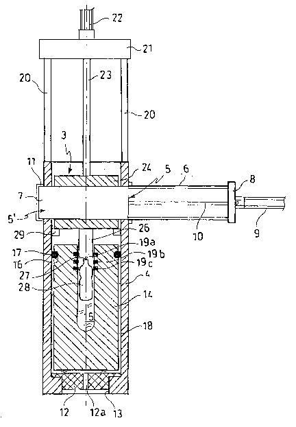
With reference to the drawings, the pressurization device
according to the invention, generally indicated 1,
comprises, basically, a hollow body 2 and a cover 3
connected movably to the body 2.
As shown in Figures 1 and 2 , the hollow body 2 comprises a
substantially cylindrical casing 4 which is open at its two
ends. Two aligned holes 5, 5~ are formed in the cylindrical
lateral surface of the casing 4, in the portion close to its
upper end which is to receive the cover 3.
A .cylindrical guide 6 for a pin 7 for securing the cover 3
is fixed to the first hole 5, as will be explained further
in the following description. The end of the guide 6 which
is inside the casing 4 is open, whereas its outer, opposite
end is closed by a closure disk 8. An actuator 9,
preferably a linear actuator, more preferably a brushless
motor or an oleodynamic cylinder, is mounted externally on
the disk 8. The disk 8 has a central hole through which the
shaft 10 of the actuator 9 extends and, in turn, is fixed to
the outer end of the pin 7.
CA 02462556 2004-04-O1
WO 03/035120 PCT/ITO1/00538
Fixed to the second hole 5' , on the other hand, is a sleeve
11 having its outer end closed and its inner end open.
The inside diameters of the guide 6 and of the sleeve 11 are
substantially equal and correspond to the diameter of the
pin 7 so as to allow the pin to slide inside them.
Moreover, the guide 6 and the sleeve 11 lie on ,the same
axis, which is substantially perpendicular to the principal
axis of the casing 4.
The casing 4 is sealed at the bottom by a cylindrical
closure element 12 with a T-shaped cross-section which has
its larger base bearing on an annular shoulder 13 formed in
the region of the lower end of the casing 4 and which
projects inwardly. A duct 12a extends through the closure
element 12 and is connected externally to a hydraulic system
(not shown in the drawing) which, in the embodiment
described herein, constitutes the pressurization means of
the device.
A hollow pressurization cylinder 14, open at its upper end,
is arranged in a floating condition inside the casing 4 so
that a pressurization chamber 15 is defined within the
cylinder 14.
An annular seal 17 is disposed in a corresponding seat 16 on
the outer lateral surface of the pressurization cylinder 14,
in the vicinity of its upper end. The outside diameter of
the pressurization cylinder l4 is less than the inside
diameter of the casing 4 so as to define a space 18 which is
intended to be filled up to the level of the annular seal 17
with hydraulic oil or other substantially incompressible
fluid.
CA 02462556 2004-04-O1
WO 03/035120 PCT/ITO1/00538
6
Three annular seals 19a, 19b, 19c are arranged in series in
suitable seats on the inner surface of the pressurization
cylinder 14, in the vicinity of its open upper end. The
relative distances D1, D2 between the first and second
annular seals 19a, 19b and between the second and third
annular seals 19b, 19c, respectively, are calibrated on the
basis of the coefficient of compressibility of the fluid
admitted to the pressurization chamber 15 so as to
correspond to predetermined pressure increments, as will be
described further below.
Two rods 20, extending upwards, are fixed to the upper edge
of the casing 4. The upper ends of the rods 20 are fixed to
a plate 21 to the upper surface of which an actuator 22,
preferably a linear actuator, is fixed. The plate 21 has a
hole in the region of the shaft 23 of the actuator 22 which
thus protrudes below the plate 21.
The shaft 23 of the actuator 22 is fixed to the upper
surface of the cover 3.
The body 24 of the cover 3 has a transverse through-hole 25
which has a diameter substantially corresponding to the
diameter of the pin 7 and which is arranged in alignment
with the pin when the cover is in the closed condition. The
axial length of the hole 25 also corresponds substantially
to the distance between the inner ends of the guide 6 and of
the sleeve 11.
A substantially cylindrical plugging element 26 having a
diameter slightly smaller than that of the pressure chamber
15 extends below the body 24 of the cover 3 so that a
spacing is defined between the outer surface of the plugging
CA 02462556 2004-04-O1
WO 03/035120 PCT/ITO1/00538
7
element 26 and the walls of pressurization chamber 15. As
will become clear from the following description, the
plugging element 26, in association with the pressurization
cylinder 14, forms pressure-multiplier means.
Means 27 for the engagement of the container 28 are fixed to
the lower surface of the plugging element 26. The
engagement means 27 are of known type,.and, in the embodiment
shown in the drawing, take the form of a hook.
A flange 2 9 di sposed on the inner surf ace of the casing 4 ,
below the guide 6 .and the sleeve 11, has the function of
aeting as stop means~for the cover 3 when it is lowered into
the casing 4 and when the plugging element 26 is disposed in
the region of the first annular seal 19a.
The pressurization device of the present invention also
comprises a pressure sensor and, optionally, a temperature
sensor, disposed inside the pressurization chamber 15, the
sensors being connected to a control and operating unit
which provides for constant manitoring of the operative
conditions of the system. It is thus possible to check that
the sterilization process is executed correctly and
consequently to discard defective containers or, in the
event of a repeated processing error, to identa.fy the
breakdown of a device.
The pressurization device may also be provided with energy-
recovery means (not shown in the drawings) , the function of
which is to recover some of the energy released by the
system during the decompression stage which takes place upon
Completion of the pressurization cycle. In the. embodiment
shown in Figure 2, in which pressurization takes place by
means of a hydraulic system provided with a pump which
CA 02462556 2004-04-O1
WO 03/035120 PCT/ITO1/00538
8
injects the hydraulic oil into the space 18 at high
pressure, energy recovery may take place by means of a
turbine .connected to a dynamo, or by means of potential-
energy accumulators such as those described in Tnternational
application No. PCT/IT01/00175 filed on 6th April 2001, the
description of which is incorporated herein by reference.
The pressurization device 1 according to the present
invention may form part of food-packaging apparatus, for
example, for performing the sterilization stage, but may
also be used for processes of other types which require
high-pressure treatment.. Apparatus of this type may equally
well be linear, rotary, or arranged along a path extending
on one or more levels, and one or more pressurization
devices according to the invention may be arranged in a
movable or stationary manner therein. An example of
apparatus in which the pressurization devices according to
the present invention may be used is described in European
patent EP 1 048 608 published on 2nd November 2000, the
description of which is incorporated herein by reference.
The apparatus will comprise means for continuously
replenishing water (or other substantially incompressible
fluid) inside the pressurization chamber so as to keep it
constantly filled during all of the stages of the process.
The annular seals 17, 19a, 19b, 19c are generally made of a
resilient polymer material.
The pressurization cylinder 14 is preferably made of a high-
purity hardening and tempering steel, produced by re-melting
in a controlled atmosphere. _
CA 02462556 2004-04-O1
WO 03/035120 PCT/ITO1/00538
9
The operation of the pressurization device of the present
invention will now be described, again with reference to the
drawings.
The step of the transfer of the container 28, which is a
bottle in the drawing, from the conveyor system of the
apparatus to the device 1 is not described since it is
wholly conventional. The device is therefore shown in
Figure 2 with the bottle already secured to the engagement
means 27 of the cover 3 and already inserted in the
pressurization chamber 15. During the immediately preceding
stage, the actuator 22 will have acted on the cover 3,
causing it to slide downwards until the body 24 of the cover
abutted the flange 29. In this position, the hole 25 is
aligned with the pin 7, allowing the actuator 9 to act on
the pin, thus causing it to advance through the hole 25 and
to be housed in the sleeve 11. The pin 7 thus acts as a
locking means for the cover 3 in order to contain the axial
pressure generated during pressurization. The bottle is
inserted in the pressurization chamber during the downward
movement of the cover 3 and before its hole 25 is aligned
with the pin 7. When the downward travel of the cover 3
stops, the plugging element.2.6 has .reached the first annular
seal 19a of the pressurization chamber 25, interacting
therewith. The bottle will therefore be sealed inside the
pressurization chamber 15 and completely immersed in water.
At this point, the pump of the hydraulic system will
introduce the oil into the space 18 in the device at a
predetermined pressure. The introduction of the oil into
the space 18 under pressure causes the floating
pressurization cylinder 14 to move upwards. Since the
plugging element 26 is fixed, the lifting of the
pressurization cylinder 14 causes compression of the fluid
CA 02462556 2004-04-O1
WO 03/035120 PCT/ITO1/00538
inside the pressurization chamber 15 and an increase in
pressure, which, according to Pascal's principle, will be
directly proportional to the ratio between the area of the
base of the cylinder 14 and the area of the lower surface of
the plugging element 26. If, for example, the hydraulic oil.,
is injected into the space 18 at a pressure of 600 bar and
if the ratio between the areas is 10, the pressure inside
the pressurization chamber 15 will be multiplied by ten,
thus reaching 6000 bar.
Tn greater detail, Figures~3a, 3b, 3c, 3d show, in sequence,
the various pressurization stages, up to the reaching of the
working pressure. In the following description, reference
will always be made to the example considered above, which.
leads to the reaching of.a working pressure of 6000 bar.
Figure 3a shows the initial stage in which the cover 3 has
been lowered until it abuts the flange 29 and the plugging
element 26 interacts with the first annular seal 19a. At
this point, the hydraulic oil is injected into the space 18
so that the pressurization cylinder 1~ is urged upwards in
the direction of the arrow.
As, shown in Figure 3b, the plugging element 26 then starts
to. interact with the second annular seal 19b. The distance
D1 between the two seals 19a, 19b corresponds to a
compression of the water in the pressurization chamber 15
equal to 2000 bar. Similarly, the pressure in the space 30a
defined between the first and second seals 19a, 19b, will be
2000 bar. The stress to which the first seal 19a will be
subjected will therefore be 2000 bar, whilst the second seal
19b will be unloaded since the pressure is 2000 bar both in
the pressurization chamber 15 and in the space 30a.
CA 02462556 2004-04-O1
WO 03/035120 PCT/ITO1/00538
11
As shown in Figure 3c, the next stage provides for the
interaction of the plugging element 26 with the third seal
19c and the reaching of a pressure of 4000 bar inside the
pressurization chamber 15, this pressure being dictated by
the travel D2 of the pressurization cylinder 14. A pressure
of 4000 bar will therefore also be reached in the space 30b
defined between the second and third seals 19b, 19c. The
second seal 19b will be subjected to a stress equal to the
difference between the pressure in the space 30b (4000 bar)
and the pressure in the space 30a, which will remain at 2000
bar, since the space 30a remains isolated by means of ..the
two seals 19a and 19b. The stress on the second seal 19b is
therefore 2000 bar again.
Finally, Figure 3d shows the final pressurization stage in
which the maximum pressure of 6000 bar, corresponding to a
further upward travel of the pressurization cylinder 14, is
reached. At this point, the third seal 19c is subjected to
a stress equal to the difference~between the pressure in the
pressurization chamber 15 and in the space 30c (6000 bar)
and the pressure in the space 30b, that is, 2000 bar again.
In general, it can be stated that, by means of the device of .
the invention, the seals of the pressurization chamber will
be stressed by a pressure lower than the operative pressure
inside the pressurization chamber. By virtue of the device
of the invention, it is therefore possible even to reach
very high pressures (6000 bar and more) inside the
pressurization chamber 15, whilst.the stress on the seals is
reduced to relatively low levels such as the 2000 bar of the
example, at which pressure commercially-available seals
normally work. In fact, if it were necessary to reach
pressures other than those given in the foregoing example, -
which can be achieved by modifying the hydraulic-oil
CA 02462556 2004-04-O1
WO 03/035120 PCT/ITO1/00538
12
injection pressure and/or the ratio of areas between the
base of the floating cylinder 14 and the lower surface of
the plugging element 26 - it would be possible to keep the
pressure stress on the seals to a predetermined value by
increasing or decreasing the number of seals 19a, 19b, 19c
in series, and by setting the relative distances D1, D2
between one seal and the next in,a manner such as to
correspond to predefined pressure increments.
As stated above, the relative distances D1, D2 between the
seals 19a, 19b, 19c are correlated with the coefficient of
compressibility of the fluid filling the pressurization
chamber 15 in the sense that, for a predetermined desired
pressure differential between two seals, a greater
coefficient of compressibility of the fluid will correspond
to a greater relative distance between the seals. As is
known, the coefficient of compressibility at a given
temperature generally decreases as a function of an increase
in the pressure to which the liqczid is subj ect . This means
that with equal pressure differentials (2000 bar in the
example given above) the distance D1 between the first seal
19a and the second seal 19b (corresponding to a pressure
increment from atmospheric pressure to 2000 bar) may be
greater than the distance D2 between the second seal 19b and
the third seal 19c (corresponding to a pressure increment
from 2000 to 4000 bar) .
The relative distances D1, D2 at which the annular seals
19a, 19b, 19c are arranged can be determined, after .the
volume of liquid present in the pressurization chamber 15
and the working temperature have been set, by means of
suitable calibration curves of OV/~P, where OV is the change
in volume which corresponds to a pressure increment 0P.
When OV has been determined, the distances D1, D2 will be
CA 02462556 2004-04-O1
WO 03/035120 PCT/ITO1/00538
13
calculated, taking into account the geometrical dimensions
of the pressurization chamber 15.
The decompression stage is achieved simply by suspending the
action of the hydraulic system, which causes a rapid re-
equilibration of. the pressure to atmospheric pressure.. The'
pressurization cylinder 14 returns and the oil initially
admitted to the space 18 flows back, operating the energy-
recovery means described above. The operation can be
repeated by the implementation of a cycle of
compressions/decompressions which is preferably of no more
than 60 seconds duration 'and which brings about the death
of the micro-organisms present in the food or in the
beverage within an extremely short time.
Upon completion of the pressurization stage and when the
pressure in the pressurization chamber 15 has returned to
atmospheric pressure, the actuator 9 withdraws the pin 7,
releasing the cover 3. The cover is then raised by means of
the actuator 22 which enables the container 28 to be removed
and a new process to be started.
As stated above, the control and operating unit provides for
the operation of the actuators and of the hydraulic system
in accordance with the predetermined program, and for the
monitoring of the entire process ,to detect malfunctions and
breakdowns. .
Figure 4 shows a different embodiment of the invention. in
which the seals of the pressurization chamber 15 are
rendered replaceable by virtue of the provision of a
removable annular cartridge 3l carrying the annular seals
19a, 19b, 19c in suitable seats. A ring 32 disposed above
the cartridge and secured to the body of the pressurization
CA 02462556 2004-04-O1
WO 03/035120 PCT/ITO1/00538
14
cylinder 14, for example, by screwing, will keep the
cartridge 31 anchored to the cylinder. Different cartridges
31 may be provided, in which the number of seals and the
relative distances Dl, D2 between the annular seals 19a,
19b, 19c is pre-calibrated in dependence on the pressure to
be reached and on the coefficient of compressibility of the
liquid which is admitted to the pressurization chamber 15.
The advantages of the pressurization device according to the
invention are clear from the foregoing description.
In the first place, the invention enables extremely high
pressures to be reached inside the pressurization chamber 15
without overloading the seals the stresses on which are kept
to a level which can easily be withstood, even by
conventional seals.
The provision of a space 18 which surrounds the outer
surface of the pressurization cylinder 14 and which is
filled with hydraulic oil under pressure enables the radial
thrusts generated inside the pressurization~chamber 15 to be
contained without the use of more expensive devices such as,
for example, mufti-layer jackets. Such jackets may, however
be. provided, particularly for very high pressures. The
casing 4 does, however, have the function of containing the
axial thrusts of the system and the minimal level of radial
thrusts which are due to the admission of the hydraulic oil
under pressure to the space 18, which thrusts, however, are
normally limited to a few hundred bar.
The provision of pre-calibrated and interchangeable
cartridges 31 carrying the annular seals 19a, 19b, 19c for
sealing the pressurization chamber 15 enables the seals to
CA 02462556 2004-04-O1
WO 03/035120 PCT/ITO1/00538
be replaced quickly, either when they are worn or when a
different pressurization liquid is to be used.
The system for the closure/opening of the device is
kinematically simple and hence not very liable to
malfunction. It also permits rapid operation.
The loading of the container from above reduces the need to
supply water (or other pressurization liquid) for refilling
the pressurization chamber. In fact only the minimum
quantity of water necessary to replace the water which is
inevitably spilled during each operative cycle is required.
Times are thus optimized and over-dimensioning of .the
recirculation.pump is avoided.
The control and operating unit connected to the pressure
sensor and, optionally, to the temperature sensor (an
increase in internal temperature is inevitable during the
compression stage), ensures good operation of the system,
indicating breakdowns and malfunctions.
The energy-recovery means associated with the pressurization
means help to optimize the process from the energy point of
view.
The sterilization process which can be performed by means of
the pressurization device according to the present invention
is such that it can be used even for foods or beverages
which would not withstand known processes without
deterioration. A typical example of use is for beverages
such as milk or beer.
Naturally, only specific embodiments of the pressurization
device of the present invention have been described and a
CA 02462556 2004-04-O1
WO 03/035120 PCT/ITO1/00538
16
person skilled in the art will be able to apply thereto all
modifications necessary for their adaptation to particular
applications without, however, departing from the scope of
protection of the present invention.
For example, the shape of the pressurization chamber may be
adapted to the type of container to be processed, which may
not even be a bottle, but, for example, a dish or the like.
The pressurization means and the pressure-multiplier means
may be calibrated so as to impart the desired and predefined
pressure to the fluid inside the pressurization chamber.
The structure of the device may be modified so as better to
withstand the pressures generated.
The above-described invention has a series of
characteristics which could also be adapted to
pressurization devices of the prior art. For example, the
provision of the casing 4 for containing the axial loads and
of the floating pressurization cylinder 14 are
characteristics which can be adapted to all devices designed
for a treatment in which a high-pressure stage is envisaged.