Note: Descriptions are shown in the official language in which they were submitted.
CA 02462649 2004-04-O1
WO 03/034061 PCT/US02/29814
SYSTEM FOR THE DETECTION OF UREASE AND METHOD FOR
USING SAME
Backctround of the Invention
Many ailments of the gastrointestinal system in humans are caused at least
in part by bacteria. Such bacteria include those of the genus Campylobacter,
and
particularly Helicobacter pylori. For example, Helicobacter pylori can cause
bacterial infections on the mucosal surface of the gastrointestinal tract,
particularly
on the surface of the stomach. The chronic disorders of the gastrointestinal
system that can be caused by bacteria include chronic or atrophic gastritis,
gastroenteritis, non-ulcer dyspepsia, esophageal reflux disease, gastric
motility
disorders, peptic ulcers including gastric and duodenal ulcers, and the like.
Once a patient is showing symptoms of a gastrointestinal disorder, several
0 tests can be used to diagnose the disorder, including the diagnosis of a
possible
bacterial infection. Diagnostic testing systems have been manufactured to test
for
a wide variety of conditions in numerous types of samples, such as, for
example,
blood, tissue biopsies, and saliva. Such testing systems may be utilized to
determine the presence of particular bacteria, such as Helicobacter pylori.
Some
5 tests that have been proposed to detect Helicobacter pylori include those
that are
disclosed in numerous U.S. Patents, including, for example, U.S. Patent No.
4,748,113 to Marshall, U.S. Patent No. 5,314,804 to Boguslaski et al., U.S P
tent
No. 5,439,801 to Jackson, U.S. Patent No. 5,702,911 to Whalen, U.S. P ent No.
5,989,840 to D'Angelo et al., U.S. Patent No. 6,068,985 to Cripps et al., U.S.
0 Patent No. 6,156,346 to Chen et al., and U.S. Patent No. 6,187,556 to Lee et
al.,
each of such patents being incorporated in their entirety by reference herein.
Helicobacter pylori produces an enzyme called urease. Various tests
detect the presence of urease on a sample, such as, for example, a gastric
sample
that is obtained through endoscopy. In the tests described above, other
biological
5 samples may be used, such as, for example, blood, saliva, or urine. Urease
is known to convert urea into ammonium carbonate, which then decomposes into
ammonia and carbon dioxide. Consequently, in the past, one test for detecting
the
presence of Helicobacter pylori included the steps of contacting a sample of
gastric
CA 02462649 2004-04-O1
WO 03/034061 PCT/US02/29814
material with a composition containing urea and an indicator, namely a pH
indicator that changes color when there is a rise in pH. If urease is present
within
the gastric material it breaks down the urea, which results in the formation
of
ammonia after further decomposition and causes the pH indicator to change
color.
The gastric material that is collected from the patient is typically a biopsy
specimen that is removed from the gastric mucosa at endoscopy by means of
biopsy forceps. Typically, the tissue sample is inserted into a gel that
contains
urea and the indicator.
Although the above method has provided great advancements in the early
0 detection of gastrointestinal disorders, the testing composition used to
detect the
presence of urease has a limited shelf life. In particular, the urea and other
reagents contained within the composition can have a tendency to degrade over
time. Consequently, once formulated, the testing composition should be used in
a
relatively short amount of time and is also typically refrigerated prior to
use in order
5 to prevent degradation.
In view of the above, a need currently exists for an improved testing
composition and associated method for the detection of bacterial infections in
the
gastrointestinal tract of patients. More particularly, a need exists for a
composition
for detecting urease in gastric samples that has a prolonged shelf life.
0 Summary of the Invention
The present invention is directed to further improvements in the detection of
bacterial infections in the gastrointestinal tract. In one embodiment, for
instance,
the present invention is directed to a system for detecting the presence of
urease
in a gastric sample in order to indicate the presence of Helicobacter pylori.
The
5 system includes a first composition that is maintained separate from a
second
composition for sequential contact with the sample. The first composition
includes
urea in a dried and finely powdered state. The urea is capable of being
converted
into ammonia when contacted with urease. The powdered urea can have a mean
particle size of less than about 0.1 mm, and particularly less than about 0.05
mm.
0 Besides urea, the first composition can also include other powder-like
components,
such as an anti-caking agent to prevent the fine urea from clumping or
"caking".
The second composition, on the other hand, can contain an indicator and
can be configured to indicate the presence of ammonia. For instance, the
indicator
CA 02462649 2004-04-O1
WO 03/034061 PCT/US02/29814
can be a pH indicator that changes color when the pH of the second composition
is
increased to a certain level. For example, the indicator can be phenol red,
which
changes from yellow to red when exposed to a pH of greater than about 6.8.
In accordance with the present invention, the gastric biopsy sample is
grasped, such as with a specimen-handling tool and is then contacted with the
first
composition. The urea powder contacts and sticks to the gastric biopsy sample.
Should the gastric sample contain urease, the urea is converted into ammonia.
After contacting the first composition, the gastric material is then contacted
with the second composition containing the indicator. The indicator indicates
the
0 presence of ammonia that, in turn, is a positive test for the detection of
urease.
By maintaining the first composition containing urea separate from the
second composition containing an indicator, various advantages and benefits
are
realized. In particular, the urea remains more stable and therefore the system
has
an increased shelf life. Further, the gel mixture is stable during manufacture
so
5 that much larger and longer duration production runs can be made without
concern
for slight temperature variations during the process.
Besides containing an indicator, the second composition can contain
various other ingredients. For example, the second composition can be in a gel-
like state and can contain a gel, such as agar. To maintain a low pH in the
second
0 composition within desired limits, the second composition can also contain a
pH
adjuster, such as an acid or buffering agent. For example, in one embodiment,
the
pH adjuster can maintain the pH of the second composition in a range of from
about 4.5 to about 6. The second composition can also contain a bactericide,
which can inhibit the growth of other organisms.
5 The first and second compositions can be contained within separate
containers or can be spaced apart in the same container. For example, in one
embodiment, a container can be used that includes a first well and a second
well.
The first composition can be located in the first well, while the second
composition
can be located in the second well. The container can be made from plastic and
0 can include an overlying member, such as a peelable top made from a film.
The
overlying member may be positioned over at least a portion of one or more of
the
wells and/or the cavity. The film can be substantially or completely water
impermeable over the first well to prevent any moisture from contacting the
urea.
3
CA 02462649 2004-04-O1
WO 03/034061 PCT/US02/29814
A specimen-handling tool may be disposed about at least a portion of one of
the wells. The specimen-handling tool may be disposed within a cavity formed
in
the container. The specimen-handling tool may be adapted to manipulate a
specimen such as a biopsy sample.
The specimen-handling tool may include a pair of cooperating arms. Each
arm may include a tip portion and a rear portion, the arms being joined to
each
other at their rear portions. Each arm may further include a rearward arcuate
portion, a forward arcuate portion, and an intermediate arcuate portion that
is
disposed between the rearward arcuate portion and the forward arcuate portion.
0 The arcuate portions may be configured so that the area disposed between the
pair of arms is approximately hourglass in shape.
In an alternative embodiment, the present invention is directed to a system
for detecting the presence of urease in a gastric sample in which the gastric
sample is contacted with a single composition. In this embodiment, the
5 composition includes urea and a dry indicator.
The urea, which is capable of being converted into ammonia when
contacted with urease, is present in a dried and finely powdered state. The
urea
can have a mean particle size of less than about 0.1 mm.
The dry indicator is configured to indicate the presence of ammonia. For
0 instance, the indicator can be a pH indicator that changes color when the pH
of the
composition is increased above a certain level.
Besides urea and a dry indicator, the composition can further include an
anti-caking agent and/or a bactericide.
In this embodiment, a gastric sample is grasped, such as with a specimen-
5 handling tool and is contacted with the composition. Any liquids contained
in the
gastric sample can be used to activate the composition. Alternatively, a
liquid,
such as distilled water, can be added to the composition in conjunction with
the
gastric sample. If urease is present in the gastric sample, the urease breaks
down
urea into ammonia, which in turn activates the indicator.
0 The present invention is further directed to a material well suited for
detecting the presence of urease in a gastric material for diagnosing
gastrointestinal disorders. The material includes a composition in the form of
a
4
CA 02462649 2004-04-O1
WO 03/034061 PCT/US02/29814
powder. The composition can include urea and an anti-caking agent. Optionally,
the composition can further contain a dry indicator.
The present invention further includes a system for diagnostic testing
including a carrier having a first well, and a composition for the detection
of
Helicobacfer pylori disposed within the first well. A specimen-handling tool
may be
disposed about at least a portion of the first well. The composition for the
detection of Helicobacter pylori includes urea in powdered form, the urea
being
capable of being converted into ammonia when contacted with urease. The
composition may further include and anti-caking agent and an indicator
configured
0 to indicate the presence of ammonia, such as, for example, phenol red.
Other features and advantages of the present invention will be discussed in
greater detail below.
Brief Description of the Drawings
A full and enabling disclosure of the present invention, including the best
5 mode thereof, to one of ordinary skill in the art is set forth more
particularly in the
remainder of the specification, including reference to the accompanying
figures, in
which:
Figure 1 is a perspective view of one embodiment of a system for detecting
urease in accordance with the present invention;
0 Figure 2 is a top view of the system illustrated in Figure 1;
Figure 3 is a cross-sectional view of the system illustrated in Figure 1;
Figure 4 is a cross-sectional view of another embodiment of a urease
testing device made in accordance with the present invention.
Figure 5 is a perspective view of an embodiment of the system, container
5 and specimen-handling tool of the present invention;
Figure 6 is a perspective view of an embodiment of the container of the
present invention;
Figure 7 is a perspective view of the bottom of an embodiment of the
container of the present invention;
0 Figure 8 is a side view of an embodiment of the container of the present
invention;
Figure 9 is a top view of another embodiment of the container of the present
invention;
5
CA 02462649 2004-04-O1
WO 03/034061 PCT/US02/29814
Figure 10 is a perspective view of an embodiment of the specimen-handling
tool of the present invention;
Figure 11 is a side view of an embodiment of the specimen-handling tool of
the present invention depicted in Figure 10;
Figure 12 is another perspective view of an embodiment of the specimen-
handling tool of the present invention;
Figure 13 is a top view of an embodiment of the specimen-handling tool of
the present invention that is depicted in Figure 12;
Figure 14 is a perspective view of yet another embodiment of the specimen-
0 handling tool of the present invention;
Figure 15 is a perspective view of still another embodiment of the specimen-
handling tool of the present invention;
Figure 16 is a perspective view of another embodiment of the system,
carrier and specimen-handling tool of the present invention;
5 Figure 17 is a cross-sectional view of the embodiment depicted in Figure
16, taken along line 13-13;
Figure 18 is a perspective cross-sectional view of the embodiment depicted
in Figure 16, taken along line 14-14;
Figure 19 is a perspective view of an embodiment of the system of the
'.0 present invention;
Figure 20 is a cross-sectional view of the embodiment depicted in Figure
18, taken along line 16-16; and
Figure 21 is a perspective view of another embodiment of the specimen-
handling tool of the present invention.
'.5 Repeated use of reference characters in the present specification and
drawings is intended to represent same or analogous features or elements of
the
invention.
Detailed Descriation of Embodiments
Reference will now be made in detail to the embodiments of the invention,
~0 one or more examples of which are set forth below. Each example is provided
by
way of explanation, not limitation of the invention. In fact, it will be
apparent to
those of ordinary skill in the art that various modifications and variations
can be
made in the present invention without departing from the scope or spirit of
the
6
CA 02462649 2004-04-O1
WO 03/034061 PCT/US02/29814
invention. For instance, features illustrated or described as part of one
embodiment, can be used on another embodiment to yield a still further
embodiment. Thus, it is intended that the present invention covers such
modifications and variations as come within the scope of the appended claims
and
their equivalents.
The present invention is generally directed to a system and method for the
detection of gastrointestinal disorders caused by bacterial infections. More
particularly, the system and method of the present invention detect the
presence of
urease on a gastric biopsy sample. Urease is an enzyme known to be produced
0 by bacteria that are harmful to the gastrointestinal tract, including
bacteria such as
Helicobacter pylori. Gastrointestinal disorders that can be caused by
bacterial
infections include chronic or atrophic gastritis, gastroenteritis, non-ulcer
dyspepsia,
esophageal reflux disease, gastric motility disorders, peptic ulcers including
gastric
and duodenal ulcers, and the like.
5 In the past, in order to detect bacterial infections in the gastrointestinal
tract,
a biopsy sample of gastric material was first obtained. The biopsy sample was
then contacted with a composition containing urea and an indicator, such as a
pH
indicator. If urease were present in the biopsy sample, the urease would break
down and convert the urea in the composition to ammonia subsequently causing a
0 rise in the pH of the composition. The rise in pH then caused the indicator
to
undergo a color change.
As described above, however, the composition containing urea and the
indicator has a relatively short shelf life due to the instability of various
ingredients
in the composition, including the urea. The present invention is directed to
an
5 improved test for gastrointestinal disorders caused by bacterial infections.
According to the present invention, in order to improve the shelf life of
systems and
devices designed to detect bacterial infections in the gastrointestinal tract,
a
composition containing urea is separated from a composition containing an
indicator. The two compositions are then sequentially contacted with a biopsy
0 sample in order to detect the presence of urease.
More particularly, the first composition contains urea in a finely powdered,
dry state. By maintaining urea in a powdered form separate from the agar and
the
indicator, the urea remains more stable. Further, by maintaining the urea
separate
CA 02462649 2004-04-O1
WO 03/034061 PCT/US02/29814
from the indicator, the handling requirements of the test system become more
relaxed. For instance, by maintaining both compositions separate, there is no
need to refrigerate the compositions prior to use or during shipping.
By maintaining the urea separate from the indicator composition, the
process conditions for manufacturing the indicator composition also become
relaxed. In particular, the indicator composition, such as an indicator gel,
is much
more stable during manufacture, allowing larger batches to be produced that
are
not sensitive to ingredients contained within the composition and to
temperature
variations.
0 The system of the present invention for detecting urease can come in many
forms, and for purposes of explanation Figures 1-3 illustrate another
embodiment
of a device for detecting urease in biopsy samples in accordance with the
present
invention. As shown, the testing device in this embodiment includes a single
container 210 defining a first well 212 and a second well 214. Contained in
the
5 first well 212 is a first composition 216 containing urea, such as urea in a
finely
powdered state with or without an anti-caking agent.
In the second well 214, on the other hand, is a second composition 218
containing an indicator. The indicator is configured to detect the presence of
ammonia.
'0 In this embodiment, the device 210 further includes a removable top 220
that covers the first well 212 and the second well 214. For example, the top
220
can be made from a plastic film. The top 220 is provided in order to prevent
the
first composition 216 or the second composition 218 from spilling or becoming
contaminated prior to use.
'S In order to protect the powdered urea, the film top 220 can be made liquid
impermeable at a location over the first well 212. In particular, the entire
film top
220 can be liquid impermeable or, alternatively, a separate membrane 222 as
shown in Figure 1 can be placed over the first well 212 that is liquid
impermeable.
Besides or in addition to making the top film 220 liquid impermeable, the
.0 membrane 222 can also be used to prevent urea particles from sticking to
the film
top when the film top is removed.
In order to perform a urease test using the device shown in Figure 1, a
biopsy sample is first taken from the lining of the gastrointestinal tract of
a patient,
8
CA 02462649 2004-04-O1
WO 03/034061 PCT/US02/29814
such as from the lining of the stomach. The biopsy sample can be taken at
endoscopy using biopsy forceps. The top film 220 is peeled back to expose the
first composition 216 in the first well 212. The biopsy sample is then
contacted
with the first composition causing the urea powder to stick to the sample. For
example, the biopsy sample can be rolled in the first composition much like
the
process of "flouring" a food product prior to cooking.
Once the first composition has coated the biopsy sample, the sample is
then contacted with the second composition 218 containing an indicator located
in
the second well 214. Once contacted with the second composition, the powdered
0 urea on the surface of the biopsy sample is moistened and activated by the
second
composition. Once moistened, the urea powder becomes available in greater
amounts to any urease enzyme present in the biopsy sample. If present, the
urease converts the urea into the unstable ammonium bicarbonate, which further
decomposes into ammonia and carbon dioxide. The indicator present in the
5 second composition indicates the presence of ammonia to signify a positive
test for
urease. For example, in one embodiment the indicator can be a pH indicator
that
changes color when the pH of its environment is increased.
Besides both compositions being spaced apart on a single container or
platform as shown in Figure 1, however, it should be understood that the first
and
0 second compositions of the present invention can be maintained in any
suitable
separated state prior to testing. In this regard, the first composition and
the
second composition can be maintained in separate containers if desired.
The ingredients that can be contained in the first composition and the
second composition in accordance with the present invention will now be
5 described in greater detail. As described above, the first composition is
generally
a dry or moisture-free composition containing urea in a powdered state. Urea
has
the chemical formula H2NCONH2 and is a naturally occurring product of protein
metabolism. When contacted with urease, urea hydrolyzes to form unstable
ammonium bicarbonate, which further decomposes into ammonia and carbon
0 dioxide.
Urea in a powdered state for use in the present invention is available from
various commercial sources. The particle size of the urea contained in the
first
composition is generally not critical although smaller particle sizes work
more
9
CA 02462649 2004-04-O1
WO 03/034061 PCT/US02/29814
efficiently. In this regard, if desired, the urea can be ground to have a mean
particle size of less than about 0.1 mm, particularly less than 0.05 mm, and
more
particularly less than about 0.01 mm. It should be understood, however, that
even
smaller particle sizes may be used. For example, in one embodiment, the urea
particles can have a mean particle size of less than 3 microns, and
particularly less
than 1 micron. By reducing the particle size, more surface area of urea is
available
for reaction with urease and the urea will better stick to the biopsy sample.
When using relatively smaller particles, the urea particles can have a
particle size distribution such that no particles present have a size greater
than
0 about 100 microns, particularly no greater than about 10 microns, and more
particularly no greater than about 5 microns. The particle size of the urea
can be
determined using any suitable method, such as by using transmission electron
microscopy (TEM). When using transmission electron microscopy, the average
diameter of each particle is measured, followed by calculating the mean
diameter
5 of the urea particles in a particular group. The average diameter of each
particle
can be calculated by taking the average of the smallest diameter of the
particle
and the largest diameter of the particle. Besides transmission electron
microscopy, light scattering can also be used to determine particle sizes. The
mean particle size of the urea particles in a particular group is calculated
by adding
0 the sizes of the particles together and dividing by the number of particles.
Besides containing urea, the first composition can also contain various other
dry additives. For example, in one embodiment, if desired, an anti-caking
agent
can also be contained within the first composition. The anti-caking agent will
prevent the fine urea powder from clumping or "caking". Any suitable anti-
caking
5 agent can be used in the present invention. For example, in one embodiment,
fine
silicon dioxide or fine sodium alumino silicate powder can be contained in the
first
composition. The weight per weight (w/w) ratio of urea/silicon dioxide
contained in
the first composition can be any ratio from 1 /1 to 100/1. The particle size
of the
anti-caking agent can vary depending upon the particular application. For
instance,
0 in one embodiment, the particle size of the anti-caking agent is no greater
than the
particle size of the urea.
The second composition, which is maintained separate from the first
composition, contains an indicator for indicating the presence of ammonia. In
CA 02462649 2004-04-O1
WO 03/034061 PCT/US02/29814
general, any suitable indicator can be present in the second composition. In
one
embodiment, a pH indicator can be used that indicates a change in pH. For
example, various pH indicators are available that change color as the pH is
increased.
In general, when using a pH indicator, the pH of the second composition
should be less than about 6.5. More particularly, the second composition can
have
a pH that is consistent with mammalian tissue, which typically has a pH of
about
6.5.
In this regard, the pH of the second composition should be from 4.0 to 6.5,
0 and particularly from about 4.5 to about 6Ø In this manner, when the
second
composition is contacted with the biopsy sample containing urea, the pH of the
second composition will increase if the urea is being converted into ammonia.
This
rise in pH will then cause the pH indicator to signify a positive reading,
such as by
changing color.
5 The pH of the second composition should be adjusted to have a pH of from
about 0.5 pH unit to about 2 pH units lower than that necessary for a color
change
to occur.
Consequently, when using a pH indicator, the indicator should undergo a
color change or otherwise signify a positive reading when the pH of the second
0 composition rises above neutral, and particularly above about 7.5. pH
indicators
useful in the present invention include indicators that undergo a change in
color
over a pH range of from about 5.5 to about 9.0, and particularly from about
6.5 to
about 8.5.
One particular pH indicator that can be used in the present invention is
5 phenol red. Phenol red changes from a yellow color to a red color as the pH
of its
surroundings increase. Phenol red is also referred to as
phenolsulfonphthalein.
Other pH indicators that may be used in the present invention include p-
nitro-phenol, bromthymol blue (dibromthymolsulfonph-thalein), neutral red (2-
methyl-3-amino-6-dimethylaminophenazine), quino-line blue (cyanine), cresol
red
0 (o-cresolsulfonphthalein), matacresol purple (m-cresolsulfonphthalein),
thymol blue
(thymolsulfonphthalein), bromocresol purple (4,4'-(3H-2,1-benzoxathiol-3-
ylidene)bis[2-bromo-6-methylphenol] S,S-dioxide), chlorophenol red,
bromocresol
green (4,4'-(3H-2,1-benzoxathiol-3-ylidene)bis[2,6-dibromo-3-methylphenol] S,S-
11
CA 02462649 2004-04-O1
WO 03/034061 PCT/US02/29814
dioxide), and bromophenol blue (4,4'-(3H-2,1-benzoxathiol-3-ylidene)bis[2,6-
dibromophenol] S,S-dioxide) .
In one embodiment, a combination of indicators can be used, such as
described in U.S. Patent No. 5,439,801 to Jackson, which is incorporated
herein
by reference. For example, in one embodiment, methyl red can be combined with
bromthymol blue.
The second composition can be made up entirely of the indicator or can
include other ingredients as desired. For example, in one embodiment, the
indicator can be present in a gel-like material. In this regard, the indicator
can be
0 combined with a gelling agent so that the second composition is in a semi-
solid
state under ambient conditions.
In one embodiment, the gelling agent can be agar. Agar is a
polysaccharide complex that is extracted from agarocytes of certain algae.
Agar is
available from various commercial sources. For most applications, the agar or
any
5 other gelling agent used should be nonnutritive, i.e., does not support the
growth of
microorganisms.
Besides, or in addition to, a gelling agent, an indicator can also be
combined with a pH adjuster to maintain the pH of the second composition
within
preset limits. The addition of a pH adjuster is particularly beneficial when
using a
0 pH indicator to prevent against false readings. For example, as discussed
above,
the pH of the second composition should be from about 4.0 to about 6.5, when
using a pH indicator. A suitable pH adjuster can be used to maintain the pH of
the
composition within this range. pH adjusters suitable for this test include
acids and
buffering agents. The use of a pH adjuster depends upon the make-up of the
5 second composition and the requirements of the test. For example, reduction
of
the amount of buffer in the second composition leads to a much faster reaction
and
a faster change in colors by the indicator, with the most rapid reaction rate
occurring in the absence of a buffering agent, as compared to the reaction
rate
when using a large amount of a buffering agent. Thus, if a high reaction rate
is
0 required, the use of buffering agents as pH adjusters should be limited.
In general, any suitable pH adjuster can be used, depending upon the
requirements of the test and the second composition, including the use of
acids
and buffering agents such as sodium citrate, phosphate-citrate, citric acid,
sulfamic
12
CA 02462649 2004-04-O1
WO 03/034061 PCT/US02/29814
acid, sodium bisulfate, sodium acetate, sodium phosphate, and potassium
phosphate.
Another ingredient that may be contained in the second composition is a
bactericide or a bacteristat. The bactericide or bacteristat can be used to
act as a
preservative for any of the other ingredients or can be used to substantially
inhibit
the growth of other organisms to prevent against false readings. Bactericides
that
can be used in the present invention include sodium azide, methyl paraben
(methyl
p-hydroxybenzoate), and propyl paraben (propyl p-hydroxybenzoate).
The amount of each ingredient added to the second composition will
0 depend upon the various circumstances and the desired result.
Besides maintaining the indicator as a liquid or in a gel state, the indicator
can also
be contained in an absorbent substrate, such as a substrate made from pulp
fibers
including cardboard or paper. In this embodiment, the second composition can
be
dry and relatively moisture free. When using a paper substrate, however, extra
5 water and distilled water, may need to be added to the second composition in
combination with the biopsy sample in order to provide enough moisture to
activate
the indicator.
The following is an example of one formulation that can be used as the
second composition in the system of the present invention. The pH of the solid
gel
0 will be between 4 and 6.5 and particularly between 4.5 and 6Ø
In redient Amount
A ar Extra Pure 1.0-50.0
Grade
Citric Acid 0.001-1.0
Phenol Red 0.001-2.0
Meth Ih drox Benzoate 0.01-100.0
Distilled Water remainder
When forming a one liter batch of the above composition, the ingredients
can be added in the following amounts.
In redient Reference Amount
A ar Extra Pure Merck Catalo #1.01615.902515.0
Grade
Citric Acid Merck Catalo #1.00247.10000.0145
Phenol Red Merck Catalo #1.07241.00250.110
Meth I Paraben Merck Catalo #1.06757.50002.0
Distilled Water - 1000mL
13
CA 02462649 2004-04-O1
WO 03/034061 PCT/US02/29814
In producing the above gel composition, the distilled water is first heated to
95 °C. The phenol red powder is added while stirring the distilled
water, and the
agar is added in small amounts while the mixture is maintained at 95
°C. The citric
acid and methyl paraben are then added to the mixture. The bulk liquid is
cooled
to 50 °C and dispensed in an amount of 0.2 mL into the second well of
the present
invention.
The first well of the container can contain 5 to 50 mg of the first
composition, and optimally 30 mg of the resulting fine powder mixture.
0 In the preparation of the urea mixture of the first composition for use in
the first
well, crystalline extra pure urea (Merck Catalog #1.08486.5000) is mixed with
silicon dioxide (Sigma Catalog #S-5631 ) at a weight-to-weight ratio from 1:1
to
100:1, and in one embodiment in a weight-to-weight ratio of 2:1. The mixture
is
subject to grinding until a fine powder mixture results.
5 Another embodiment of the present invention is illustrated in Figure 4. In
this embodiment, instead of containing two separate wells and two separate
compositions, the urease testing device contains a single composition in a dry
powdered state. Specifically, in this embodiment, the urease indicating
composition contains dry powdered urea combined with a dry powdered indicator.
0 For example, as shown in Figure 4, a urease testing device generally 110
includes a single well 112 covered by a peelable plastic film 120. In
accordance
with the present invention, the well 112 includes a urease indicating
composition
116, which contains a powdered mixture of urea and an indicator.
The powdered urea contained within the well can be a urea as described
5 above having an average particle size of less than about 0.1 mm,
particularly less
than about 0.05 mm, and more particularly less than about 0.01 mm. Combined
with the powdered urea is a dry or powdered indicator, such as a pH indicator.
In
general, any suitable dry indicator can be present in the composition, such as
any
of the above- described indicators. The amount of indicator contained within
the
0 composition will generally depend upon the particular indicator chosen.
Specifically, the indicator should be present in the composition in an amount
sufficient to show a color change when the composition is contacted with
urease
present in a biopsy sample.
14
CA 02462649 2004-04-O1
WO 03/034061 PCT/US02/29814
In this embodiment, the biopsy sample is placed in the well and mixed with
the powdered composition. Any moisture present in the biopsy sample can be
used to activate the urea and the indicator. If necessary, however, an aqueous
solution, such as distilled water, can be added with the biopsy sample. If
urease is
present in the biopsy sample, the urease will convert the urea into ammonia
which,
in turn, will cause the indicator to indicate a positive result, such as by
changing
color.
If desired, an anti-caking agent as described above can also be contained in
the dry powdered composition. In this embodiment, however, a pH adjuster or a
0 bactericide will most likely not be needed, although both ingredients can be
contained in the composition if desired.
In one embodiment, the present invention is directed to containers and tools
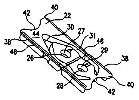
for use in the disclosed systems and methods. Figure 5 discloses an embodiment
of a diagnostic system 20 according to the present invention that may be
utilized
5 for many types of diagnostic testing. Such diagnostic tests utilize a
biological test
specimen such as, for example, tissue biopsy, blood or saliva. The diagnostic
system 20 may include a container 22 and a mechanism by which a user may
manipulate a sample of tissue, such as, for example, the specimen-handling
tool
24 that is shown in Figures 5, 10 and 14. As depicted in Figure 19, the
diagnostic
0 system 20 may further include an overlying member 23.
As shown in Figures 5-7, 9, and 16, the container 22 may include a first well
26 and a second well 28. The wells 26 and 28 may be defined, at least in part,
by
the walls 27 and 29, respectively. The wells 26 and 28 may be formed to have a
variety of different depths and cross-sectional shapes, some variations of
which
5 are shown in Figures 5, 16-18 and 20. The wells 26 and 28 of the container
22
may be variously formed, and may have similar configurations or dissimilar
configurations. As shown in Figures 7 and 17, the wells 26 and/or 28 may be
generally frustoconical in shape, although the wells 26 and/or 28 may be
cylindrical
or otherwise shaped. The wells 26 and/or 28 may be formed so that, when viewed
0 from the top of the container 22, the wells 26 and/or 28 have a non-circular
shape,
such as an elliptical, square, rectangular, D-shaped or any other shape.
One or more projecting members, such as the projecting member 34 that is
shown in Figures 16-18, may be disposed within one or both of the wells 26 and
CA 02462649 2004-04-O1
WO 03/034061 PCT/US02/29814
28. At least a portion of the projecting member 34 may be disposed outside of
the
interior of the wells 26 and/or 28. The projecting member 34 may be integrally
formed with the walls 27 and 29, or may be attached to the walls 27 and/or 29.
Such projecting members 34 may be configured to assist removal of the specimen
such as, for example, a biopsy specimen, from the specimen-handling tool 24.
These projecting members 34 may be configured to assist the user in accurately
positioning a specimen within the well 26 or 28.
The wells 26 and 28 may also include a step such as the step 32 that is
depicted in Figure 20.
0 The container 22 may have many different overall exterior shapes, such as,
for example, the generally rectangular shape as shown in Figures 5, 6 and 9.
The
container 22 may be alternately shaped, such as, for example, square, oblong,
triangular, and the like. The container 22 may, as shown in Figures 5-7,
include
two elongated sides 38, two ends 40 and a surf ace 44. The ends 40 may be
5 configured to be easily grasped by a user and one, none or both of the ends
40
may include an arcuate portion 42 as shown in Figures 5 - 9.
As shown in Figures 5, 6, 8 and 9, the container 22 may include a surface
44. The first and/or second wells 26 and 28, respectively, may be configured
to
extend downwardly from the surface 44. As shown in Figures 5 and 6, the
0 container 22 may also include a cavity 30. In a similar manner, the cavity
30 may
be configured to extend downwardly from the surface 44, as shown in Figures 5,
6
and 9. As shown in Figures 16-18, one or both of the wells 26 and 28 and/or
the
cavity 30 may be formed so as to extend upwardly from at least a portion of
the
surface 44.
5 A mechanism by which a user may manipulate a sample of tissue, such as,
for example, the specimen handling tool 24 such as that shown in Figures 5 and
10-15, may also be included in particular embodiments of the diagnostic system
20
of the present invention. The specimen-handling tool 24 may be disposed within
the cavity 30.
0 The cavity 30 may, as shown in Figures 5-7, be configured so that it is
disposed about at least a portion of one of the first and/or second wells_26
and 28,
respectively. The container 22 may also be configured so that a specimen
handling tool 24 may be otherwise retained in the container 22 so that it is
16
CA 02462649 2004-04-O1
WO 03/034061 PCT/US02/29814
disposed about at least a portion of one of the first and/or second wells 26
and 28,
respectively. The specimen handling tool can be shaped like a pair of tweezers
as
shown or in the shape of a single member pointed instrument that can pick up a
specimen by lancing the sample. As shown in Figures 16 and 17, the container
22
may be configured so that the specimen-handling tool 24 is secured in a
particular
position by one or more ribs 84. The specimen-handling tool 24 may be
removably
attached to the container 22 by one or more locking arms, breakaway tabs,
adhesive, or the like.
One or more rails 46 may be included in selected embodiments of the
0 present invention and may be disposed on the container 22 so that the rails
extend
upwardly along at least a portion of the surface 44. One or more rails 46 may
also
be configured to extend outwardly from the container 22. At least one gap 48
may
be formed in one of the rails 46 that extend along a portion of the container
22.
As shown in Figure 7, one or more supports 50 may be provided which
5 extend downwardly from the surface 44. As seen in Figure 7, the supports 50
may
be attached to the wall (or walls) 31 that form at least a portion of the
cavity 30.
The supports 50 may extend outwardly from the wall 31 to permit the container
22
to rest in a stable position on a horizontal or other surface. The rails 46
and the
supports 50 may be configured to enable the container 22 to be automatically
0 processed through a variety of equipment.
If desired, the surface 44 may be configured so that various indicia, such as
letters, numbers, symbols and other characters, may be placed onto or formed
into
the surface 44. For example, and as shown in Figure 6, each well 26 and/or 28
may be given a particular designation, such as A or B, and that designation
may
5 be printed upon the surface 44.
The container 22 may be formed from a variety of materials, including, for
example, polycarbonate, polystyrene, polypropylene, polyethylene,
polyvinylchloride, or any other type of polyolefin.
Particular embodiments of the specimen-handling tool 24 are shown in
0 Figures 10 - 15 and 21. The specimen-handling tool 24 may include, as shown
in
Figures 10-13, a pair of cooperating arms 54 and 55. Each arm 54 and 55 may
include a tip portion 56 and 57, respectively. The arms 54 and 55 may each
also
include a rear portion 58 and 59, respectively. The arms 54 and 55 may be
joined
17
CA 02462649 2004-04-O1
WO 03/034061 PCT/US02/29814
to each other at their rear portions 58 and 59, respectively, forming a joined
end
60. The joined end 60 may be configured to assist the user in accomplishing
particular tasks, such as, for example, manipulating a specimen, removing a
plug
86 from one of the first and/or second wells 26 and 28, respectively, as well
as
other tasks. The outermost portion of the joined end 60 may be variously
configured, and may be formed as a narrow projection, such as that shown in
Figure 14.
As seen in Figures 12 and 13, each arm 54 and 55 may also include a
rearward arcuate portion 62 and 63, respectively, and a forward arcuate
portion 66
0 and 67, respectively. Disposed between each rearward arcuate portion 62 and
63
and its corresponding forward arcuate portion 66 and 67, respectively, is an
intermediate arcuate portion 64 and 65, respectively. The arcuate portions 62-
64-
66 and 63-65-67 of each arm 54 and 55, respectively, may be configured so that
the area disposed between the arms 54 and 55 is approximately hourglass in
5 shape. In such an embodiment, the rearward arcuate portions 62 and 63 and
forward arcuate portions 66 and 67 curve outwardly, and the intermediate
arcuate
portions 64 and 65 curve inwardly.
The intermediate arcuate portions 64 and 65 may be formed so that a user
may more easily grip these portions. As shown in Figure 10, one or more ribs
52
0 may be positioned on the outer surface of the intermediate arcuate portions
64 and
65. Alternately, a portion of the arms 54 and/or 55 may have a roughened
texture
to enable a user to more effectively grasp and manipulate the specimen-
handling
tool 24, such as is shown in Figure 14 at 51.
The arms 54 and/or 55 may include fewer or more arcuate portions than the
.5 three arcuate portions described above, such as the specimen-handling tool
shown in Figure 15. The arcuate portions of the arms 54 and/or 55 may have a
more or less pronounced arcuate shape than what is depicted in Figure 10. For
example and as shown in Figures 14 - 16 and 21, other configurations of the
arms
54 and 55 may be used in the specimen-handling tool 24.
~0 The tip portions 56 and 57 may be variously formed to enable a user to
manipulate a specimen. The tip portions 56 and 57 may be formed to include a
surface such as the surfaces 70. The surfaces 70 may be variously shaped and,
in particular, one or both of the surfaces 70 may be curved (as shown in
Figure 14)
18
CA 02462649 2004-04-O1
WO 03/034061 PCT/US02/29814
or flat (as shown in Figure 10). The surfaces 70 may be rough or smooth. Also,
structures such as the ridges 78 that are depicted in Figure 15 may also be
positioned on one or more of the surfaces 70. The surfaces 70 may be disposed
so that they are at least somewhat facing each other, thereby enabling a user
to
grasp a specimen and hold it between the surfaces 70. As shown in Figure 14,
the
tip portions 56 and/or 57 may curve outwardly, and may, in some embodiments
such as is shown in Figure 15, end in a relatively sharp edge 74. One or both
of
the tip portions 56 and 57 may include a point, such as the point 80 shown in
Figure 14 or a fork 82, also shown in Figure 14, or any number of other
0 configurations.
The specimen-handling tool may be formed from a variety of materials,
including, for example, polycarbonate, polystyrene, polypropylene,
polyethylene,
polyvinylchloride, or any other type of polyolefin.
Referring now to Figures 19 and 20, an overlying member 23 may be
5 disposed over at least a portion of the surface 44 of the container 22. At
least a
portion of the cavity 30 may be formed by the wall 31. The overlying member 23
may take the form of an adhesive-backed label that adheres to at least a
portion of
the surface 44. The overlying member 23 may overly any combination of the
first
well 26, the second well 28 and the cavity 30.
0 The overlying member 23 may also be used to seal the first and second
wells 26 and 28, respectively. In some embodiments, the overlying member may
be used to regulate the rate of water vapor transmission to and from the wells
26
and 28 of the container 22. The overlying member 23 may also be configured so
that, if the overlying member 23 is removed prematurely or inadvertently, it
may be
5 easily reapplied to the container 22 so that the wells 26 and 28 may be
resealed.
The overlying member 23 may also be used to retain the specimen-handling
tool 24 within the cavity 30. The overlying member 23 may also be configured
only
to retain the specimen-handling tool 24 within the cavity 30. In some
embodiments, the overlying member 23 may be adhered to at least a portion of
the
0 specimen-handling tool 24 so that, when the overlying member 23 is removed
form
the container 22, the specimen-handling tool 24 is also removed from the
container
22. Although this may be accomplished in many different ways, the intermediate
arcuate portions 64 and 65 may, when the specimen-handling tool 24 is
positioned
19
CA 02462649 2004-04-O1
WO 03/034061 PCT/US02/29814
within the cavity 30, be level with or rise slightly above the surface 44 so
as to
contact and be adhered to the overlying member 23.
As shown in Figure 20, a plug 87 may also be used to at least partially seal
each well 26 and 28. In such a configuration, the overlying member 23 does not
need to seal the well that contains the plug 87, but may merely be positioned
above the well 26 and/or 28. The plug 87 may be formed from a variety of
materials, including, for example, rubber, wax, silicone, or any of a variety
of
plastics. In some embodiments, a film cover 86, shown in Figure 18, may also
be
applied to a portion of the container 22, such as, for example, the well 28.
0 In some embodiments, the overlying member 23 may be adhered or
otherwise connected to one or more of the plugs 87 so that, when the overlying
member 23 is separated from the container 22, one or more of the plugs 87 may
also be removed. The plug 87 may also be removed with the specimen-handling
tool.
5 Example
The following example was performed in order to demonstrate the stability
of a urease testing device made in accordance with the present invention.
A test slide according to the present invention was prepared
containing the urea composition and the indicator gel composition described
0 above. The indicator gel composition, however, did not contain the methyl
paraben bactericide or the citric acid pH adjuster.
Specifically, the gel composition contained the following:
In redient Amount
Extra Pure Gradear1.4941
A
Phenol Red 0.0110
Distilled Water~ 100.OOmL~
'5 The shelf life of the above prepared slide was then compared with the shelf
life of a commercial product marketed under the name CLO-TEST by Ballard
Medical/Kimberly Clark of Draper, Utah. The CLO-TEST product includes a
urease indicator composition which contains a mixture of urea and an indicator
in a
gel as described in U.S. Patent No. 4,748,113.
CA 02462649 2004-04-O1
WO 03/034061 PCT/US02/29814
Three test slides made according to the present invention were compared
with three samples of the CLO-TEST product. A standardized CLO-TEST Color
Chart developed prior to the experiment was used to assign numerical scores to
the color of the samples during the experiment.
The slides were affixed to a polystyrene box introduced into a chamber set
at 37 °C, 100% relative humidity, and 10% carbon dioxide. Photographs
were
taken every 24 hours for a period of 45 days, which were then assessed and
given
a score using the CLO-TEST Color Chart. Using color readings with scores of
equal to or greater than 4 as unusable, the CLO-TEST samples were deemed
0 unusable on day 4, while the test slides of the present invention were still
viable on
day 45.
The shelf life of the test slide of the present invention was also tested with
an artificial biopsy by means of a tissue sample containing deliberately
introduced
urease. The artificial biopsy sample was placed in the first well containing
the
5 powdered urea. The sample was coated with urea, and then placed in the
second
well containing the indicator gel composition. Observations of the color
change of
the gel revealed it was still viable for the detection of ammonia after 39
days, when
the gel was checked.
It should be noted that any given range presented herein is intended to
0 include any and all lesser included ranges. For example, a range of from 45-
90
would also include 50-90; 45-80; 46-89 and the like. Thus, the range of 95% to
99.999% also includes, for example, the ranges of 96% to 99.1 %, 96.3% to
99.7%,
and 99.91 to 99.999%.
21