Language selection

Search

Patent 2463201 Summary

Third-party information liability

Some of the information on this Web page has been provided by external sources. The Government of Canada is not responsible for the accuracy, reliability or currency of the information supplied by external sources. Users wishing to rely upon this information should consult directly with the source of the information. Content provided by external sources is not subject to official languages, privacy and accessibility requirements.

Claims and Abstract availability

Any discrepancies in the text and image of the Claims and Abstract are due to differing posting times. Text of the Claims and Abstract are posted:

  • At the time the application is open to public inspection;
  • At the time of issue of the patent (grant).
(12) Patent: (11) CA 2463201
(54) English Title: BREATHALYZER WITH AN IMPROVED MOUTHPIECE
(54) French Title: IVRESSOMETRE A EMBOUT AMELIORE
Status: Term Expired - Post Grant Beyond Limit
Bibliographic Data
(51) International Patent Classification (IPC):
  • A61B 5/097 (2006.01)
  • G01N 1/22 (2006.01)
  • G01N 1/24 (2006.01)
  • G01N 33/497 (2006.01)
(72) Inventors :
  • STOCK, BURKHARD (Germany)
  • REKOW, JENS (Germany)
  • CHRZAN, RIGOBERT (Germany)
(73) Owners :
  • DRAEGER SAFETY AG & CO. KGAA
(71) Applicants :
  • DRAEGER SAFETY AG & CO. KGAA (Germany)
(74) Agent: SMART & BIGGAR LP
(74) Associate agent:
(45) Issued: 2009-12-22
(22) Filed Date: 2004-04-05
(41) Open to Public Inspection: 2004-10-10
Examination requested: 2004-04-05
Availability of licence: N/A
Dedicated to the Public: N/A
(25) Language of filing: English

Patent Cooperation Treaty (PCT): No

(30) Application Priority Data:
Application No. Country/Territory Date
103 16 333.6 (Germany) 2003-04-10

Abstracts

English Abstract

The present invention describes a breathalyzer (7) that is unproved with respect to handling, especially of the replaceable mouthpiece (1), direct physical contact between the test subject and the breathalyzer being precluded for all practical purposes. The breathalyzer (7) is characterized in that the mouthpiece (1) is of a trapezoidal cross- section that is complementary to a corresponding negative shape within the holder (6) of the breathalyzer (7) so as to ensure a flush fit for the mouthpiece (1).


French Abstract

La présente invention fournit la description d'un ivressomètre (7) qui est amélioré en ce qui a trait à la manutention, tout particulièrement celle de l'embout amovible (1), offrant un contact physique direct pratiquement impossible entre le sujet soumis au test et l'appareil. L'ivressomètre (7) a pour caractéristique particulière que son embout (1) est de section trapézoïdale complémentaire de la forme négative correspondante à l'intérieur du support (6) de l'appareil (7), de manière à garantir un montage affleurant de l'embout (1).

Claims

Note: Claims are shown in the official language in which they were submitted.

CLAIMS:
1. Breathalyzer with a mouthpiece that is configured
as a pressure tube, with a bore for sampling a breath for an
alcohol sensor, wherein the mouthpiece is of a trapezoidal
cross-section that is complementary to a corresponding
negative shape within a holder of the breathalyzer so as to
ensure a flush fit for the mouthpiece, and the mouthpiece
further having a stop that encircles the mouthpiece on the
outside, in the peripheral direction of the cross-section,
at least in sections, and which fixes the position of the
mouthpiece in the longitudinal direction relative to the
holder so that an induction channel for sampling the breath
extends through the bore.
2. Breathalyzer as defined in claim 1, wherein the
trapezoidal cross-section of the mouthpiece is equal sided;
and in that the bore for sampling the breath is located in
the shorter of the two parallel sides of the cross section
of the mouthpiece.
3. Breathalyzer as defined in claim 1 or claim 2,
wherein the mouthpiece is accommodated in the holder
parallel to one of the two short end surfaces of the
breathalyzer, the breathalyzer being rectangular
parallelepiped shaped.
4. Breathalyzer as defined in any one of claims 1
to 3, wherein the mouthpiece has a positioning pin which is
arranged outside the holder when the mouthpiece is
accommodated in the holder.
5. Breathalyzer as defined in claim 1 or claim 4,
wherein the alcohol sensor is an electro-chemical sensor
that is connected so as to enable a flow with the induction
channel; such that the breath is sampled by the alcohol
6

sensor by means of a sampling stroke of a pump incorporated
after the alcohol sensor.
6. Breathalyzer as defined in any one of claims 2 to
5, wherein the holder and the mouthpiece are configured
symmetrically in relation to the breathalyzer, so that the
mouthpiece can be accommodated in two different positions in
the holder that subtend an angle of 180 degrees without a
preferred direction.
7

Description

Note: Descriptions are shown in the official language in which they were submitted.


CA 02463201 2007-10-22
2654~-11-7
Breathalyzer With an Improved Mouthpiece
The present invention relates to a breathalyzer.
A breathalyzer of this type is described in DE 195 45 794 C2, wherein within
the mouth
piece the stream of breath is divided into a main gas stream that flows
directly to the
environment and a test gas stream. The test gas stream passes through the
device's
sampling system and because of the structural configuration of the device is
adjusted
relative to the volumetric flow to a value that corresponds to the value
obtained fcom
lmown calibrating devices, so that it is possible to calibrate the sampling
system under
actual flow conditions. One disadvantage of this known breathalyzer is
deficient
hygiene and condensation of the stream of gas within the breathalyzer when the
divided
stream of test gas flows directly through the sampling system.
Another breathalyzer of this kind is described in EP 0 153 883 A2; using this
known
device, it is particularly difficult to install the mouthpiece that is of a
circular cross
section on the breathalyzer.
The present invention seeks to resolve the problem that results from the fact
that for
reasons of hygiene the mouthpiece must be replaced for each individual tested.
This
procedure should be as simple and as rapid as possible, since during
enforcement
operations many individuals have to be tested with a breathalyzer in a very
short period
of time, in particular at night, when visibility is very poor. The mouthpiece
must be
securely attached to the breathalyzer during the testing procedure in order
that it does not
become loose during testing. In addition, for reasons of hygiene it must be
ensured that
1

CA 02463201 2008-10-03
2=6541-117
the breath that is exhaled is routed only into the
mouthpiece and does not come into contact with the interior
of the breathalyzer. When providing a breath sample, the
individual being tested should only come into direct contact
with the replaceable mouthpiece; the subject's lips should
not come into contact with the breathalyzer itself.
Thus, it is the objective of the present invention
to describe a breathalyzer that has been significantly
improved with respect to handling, in particular with
respect to manipulating the replaceable mouthpiece. At the
same time, the present invention should for all practical
purposes preclude any direct physical contact between the
test subject and/or the exhaled breath sample and the
breathalyzer itself.
The present invention makes it easier to
manipulate the breathalyzer with respect to changing and
installing the replaceable mouthpiece in the breathalyzer,
which can be attributed in particular to the trapezoidal
cross section of the mouthpiece, with the matching shape of
the complementary holder on the breathalyzer.
In one broad aspect, there is provided
breathalyzer with a mouthpiece that is configured as a
pressure tube, with a bore for sampling a breath for an
alcohol sensor, wherein the mouthpiece is of a trapezoidal
cross-section that is complementary to a corresponding
negative shape within a holder of the breathalyzer so as to
ensure a flush fit for the mouthpiece, and the mouthpiece
further having a stop that encircles the mouthpiece on the
outside, in the peripheral direction of the cross-section,
at least in sections, and which fixes the position of the
mouthpiece in the longitudinal direction relative to the
holder so that an induction channel for sampling the breath
2

CA 02463201 2008-10-03
Z6541-117
extends through the bore.
One particularly preferred configuration of the
present invention is characterized in that the trapezoidal
cross-section of the mouthpiece has two sides that are of
equal length, and the bore in the mouthpiece for taking the
breath sample is located in a shorter of the two parallel
sides of the mouthpiece cross section. Another preferred
embodiment is characterized in that the mouthpiece
incorporates a stop that encircles it on the outside, in the
peripheral direction, at least in part, and this establishes
the correct position of the
2a

CA 02463201 2004-04-05
mouthpiece in the longitudinal direction relative to the holder, so that the
breathalyzer
induction channel through which the breath sample is taken passes exactly
through the
bore in the mouthpiece.
The present invention will be described in greater detail below on the basis
of the
drawings appended hereto. These drawings show the following:
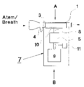
Figure 1: A diagrammatic representation of a breathalyzer;
Figure 2: a vertical cross-section on the line A-B shown in Figure 1.
Figure 1 shows a breathalyzer 7. Breathalyzersof this pipe are marketed, in
particular,
under the brand name Alcotest . The replaceable mouthpiece 1 is inserted into
the
holder 6 and is made, for example, from a plastic such as polyethylene. The
mouthpiece
1 incorporates a bore 10 through which the induction channel 8 extends into
the stream
of breath that is blown into the breathalyzer from the left-hand side in
Figure 1. The
pump 9 is so controlled that it conveys a breath sample from the stream of
breath into the
breathalyzer and thus into the alcohol sensor 5 by means of a sampling stroke,
once the
subject has blown a sufficient amount of breath through of the mouthpiece 1.
The
injection opening in the mouthpiece 1 is expanded in a circular shape in order
to permit a
good fit between the subject's lips. For the remainder, the mouthpiece I is of
a
trapezoidal cross-section (Figure 2) that is complementary to a corresponding
negative
shape of the holder 6 of the breathalyzer. It is preferred that the
trapezoidal cross-
section of the mouthpiece 1 have two equal sides and the bore 10 for taking
the breath
sample is located in a shorter of the two parallel sides of this cross-
section.
3

CA 02463201 2004-04-05
At the outlet end of the mouthpiece 1, which is the right-hand end of said
mouthpiece in
Figure 1, there is an outlet opening 2 with a diameter of approximately 4-5
mm.
Because of this, the stream of breath courses a back pressure within the
mouthpiece 1,
and this is detected by a pressure sensor 11. The pressure that is measured
corresponds
to a specific volumetric flow of breath, from which the volume of breath that
has
provided can be determined by time integration.
At least in the area of holder 6, the mouthpiece 1 is of a cross-section as
has been
described, the upper parallel side the holder 6 being approximately 9 mm long
and the
lower parallel side being approximately 4 mm long, the height of the trapezium
amounting to approximately 10 mm. The holder 6 is formed as a negative shape
to the
shape of the mouthpiece 1. The mouthpiece can be guided reliably on to the
three
complementary side surfaces and is securely seated in the liolder 6 thereby.
In addition,
the trapezoidal cross sectional shape of the mouthpiece 1 simplifies
installation in the
holder 6, so that the induction channel 8 extends as desired through the bore
10. The
orientation of the mouthpiece 1 relative to the breathalyzer is thus clearly
defined in
every instance. Furthermore, an external stop 3 is provided especially to
ensure the
correct lateral position of the mouthpiece 1 within the holder 6; this stop
encircles the
cross section of the mouthpiece 1, at least in sections, in the peripheral
direction, so that
the mouthpiece 1 will only be joined to the holder 6 to form a perfect match
when the
induction channel 8 extends through the bore 10. The slot 3 thus fixes the
correct lateral
position of the mouthpiece 1 relative to the holder 6. The optionally
available
positioning pin 4 serves as an aid for correctly aligning the mouthpiece 1 for
installation
in the holder 6, particularly if the mouthpiece 1 is still packaged, for
example, in foil
4

CA 02463201 2004-04-05
wrap. The positioning pin 4 is particularly helpful when tests are being
carried out in
poor light, and because, for reasons of hygiene, the mouthpiece 1 must still
be partially
packaged when the operator installs it on the holder 6. In addition, the
positioning pin 4
serves as a stand-off holder for the test subject, so that the test subject's
lips to not come
into contact with the breathalyzer itself.
According to a preferred embodiment, the mouthpiece 1 and the holder 6 are
configured
so as to be symmetrical relative to the breathalyzer 7, so that the mouthpiece
1 can be
installed in the holder 6 in two different positions that differ from one
another by 180 ,
thereby permitting improved manipulation of the mouthpiece 1.
5

Representative Drawing
A single figure which represents the drawing illustrating the invention.
Administrative Status

2024-08-01:As part of the Next Generation Patents (NGP) transition, the Canadian Patents Database (CPD) now contains a more detailed Event History, which replicates the Event Log of our new back-office solution.

Please note that "Inactive:" events refers to events no longer in use in our new back-office solution.

For a clearer understanding of the status of the application/patent presented on this page, the site Disclaimer , as well as the definitions for Patent , Event History , Maintenance Fee  and Payment History  should be consulted.

Event History

Description Date
Inactive: Expired (new Act pat) 2024-04-05
Common Representative Appointed 2019-10-30
Change of Address or Method of Correspondence Request Received 2018-03-28
Grant by Issuance 2009-12-22
Inactive: Cover page published 2009-12-21
Pre-grant 2009-09-30
Inactive: Final fee received 2009-09-30
Notice of Allowance is Issued 2009-08-31
Letter Sent 2009-08-31
Notice of Allowance is Issued 2009-08-31
Inactive: Approved for allowance (AFA) 2009-08-21
Amendment Received - Voluntary Amendment 2008-10-03
Inactive: S.30(2) Rules - Examiner requisition 2008-08-25
Amendment Received - Voluntary Amendment 2007-10-22
Inactive: S.30(2) Rules - Examiner requisition 2007-07-11
Inactive: S.29 Rules - Examiner requisition 2007-07-11
Inactive: IPC from MCD 2006-03-12
Inactive: Cover page published 2004-10-10
Application Published (Open to Public Inspection) 2004-10-10
Inactive: IPC assigned 2004-07-16
Inactive: First IPC assigned 2004-07-16
Letter Sent 2004-06-22
Inactive: Single transfer 2004-06-01
Inactive: Courtesy letter - Evidence 2004-05-18
Filing Requirements Determined Compliant 2004-05-14
Inactive: Filing certificate - RFE (English) 2004-05-14
Letter Sent 2004-05-10
Application Received - Regular National 2004-05-10
Request for Examination Requirements Determined Compliant 2004-04-05
All Requirements for Examination Determined Compliant 2004-04-05

Abandonment History

There is no abandonment history.

Maintenance Fee

The last payment was received on 2009-03-06

Note : If the full payment has not been received on or before the date indicated, a further fee may be required which may be one of the following

  • the reinstatement fee;
  • the late payment fee; or
  • additional fee to reverse deemed expiry.

Please refer to the CIPO Patent Fees web page to see all current fee amounts.

Owners on Record

Note: Records showing the ownership history in alphabetical order.

Current Owners on Record
DRAEGER SAFETY AG & CO. KGAA
Past Owners on Record
BURKHARD STOCK
JENS REKOW
RIGOBERT CHRZAN
Past Owners that do not appear in the "Owners on Record" listing will appear in other documentation within the application.
Documents

To view selected files, please enter reCAPTCHA code :


To view images, click a link in the Document Description column. To download the documents, select one or more checkboxes in the first column and then click the "Download Selected in PDF format (Zip Archive)" or the "Download Selected as Single PDF" button.

List of published and non-published patent-specific documents on the CPD .

If you have any difficulty accessing content, you can call the Client Service Centre at 1-866-997-1936 or send them an e-mail at CIPO Client Service Centre.


Document
Description 
Date
(yyyy-mm-dd) 
Number of pages   Size of Image (KB) 
Abstract 2004-04-05 1 18
Drawings 2004-04-05 1 20
Description 2004-04-05 5 218
Claims 2004-04-05 2 65
Representative drawing 2004-08-26 1 6
Cover Page 2004-09-27 1 33
Claims 2007-10-22 2 52
Description 2007-10-22 6 223
Claims 2008-10-03 2 57
Description 2008-10-03 6 231
Cover Page 2009-12-01 1 34
Acknowledgement of Request for Examination 2004-05-10 1 176
Courtesy - Certificate of registration (related document(s)) 2004-06-22 1 106
Filing Certificate (English) 2004-05-14 1 159
Reminder of maintenance fee due 2005-12-06 1 110
Commissioner's Notice - Application Found Allowable 2009-08-31 1 163
Correspondence 2004-05-14 1 26
Correspondence 2009-09-30 1 38