Language selection

Search

Patent 2463334 Summary

Third-party information liability

Some of the information on this Web page has been provided by external sources. The Government of Canada is not responsible for the accuracy, reliability or currency of the information supplied by external sources. Users wishing to rely upon this information should consult directly with the source of the information. Content provided by external sources is not subject to official languages, privacy and accessibility requirements.

Claims and Abstract availability

Any discrepancies in the text and image of the Claims and Abstract are due to differing posting times. Text of the Claims and Abstract are posted:

  • At the time the application is open to public inspection;
  • At the time of issue of the patent (grant).
(12) Patent: (11) CA 2463334
(54) English Title: LIFT ASSIST MECHANISM FOR LIFTING LARGE ENCLOSURES
(54) French Title: MECANISME FACILITANT LE LEVAGE DE GROSSES ENCEINTES
Status: Term Expired - Post Grant Beyond Limit
Bibliographic Data
(51) International Patent Classification (IPC):
  • E05F 7/06 (2006.01)
  • E02D 29/14 (2006.01)
  • E05F 1/10 (2006.01)
  • E05F 3/22 (2006.01)
  • E05F 5/00 (2017.01)
(72) Inventors :
  • MCCULLOUGH, ANDREW C. (United States of America)
(73) Owners :
  • SMITH & LOVELESS, INC.
(71) Applicants :
  • SMITH & LOVELESS, INC. (United States of America)
(74) Agent: FINLAYSON & SINGLEHURST
(74) Associate agent:
(45) Issued: 2009-12-15
(22) Filed Date: 2004-04-06
(41) Open to Public Inspection: 2004-11-09
Examination requested: 2009-04-03
Availability of licence: N/A
Dedicated to the Public: N/A
(25) Language of filing: English

Patent Cooperation Treaty (PCT): No

(30) Application Priority Data:
Application No. Country/Territory Date
10/434,591 (United States of America) 2003-05-09

Abstracts

English Abstract

A lift assist mechanism for lifting a large enclosure that is pivotally attached to a body member, between a closed position, an intermediate position, and an open position. The lift assist mechanism includes a swing arm member and an expansible strut member. The swing arm member is pivotally attached to the body member at a first end and to a first end of the strut member at the second end. The second end of strut member is pivotally attached to the enclosure member. The pivot point between the swing arm member and the strut member pushes against a base plate associated with the body member when the enclosure member is in its closed and intermediate positions.


French Abstract

Mécanisme facilitant le levage permettant de soulever une grande enceinte qui est fixée de façon pivotante à un élément de corps, entre une position fermée, une position intermédiaire et une position ouverte. Le mécanisme facilitant le levage comprend un élément de bras oscillant et un élément d'entretoise expansible. Le bras oscillant est fixé de manière pivotante à l'élément de corps à une première extrémité et à une première extrémité de l'élément d'entretoise au niveau de la seconde extrémité. La seconde extrémité de l'élément d'entretoise est fixée de manière pivotante à l'élément d'enceinte. Le point de pivotement entre le bras de pivotement et l'élément d'entretoise bute contre une plaque de base associée à l'élément de corps lorsque ladite enceinte est en position fermée et intermédiaire.

Claims

Note: Claims are shown in the official language in which they were submitted.

-6-
What is claimed is:
1. In combination, a lift assist mechanism for assisting in the pivotal
movement and lifting of an enclosure member with respect to a body member
between a closed position, an intermediate position, and an open position,
comprising:
a body member, said body member having base plate associated therewith;
an upstanding enclosure member pivotally attached along at least one edge
thereof to said body member so as to permit said enclosure member to move
between a closed position, an intermediate position, and an open position;
a swing arm member having a first end portion and a second end portion,
said first end portion of said swing arm being pivotally connected to said
body
member;
an expansible strut member having a first end portion and a second end
portion, said first end portion of said strut member being pivotally connected
to said
second end portion of said swing arm member and said second end portion of
said
strut being pivotally connected to said enclosure member, said strut having a
contracted condition when the enclosure member is in its closed position and
an
extended condition when said enclosure is in its intermediate and open
positions;
whereby when said closure member is in its closed and intermediate positions
said second end of said swing arm member and said first end of said strut
member
are in contact with said base plate, and when said closure member is in its
open
position said second end of said swing arm member and said first end of said
strut
member are spaced from said base plate member so that said strut member is
neither assisting nor detracting from the opening or closing of the enclosure
member.
2. The combination as set forth in claim 1, wherein:
said expandable strut member is a gas shock member.
3. The combination as set forth in claim 1, wherein:
said first end portion of said swing arm member is pivotally attached to a
first bracket
member attached to said body member.

-7-
4. The combination as set forth in claim 1, wherein:
said second end portion of said strut is pivotally attached to a second
bracket
member attached to said enclosure member.
5. The combination as set forth in claim 3, wherein:
said first bracket member has a plurality of spaced apart openings formed
therein so that the location of the first end portion swing arm member
relative to the
body member may be adjusted.
6. The combination as set forth in claim 4, wherein:
said second bracket member has a plurality of spaced apart openings formed
therein so that the location of the second end portion of the strut member
relative to
the enclosure member may be adjusted.
7. The combination as set forth in claim 1, wherein:
a bumper member is provided at the pivot point between the second end
portion of the swing member and the first end portion of the strut
member to contact the base plate when the enclosure is in its closed and
intermediate positions.

Description

Note: Descriptions are shown in the official language in which they were submitted.


CA 02463334 2004-04-06
-1-
LIFT ASS6ST MECHANISM FOR LIFTING LARGE ENCLOSURES
Field of the Invention
This invention is generally directed to a device or mechanism for assisting in
the lifting of large enclosures. More specifically, this invention is directed
to a device
or mechanism for assisting in the lifting of a tall hood member that provides
above-ground entry into the mechanical section of a buried pumping station.
Background of the Invention
it has hereto been common practice to use gas shocks to assist in the
opening or lifting of large or tall enclosures. This was typically
accomplished using
one of two methods. In the first method, the gas shocks were under-sized to
allow
the user to still be able to close the enclosure, while still providing a
degree of
assistance. fn the second method, the travel of the enclosure is limited to
forty five
degrees. This permits the gas shocks to be sized correctly, but prevents the
enclosure from being fully opened unless the gas shocks .are uninstalled. Both
of
these options require the use of an end restraint to prevent the hood from
over-extending the gas shock and thereby shortening its life.
The design of assist mechanisms that utilize gas shocks for enclosures that
are tall presents unique problems. While the gas shocks will successfully lift
the
enclosure, in the full open position (approximately ninety degrees from
horizontal),
the center of gravity is located behind the hinge. As a consequence thereof,
in order
to close the enclosure, the operator is required to not only overcome the
weight of
the enclosure, but also the strength of the gas shocks. This in turn limits
the strength
of the shock that can be used, as a stronger shock would ;severely hamper an
operator's ability to close the enclosure. Since the strength of the gas shock
is
limited, the amount of assistance that can be supplied in opening the
enclosure is
also limited.
The alternative is to limit the travel of the enclosure such that the gas
shocks
do not push the center of gravity of the enclosure past the hinge. In some
applications, this only allows for the enclosure to be opened about forty five
degrees
instead of ninety degrees. Some applications have allowed the gas shocks to be

CA 02463334 2004-04-06
-2-
removed as a part of operating the enclosure when it is necessary to open it
beyond
the travel of the gas shocks.
AdditionaPly, it has heretofore been necessary to take great care to prevent
the gas shocks from over-extending, such as the utilization of an end-stop. If
the gas
shocks are permitted to fully extend before the endstop is engaged, the weight
of the
enclosure will tend to over-extend the shocks and thereby greatly reduce their
useful
life.
Summary of the Invention
In accordance with the present invention, a left assist mechanism is provided
that decreases the work required by an operator to fully open an enclosure or
hoed
for entry into a mechanical section of a system, such as a wastewater or
sewage
pumping station.
The lift assist mechanism includes a swing arm member and an expandable
strut or gas shock member. The swing arm member has a first end portion
pivotally
attached to the body member and a second end portion pivotally attached to a
first
end portion of the strut member. The strut member has a second end portion
that is
pivotally attached to the enclosure member.
The body member has a base plate member associated therewith. The strut
member has a contracted condition when the enclosure rnember is in its closed
portion and an extended condition when the enclosure member is in its
intermediate
and fully open position. The pivot point between the swincg arm member and the
first
end of the enclosure member is pressed against the base plate when the
enclosure
member is in its closed and intermediate positions. The pivot point between
the
swing arm member and the first end of the enclosure member is lifted up from
the
base plate member when the enclosure member is in its open position.
Brief Description of the Drawings
These and other features of the invention will appear from the following
written description, and from the drawings, in which:
FIG. 1 is a schematic elevational view showing the lift mechanism in
accordance with the invention, with the enclosure member in its closed
position;
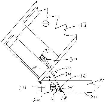
FIG. 2 is a similar view of FIG. 1, but showing the enclosure member in its
intermediate position;

CA 02463334 2004-04-06
-3-
FIG. 3 is a similar view to FIG. 1, but showing the enclosure member in its
fully open position; and
FIG. 4 is a schematic view showing the attachment of the swing arm member
to the bracket member.
Description of the Preferred Embodiment
Referring to FIGS. 1-3, a lift assist mechanism is constructed in accordance
with the present invention is indicated at 10. Lift assist mechanism 10 is
shown in
combination with an enclosure ar hood member 12 associated with the body
portion
14 that houses a mechanical system, such as a wastewater or sewage pumping
station. The present invention is particularly applicable for use in
connection with
heavy enclosure members that have a tall profile.
Lift assist mechanism 10 comprises a swing arm member 16, and an
expansible strut member or gas shock 18. It is contemplated that a !ift assist
mechanism 10 may be provided on each side of the enclosure member 12 to
IS facilitate opening and closing of the enclosure member. The enclosure
member 12
is pivotally hinged to the body portion 14 in any well-known manner. The body
portion 74 is provided with a base plate 20 extending therefrom.
Swing arm member 16 is a link arm member having a first end portion 22 and
a second end portion 24. The first end portion 22 is pivotally attached to.
the body
portion 14. The first end portion 22 is preferably pivotally attached to a
first bracket
member 26 suitably attached to the body portion 14. Bracket member 26 is
preferably provided with a plurality of spaced apart openings through which a
pivot
pin passing through the first end portion 22 may extend.
The expansible strut member 18 is preferably a conventional gas strut or
shock member having a cylinder portion 28 defining a first end 30 portion and
a rod
portion 34 defining a second end portion 36. The second end portion 36 of
strut
member 18 is pivotally attached to the second end portion 24 of swing arm
member
16. The first end portion 30 of strut member 18 is pivotally attached to a
side portion
of the enclosure member 12. The first end portion 30 is preferably pivotally
attached
to a second bracket member 32 suitably attached to the enclosure member 12.
Bracket member 32 is provided with a plurality of spaced apart openings
through

CA 02463334 2004-04-06
-4-
which a pivot pin passing the second end portion 30 of the strut member 18 may
extend.
For reasons that will hereinbelow become more apparent, the pivot point
between the swing arm member 16 and the strut member 18 is urged into contact
with the base plate 20 by the force of the gas strut and the weight of the
enclosure
when the enclosure is in its closed and intermediate positions. A suitable
bumper
member 38 is preferably provided at the pivot point between the swing arm
member
and the strut member.
Referring to FIG. 1, the enclosure member 12 is shown in its closed position
in covering relationship to the body portion 14. The gas strut 18 is in its
contracted
condition and the bumper member 38 is in contact with and pushing on the base
plate 20.
Referring to FIG. 2, when it is desired to gain access to the body portion 14,
the operator provides an upward lifting force to the enclosure member 12. in
so
doing, the strut member assists in the lifting of the enclosure member into an
intermediate or partially open position. In the intermediate position, the
strut member
is fully extended and supports the weight of the enclosure member. The bumper
38
is still pressed against the base plate 20 by the force of the strut member
and the
weight of the enclosure member.
Referring to FIG. 3, continued Lifting of the enclosure member 12 into its
fully
open position, causes the bumper member 38 to be lifted off the base plate due
to
the presence of the swing arm member 16. At this point, the strut member 18 is
neither assisting nor detracting from the opening or closing of the enclosure
member. The inclusion of the pivot point permits the strength of the strut
member to
be increased without adding to the difficulty associated with the dosing of
the
enclosure member. The operator does not have to overcome the adverse moment
generated by the strut member while moving the enclosure member from its fully
open position to its intermediate position.
Referring to FIG. 4, to increase the effectiveness of the strut member, and
hence its strength, the swing arm 16 may be moved to an opening in the bracket
member 26 furthest from the hinge between the enclosure member 12 and the body

CA 02463334 2004-04-06
-5-
portion 14. This extends the useful life of the strut member 18 as permits
adjustment
of the assist to the operator's taste.
The foregoing disclosure is the best mode devised by the inventor for
practicing this invention. It is apparent, however, that apparatus
incorporating
modifications and variations will be obvious to one skilled in the art.
Insomuch as the
foregoing disclosure is intended to enable one skilled in the pertinent art to
practice
the instant invention, it should not be construed to be limited thereby but
should be
construed to include such aforementioned obvious variations and be limited
only by
the spirit and scope of the following claims.

Representative Drawing
A single figure which represents the drawing illustrating the invention.
Administrative Status

2024-08-01:As part of the Next Generation Patents (NGP) transition, the Canadian Patents Database (CPD) now contains a more detailed Event History, which replicates the Event Log of our new back-office solution.

Please note that "Inactive:" events refers to events no longer in use in our new back-office solution.

For a clearer understanding of the status of the application/patent presented on this page, the site Disclaimer , as well as the definitions for Patent , Event History , Maintenance Fee  and Payment History  should be consulted.

Event History

Description Date
Inactive: Expired (new Act pat) 2024-04-08
Inactive: IPC assigned 2022-08-08
Common Representative Appointed 2019-10-30
Inactive: IPC expired 2017-01-01
Grant by Issuance 2009-12-15
Inactive: Cover page published 2009-12-14
Pre-grant 2009-09-25
Inactive: Final fee received 2009-09-25
Notice of Allowance is Issued 2009-07-13
Letter Sent 2009-07-13
Notice of Allowance is Issued 2009-07-13
Inactive: Approved for allowance (AFA) 2009-06-16
Advanced Examination Requested - PPH 2009-05-22
Advanced Examination Determined Compliant - PPH 2009-05-22
Letter Sent 2009-05-07
Request for Examination Received 2009-04-03
Request for Examination Requirements Determined Compliant 2009-04-03
All Requirements for Examination Determined Compliant 2009-04-03
Inactive: IPC from MCD 2006-03-12
Application Published (Open to Public Inspection) 2004-11-09
Inactive: Cover page published 2004-11-08
Inactive: First IPC assigned 2004-10-22
Inactive: IPC assigned 2004-10-22
Inactive: Filing certificate - No RFE (English) 2004-05-11
Filing Requirements Determined Compliant 2004-05-11
Letter Sent 2004-05-11
Application Received - Regular National 2004-05-11

Abandonment History

There is no abandonment history.

Maintenance Fee

The last payment was received on 2009-03-18

Note : If the full payment has not been received on or before the date indicated, a further fee may be required which may be one of the following

  • the reinstatement fee;
  • the late payment fee; or
  • additional fee to reverse deemed expiry.

Please refer to the CIPO Patent Fees web page to see all current fee amounts.

Owners on Record

Note: Records showing the ownership history in alphabetical order.

Current Owners on Record
SMITH & LOVELESS, INC.
Past Owners on Record
ANDREW C. MCCULLOUGH
Past Owners that do not appear in the "Owners on Record" listing will appear in other documentation within the application.
Documents

To view selected files, please enter reCAPTCHA code :


To view images, click a link in the Document Description column. To download the documents, select one or more checkboxes in the first column and then click the "Download Selected in PDF format (Zip Archive)" or the "Download Selected as Single PDF" button.

List of published and non-published patent-specific documents on the CPD .

If you have any difficulty accessing content, you can call the Client Service Centre at 1-866-997-1936 or send them an e-mail at CIPO Client Service Centre.


Document
Description 
Date
(yyyy-mm-dd) 
Number of pages   Size of Image (KB) 
Description 2004-04-06 5 252
Abstract 2004-04-06 1 21
Claims 2004-04-06 2 80
Drawings 2004-04-06 2 48
Representative drawing 2004-10-13 1 9
Cover Page 2004-10-25 1 38
Abstract 2009-05-22 1 18
Representative drawing 2009-11-20 1 11
Cover Page 2009-11-20 1 40
Courtesy - Certificate of registration (related document(s)) 2004-05-11 1 106
Filing Certificate (English) 2004-05-11 1 159
Reminder of maintenance fee due 2005-12-07 1 110
Reminder - Request for Examination 2008-12-09 1 117
Acknowledgement of Request for Examination 2009-05-07 1 175
Commissioner's Notice - Application Found Allowable 2009-07-13 1 161
Correspondence 2009-09-25 1 37