Language selection

Search

Patent 2463383 Summary

Third-party information liability

Some of the information on this Web page has been provided by external sources. The Government of Canada is not responsible for the accuracy, reliability or currency of the information supplied by external sources. Users wishing to rely upon this information should consult directly with the source of the information. Content provided by external sources is not subject to official languages, privacy and accessibility requirements.

Claims and Abstract availability

Any discrepancies in the text and image of the Claims and Abstract are due to differing posting times. Text of the Claims and Abstract are posted:

  • At the time the application is open to public inspection;
  • At the time of issue of the patent (grant).
(12) Patent Application: (11) CA 2463383
(54) English Title: POLLEN CLEANING METHOD AND DEVICE
(54) French Title: PROCEDE ET DISPOSITIF DE NETTOYAGE DU POLLEN
Status: Deemed Abandoned and Beyond the Period of Reinstatement - Pending Response to Notice of Disregarded Communication
Bibliographic Data
(51) International Patent Classification (IPC):
  • B01D 36/04 (2006.01)
  • B01D 36/00 (2006.01)
  • B01D 45/16 (2006.01)
(72) Inventors :
  • TOMEK, JIRI (Czechia)
(73) Owners :
  • JIRI TOMEK
(71) Applicants :
  • JIRI TOMEK (Czechia)
(74) Agent: NORTON ROSE FULBRIGHT CANADA LLP/S.E.N.C.R.L., S.R.L.
(74) Associate agent:
(45) Issued:
(86) PCT Filing Date: 2002-06-17
(87) Open to Public Inspection: 2003-05-22
Availability of licence: N/A
Dedicated to the Public: N/A
(25) Language of filing: English

Patent Cooperation Treaty (PCT): Yes
(86) PCT Filing Number: PCT/CZ2002/000035
(87) International Publication Number: WO 2003041840
(85) National Entry: 2004-04-08

(30) Application Priority Data:
Application No. Country/Territory Date
PV 3649-01 (Czechia) 2001-10-10

Abstracts

English Abstract


The basis of the pollen cleaning method is that the contaminated pollen (6) is
sucked by airflow carrying the pollen to the conical part (16) of the
separator (3) made of insulating material where pure pollen particles fall
through the separator onto the filter (2) while the impurities rotate in
electrostatic field generated by separator (3) friction. The device used for
implementation of this method consists of a suction unit (1) with a filter
(2). To the filter is led the separator outlet (3). In the area of the
greatest separator diameter, the outlet of the suction line of a variable
diameter is tangentially connected to the separator (3) incluidng a suction
part (5) for contaminated pollen (6) suction.


French Abstract

La base de ce procédé de nettoyage du pollen consiste à aspirer le pollen contaminé (6) à l'aide d'un écoulement d'air qui transporte le pollen vers la partie conique (16) du séparateur (3) constitué d'un matériau isolant, dans lequel les particules de pollen pur tombent à travers le séparateur sur le filtre (2) alors que les impuretés tournent dans un champ électrostatique généré par le frottement du séparateur (3). Le dispositif utilisé pour la mise en oeuvre de ce procédé comprend une unité d'aspiration (1) avec un filtre (2). L'orifice de sortie du séparateur (3) débouche sur le filtre. Dans la zone de plus grand diamètre du séparateur, l'orifice de sortie de la ligne d'aspiration d'un diamètre variable est relié tangentiellement au séparateur (3) qui comprend une partie d'aspiration (5) pour l'aspiration du pollen contaminé (6).

Claims

Note: Claims are shown in the official language in which they were submitted.

-4-
CLAIMS
1. The pollen cleaning method of mechanical impurities, dust and
microorganisms
comprising by that contaminated pollen (6) is sucked by airflow carrying the
pollen
to the conical part (16) of the separator (3) made of insulating material
where pure pollen
particles fall through the separator (3) onto the filter (2) while the
impurities rotate in
electrostatic field of the conical part (16) of the separator (3).
2. Pollen cleaning device, comprising by that it consists of a suction unit
(1)
with a filter (2), to which is lead the outlet of a separator (3) with at
least one conical part (16)
made of insulating material.
3. Device according to Claim No.2, comprising by that it is arranged in an
underpressure chamber (10) equipped with an underpressure ventilator (11),
with the outlet
(12) of the suction unit (1) lead outside the underpressure chamber (10).
4. Device according to Claim No.2, comprising by that the suction unit (1) is
made of a vacuum cleaner, in the textile dust bag (7) of which is arranged a
filter (2) made of
a filter-paper bag, into which is inserted a reduction (8) with a plastic
separator (3) consisting
of a conical part (16) and a lid (9), with the outlet of a suction line (4) of
a variable diameter
tangentially connected to the separator (3) in the area of its greatest
diameter.
5. Device according to Claim No.4, comprising by that a circular screen (13)
is
inserted between the conical part (16) and the lid (9) of the separator (3).
6. Device according to Claim No.4, comprising by that a conical segment (14)
with side openings (15) is inserted between the conical part (16) and the lid
(9) of the
separator (3).

Description

Note: Descriptions are shown in the official language in which they were submitted.


CA 02463383 2004-04-08
WO 03/041840 PCT/CZ02/00035
-1-
lPollen cleaning method and device
Background and summary of the invention
This invention concerns the method and the device for cleaning of pollen,
which is used as
raw material for the manufacture of medicaments.
Pollen, as raw material for the manufacture of medicaments, is gained by
gathering those
plant parts that contain pollen, especially the blossoms. The gathering must
be carried out in
the right season, which is different for each plant. The picked blossoms or
other plant parts
are then dried in storerooms to the required dampness, larger impurities such
as leaves, twigs,
grass etc. are removed and the raw material is then cleaned by removing small
impurities,
soot, dust, spores and other pathological ingredients that are undesirable in
a medical raw
material. The method of pollen cleaning, which has been used until now, is
mechanical
sieving through sieves.
Pollen cleaning devices known until now use a system of screens with various
mesh sizes,
which are arranged one above the other, creating a mechanical sifting device.
Pollen falls
from the highest screen with the coarsest mesh down to the lowest with the
forest mesh;
impurities are caught on the screens. The disadvantage of such a device is
that it is not
capable of reliably cleaning the pollen of small impurities, especially spores
and
microorganisms that have the same or smaller diameter than the pollen
particles and fall
through the finest screens together with the pollen particles. The resulting
biological purity of
the pollen thus achieves a maximum of 90 - 95 % pollen particles; the
remaining 5 - 10 % are
impurities. This known device is also incapable of cleaning heavily
contaminated pollen
containing more than 30 % impurities. Another disadvantage is a large amount
of waste
material remaining after cleaning.
The stated shortcomings are completely eliminated by a pollen cleaning method
using the
pollen cleaning device based on this invention. Its basis is that the
contaminated pollen is
sucked by airflow carrying the pollen to the conical separator part made of
insulating material
wheree pure pollen particles fall through the separator onto the filter while
the impurities
rotate in electrostatic field of the conical separator part. The device
consists of a suction unit
with a filter. To the filter is led the outlet of a separator with at least
one conical part made of
insulating material. The device is based on the effect of an electrostatic
field generated by
spiral airflow carrying the panicles of impure pollen around the conical
separator part made
of insulating material. Because of this electrostatic field, the panicles
acquire an electric
charge and stick to the surface of the conical separator part. Pure pollen
particles, which are
not electrically conductive, fall through the separator and are caught in the
filter. The
advantage of a device based on this technological solution is that it enables
gaining pollen
with a biological purity of 99 - 100 % pollen particles with a minimum amount
of waste
material remaining after cleaning.

CA 02463383 2004-04-08
WO 03/041840 PCT/CZ02/00035
- 2-
In an advantageous solution, the device is set up in an underpressure chamber
equipped with
an underpressure ventilator and the outlet of the suction unit is led outside
this underpressure
chamber. Setting up the device in an underpressure chamber prevents the
penetration of any
dust particles or other undesirable particles into the device during cleaning
and manipulation
with cleaned pollen. An advantage regarding the simplicity of construction
design is that the
suction unit may be comprised of a vacuum cleaner with a textile dust bag. In
the textile dust
bag is a bag made of filter-paper acting as a filter, into which is inserted a
reduction and the
separator. The separator is made from insulating material and includes the
conical part and a
lid. In the area of greatest separator diameter, the outlet of the suction
line of a variable
diameter is tangentially connected. A larger suction line diameter is used for
the cleanest
pollen material, small suction line diameters are used for very contaminated
pollen.
When cleaning clean or once cleaned pollen, it is useful to insert a circular
screen between the
conical separator part and the separator Iid to separate mechanical particles.
When cleaning
dry (not oily) pollen, it is useful to set up a conical segment with side
openings between the
conical separator part and the separator lid. Both the pollen cleaning method
and the pollen
cleaning device based on this invention are simple and constructionally
undemanding but they
achieve surprisingly high cleaning effectively in comparison with currently
used devices of a
similar type. They may be used for cleaning any kind of pollen with a minimum
amount of
waste material. The device has also minimum energy consumption in comparison
with sifting
devices.
Brief description of the drawings
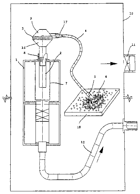
The invention will be more closely explained with the help of drawings,
depicting plc. 1 - the
pollen cleaning device in a schematic cross-section, plc. 2 - view of the
separator with circular
screen, and plc. 3 - view of the separator with conical segment.
Detailed description of the preferred embodiments
The pollen cleaning device based on this invention is comprised of the suction
unit l, made of
a vacuum cleaner in a vertical position. Inside the textile dust bag 7, which
is a standard
component of the vacuum cleaner, is inserted the filter 2, made of a filter-
paper cylinder. Into
this filter is fit the plastic reduction 8, and into its neck is fit the
plastic separator 3, comprised
of the conical part _l6 and lid 9. The reduction 8 and separator 3 may also be
joined into one
body, but separation into two parts is more practical when washing and
cleaning. Into the
separator _3 in the area of its greatest diameter is tangentially connected
the outlet of the
suction line 4 via an interchangeable reduction 17. The suction line is lead
from a plastic tube
ending with -an interchangeable plastic suction attachment S for suction of
impure pollen &. By
using the interchangeable reduction 17 with various diameters and suction
attachments 5 with
the same diameter, the underpressure suction of impure pollen 6 into the
separator 3 is
optimised in dependence on the impurity level of the pollen.
The separator _3 may be equipped with a circular metal shield 13 or the
plastic conical
segment 14 with side openings 15, arranged between the conical part 16 and lid
9.

CA 02463383 2004-04-08
WO 03/041840 PCT/CZ02/00035
J
The pollen cleaning device is assembled according to plc. 1 in a closed
underpressure
chamber 10 equipped with an underpressure ventilator 11, and the outlet 12
from the suction
unit 1, made of a tube, is led outside the underpressure chamber 10. The
pollen cleaning
proceeds in the following manner: Impure pollen 6 gathered in nature, cleaned
of large objects
such as leaves, blossom parts etc. and dried to the required dampness is
sucked up through the
suction attachment 5, suction line 4 and reduction 17 into the separator 3,
where it comes via a
tangential course up to the conical part I6. Here, the actual cleaning of the
pollen 6 occurs.
Pollen is an insulant and thus falls through the bottom opening in the conical
part 16 of the
separator 3 through the reduction _8 into the filter 2 made of a paper bag,
where it is caught.
Undesirable particles, dust, spores and micro organisms move around in the
electrostatic field
generated by friction against the plastic surface of the conical part 16 of
the separator _3 and
when the suction unit 1 is stopped, they stick to the plastic surface of the
conical part 16.
Heavily contaminated pollen b is sucked in through the suction attachment _5,
the line 4, and a
reduction _8 with a small diameter, so that the amount of contaminants does
not block the
conical part 16 of the separator 3. For clean pollen 6, the suction attachment
5, line _4, and
reduction _8 with a large diameter is used. In the case of very pure pollen
_6, it is possible to
insert it directly into the separator 3 with a spoon.
The pollen cleaning method and the pollen cleaning device are utilisable for
cleaning raw
pollen material to be used in the manufacture of medicaments.

Representative Drawing
A single figure which represents the drawing illustrating the invention.
Administrative Status

2024-08-01:As part of the Next Generation Patents (NGP) transition, the Canadian Patents Database (CPD) now contains a more detailed Event History, which replicates the Event Log of our new back-office solution.

Please note that "Inactive:" events refers to events no longer in use in our new back-office solution.

For a clearer understanding of the status of the application/patent presented on this page, the site Disclaimer , as well as the definitions for Patent , Event History , Maintenance Fee  and Payment History  should be consulted.

Event History

Description Date
Application Not Reinstated by Deadline 2007-06-18
Time Limit for Reversal Expired 2007-06-18
Deemed Abandoned - Failure to Respond to Maintenance Fee Notice 2006-06-19
Inactive: IPC from MCD 2006-03-12
Inactive: Cover page published 2004-06-11
Inactive: Notice - National entry - No RFE 2004-06-09
Inactive: Inventor deleted 2004-06-09
Application Received - PCT 2004-05-11
National Entry Requirements Determined Compliant 2004-04-08
Application Published (Open to Public Inspection) 2003-05-22

Abandonment History

Abandonment Date Reason Reinstatement Date
2006-06-19

Maintenance Fee

The last payment was received on 2005-05-20

Note : If the full payment has not been received on or before the date indicated, a further fee may be required which may be one of the following

  • the reinstatement fee;
  • the late payment fee; or
  • additional fee to reverse deemed expiry.

Please refer to the CIPO Patent Fees web page to see all current fee amounts.

Fee History

Fee Type Anniversary Year Due Date Paid Date
Basic national fee - standard 2004-04-08
MF (application, 2nd anniv.) - standard 02 2004-06-17 2004-05-05
MF (application, 3rd anniv.) - standard 03 2005-06-17 2005-05-20
Owners on Record

Note: Records showing the ownership history in alphabetical order.

Current Owners on Record
JIRI TOMEK
Past Owners on Record
None
Past Owners that do not appear in the "Owners on Record" listing will appear in other documentation within the application.
Documents

To view selected files, please enter reCAPTCHA code :


To view images, click a link in the Document Description column. To download the documents, select one or more checkboxes in the first column and then click the "Download Selected in PDF format (Zip Archive)" or the "Download Selected as Single PDF" button.

List of published and non-published patent-specific documents on the CPD .

If you have any difficulty accessing content, you can call the Client Service Centre at 1-866-997-1936 or send them an e-mail at CIPO Client Service Centre.


Document
Description 
Date
(yyyy-mm-dd) 
Number of pages   Size of Image (KB) 
Abstract 2004-04-08 1 51
Representative drawing 2004-04-08 1 21
Description 2004-04-08 3 219
Drawings 2004-04-08 2 43
Claims 2004-04-08 1 44
Cover Page 2004-06-11 2 44
Reminder of maintenance fee due 2004-06-09 1 109
Notice of National Entry 2004-06-09 1 192
Courtesy - Abandonment Letter (Maintenance Fee) 2006-08-14 1 175
Reminder - Request for Examination 2007-02-20 1 116
PCT 2004-04-08 2 73