Note: Descriptions are shown in the official language in which they were submitted.
CA 02463612 2004-04-13
WO 03/034443 PCT/IB02/04161
1
A METHOD OF OPERATING A NUCLEAR POWER PLANT
THIS INVENTION relates to a nuclear power plant. More
particularly it relates to a method of operating the nuclear power plant
when power demand decreases to zero.
The Inventor is aware of a nuclear power plant which
includes a closed loop power generation circuit configured to make use
of a Brayton cycle as the thermodynamic conversion cycle.
The nuclear power plant is typically connected to a national
grid and electricity generated by the plant must vary to correspond to
the demand from the grid.
The possibility exists that the national control centre
requires minimal delivery of electricity to the grid. In this situation, i.e.
when power demand from the grid decreases to zero, the plant will
generate house loads with no or minimal power delivery to the grid.
It is also important that the plant remain synchronised with
the grid so as to be able to satisfy a demand for power increase
relatively quickly and, to this end, that the reactor remain critical.
CA 02463612 2004-04-13
WO 03/034443 PCT/IB02/04161
2
Further, it is desirable, in the interests of efficiency, to
reduce fuel consumption when power delivery to the grid is zero. In the
context of this specification it is to be understood that zero power
delivery to the grid is intended to include both the situation when no
power is delivered to the grid and that when power delivery to the grid
is at a very low level.
According to the invention, there is provided a method of
operating a nuclear power plant, which is connected to and
synchronised with an electrical distribution grid and which has a closed
loop power generation circuit making use of helium as the working fluid
and a Brayton cycle as the thermodynamic conversion cycle, when
power demand from the grid decreases to zero, which method includes
the steps of
reducing electrical power generated by the plant to house load;
and
changing the plant from a power operation mode, in which the
Brayton cycle is self-sustaining, to a standby mode, in which the Brayton
cycle is not self-sustaining and mass flow of working fluid around the
power generation circuit is achieved by an auxiliary blower system and
in which the plant remains synchronised with the grid.
Were it not for the auxiliary blower system sustaining or
supporting the working fluid mass flow, the mass flow would diminish
to an undesirable state.
When the power generation circuit includes a reactor, a
high pressure turbine and low pressure turbine, which are drivingly
CA 02463612 2004-04-13
WO 03/034443 PCT/IB02/04161
3
connected, respectively, to a high pressure compressor and a low
pressure compressor, a power turbine drivingly connected to a
generator, a high pressure compressor recirculation line, in which is
mounted a high pressure compressor recirculation valve, and a low
pressure compressor recirculation line, in which is mounted a low
pressure compressor recirculation valve, reducing the electrical power
generated may include opening one or both of the compressor
recirculation valves. The method may further include controlling the
positions of the compressor recirculation valves so that the generator
produces house load for the plant and the power to the electrical
distribution grid is zero.
Reducing the electrical power generated may include
reducing the inventory of helium in the power generation circuit.
The nuclear power plant may include a helium inventory
control system (HICS) which can be used to increase or decrease the
helium inventory in the power generation circuit. Accordingly, reducing
the helium inventory in the power generation circuit may include
connecting a helium inventory control system in flow communication
with the power generation circuit and permitting the transfer of helium
from the power generation circuit to the helium inventory control
system, thereby to generate less power.
During this process, the mass flow through the core
decreases, which results in a decrease in nuclear power generated.
However, because the efficiency of the Brayton cycle is very low at low
mass flows, the nuclear power generated in the core is still significant.
CA 02463612 2004-04-13
' ~ 4
A Isras part of the energy oreated in the care is dumped into host
' . exahena4ro,. The aarnprsssor rscirauJ~rtion lines orra~ "internal
eiret~ts'
, , .,
with either a high mass flow or a reieti~iy high tampersturs. These two
atrcu3ts oreats the oondttion 'that the heat a~n be r~movect from the ,
system end dumped into the heat exch~n~or. Only m :malt part of the
energy gensrntrd in the pore is used to pr~aduos~ the n~ocsasary hour
load. . - ~ ~ .
This sltuatlon may lest for a rsietiv~iy ior~y time, typioaity of
9 D ~ the, order of eight hours. e~~. during the night. This means that
despite
the feat that no power fs deiiv~red to the grid, the consumption of ' . .
': nuclear fast is stilt sighifios~t.
" Changin~ the plant from a power operation mode to a
1$ standby mode may include, st'ter the pi~ant has etablllaed, crsatih~ a
transition ai~tuation where mass 'Flaw in the power psrneratton oirauit i:
" ~.. , created by the auxiliary , bivwsr system ~~rvhfia thr power turbine
still ;
gsnerstas the house ioacia, ' .
2p When the auxiliary blower system includes s normally open
- blower system in-llne valve, s pair of blowers connrctpd 1n paratisl
therewith, and a normally aioeed blower isolation valve connected tn
series with each of 'the blowers, creating the transition situation may
include . starting the blawe~rs and contr4iiing the positions of the
2~ oompressor recircuiation valves, blower system in-tins valve end blower .
iaolatfon valves. Ths auxiliary blower system may also funot9on as a
start-up blower system far use as plant start-up.
CA 02463612 2004-04-13
.
A~itsr a successtul~trensftion. the high pressur~ and the tow
prs~ssura turbtne/aomprssaor$ arc cperatin~t st st~niflaantly reduced t~,ass
flow rates, which means tow e~Ficisncy levels, end s(~niftaantiy less
en~ar~y ie dumped into the heat exc~enesr. The,svars~s core
t~mp~ratura increases and the nuclear power ~en~erated in the core
d$creasss. This means that sigr~iftosntiy less_nucleer fuel t~ oonsumcd in
this standby mode than would be conaurryed in a tow power oper~tio~
rnods. The advahtags of operating the plant tn thts state t$ that minim~t
electric power !~s 8snerated and that the plant rerrtaln~ connected '
'i 0 eteotrtcaiiy to th: ~rfd. The plant is still synchronized to the ~rid. A:
a
re~s~rlt, the plant aar~ quickly return to a condition o~f significant
stectrtoat
power produotton by closing the rscircuiation naives and switching oft the
. auxiitsry blower system. ~ '
Wlth the plant in standby rraode Tt is ready to rnske #~
transition to power operation mode. However, the time consuming .
synchrohiaatton.te not necs,ssary 'thereby pormittang th* pisr<t to react to
sn increase tn power demand ri~lstivety qulckiy since the reactor remains
critical. The power turbine stays synohronlse~d at 80 Ht, and thus no .
~d unnecessary cycling betwesr~ Q Hz arid 50 Hx to requirad,
't"ha inv~ntton v~tlll now be described, by way of exarnplo,
with r~ferenas to th~a accornpanyinp dlagrammatia drsvving which shows
a eohsrn8tlo roprssentatton of a nuclear power plant in accordance wtth
~3 xhs invention. ~ .
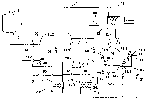
tn the dcewina, refgs'ence numeral 4 G refers ~ensrsliy to
paartt of s nuclear power plant in accordance with the invsntton.
CA 02463612 2004-04-13
WO 03/034443 PCT/IB02/04161
6
The nuclear power plant 10 includes a closed loop power
generation circuit, generally indicated by reference numeral 12, which
makes use of helium as the working fluid. The power generation circuit
12 includes a nuclear reactor 14, a high pressure turbine 16, a low
pressure turbine 18, a power turbine 20, a recuperator 22, a pre-cooler
24, a low pressure compressor 26, an inter-cooler 28 and a high
pressure compressor 30.
The reactor 14 is a pebble bed reactor making use of
spherical fuel elements. The reactor 14 has an inlet 14.1 and an outlet
14.2.
The high pressure turbine 16 is drivingly connected to the
high pressure compressor 30 and has an upstream side or inlet 16.1 and
a downstream side or outlet 16.2, the inlet 16.1 being connected to the
outlet 14.2 of the reactor 14.
The low pressure turbine 18 is drivingly connected to the
low pressure compressor 26 and has an upstream side or inlet 18.1 and
a downstream side or outlet 18.2. The inlet 18.1 is connected to the
outlet 16.2 of the high pressure turbine 16.
The nuclear power plant 10 includes a generator, generally
indicated by reference numeral 32 to which the power turbine 20 is
drivingly connected. The power turbine 20 includes an upstream side
or inlet 20.1 and a downstream side or outlet 20.2. The inlet 20.1 of
the power turbine 20 is connected to the outlet 18.2 of the low pressure
turbine 18.
CA 02463612 2004-04-13
WO 03/034443 PCT/IB02/04161
7
A variable resistor bank 33 is disconnectably connectable
to the generator 32.
The recuperator 22 has a hot or low pressure side 34 and
a cold or high pressure side 36. The low pressure side of the
recuperator 34 has an inlet 34.1 and an outlet 34.2. The inlet 34.1 of
the low pressure side is connected to the outlet 20.2 of the power
turbine 20.
The pre-cooler 24 is a helium to water heat exchanger and
includes a helium inlet 24.1 and a helium outlet 24.2. The inlet 24.1 of
the pre-cooler 24 is connected to the outlet 34.2 of the low pressure
side 34 of the recuperator 22.
The low pressure compressor 26 has an upstream side or
inlet 26.1 and a downstream side or outlet 26.2. The inlet 26.1 of the
low pressure compressor 26 is connected to the helium outlet 24.2 of
the pre-cooler 24.
The inter-cooler 28 is a helium to water heat exchanger and
includes a helium inlet 28.1 and a helium outlet 28.2. The helium inlet
28.1 is connected to the outlet 26.2 of the low pressure compressor 26.
The high pressure compressor 30 includes an upstream side
or inlet 30.1 and a downstream side or outlet 30.2. The inlet 30.1 of
the high pressure compressor 30 is connected to the helium outlet 28.2
of the inter-cooler 28. The outlet 30.2 of the high pressure compressor
is connected to an inlet 36.1 of the high pressure side 36 of the
CA 02463612 2004-04-13
WO 03/034443 PCT/IB02/04161
8
recuperator 22. An outlet 36.2 of the high pressure side 36 of the
recuperator 22 is connected to the inlet 14.1 of the reactor 14.
The nuclear power plant 10 includes an auxiliary or start-up
blower system, generally indicated by reference numeral 38, connected
between the outlet 34.2 of the low pressure side 34 of the recuperator
22 and the inlet 24.1 of the pre-cooler 24.
The auxiliary blower system 38 includes a normally open
start-up blower system in-line valve 40, which is connected in-line
between the outlet 34.2 of the low pressure side 34 of the recuperator
~ 22 and the inlet 24.1 of the pre-cooler 24. Two blowers 42 are
connected in parallel with the start-up blower system in-line valve 40
and a normally closed isolation valve 44 is associated with and
connected in series with each blower 42.
A low pressure compressor recirculation line 46 extends
from a position between the outlet or downstream side 26.2 of the low
pressure compressor 26 and the inlet 28.1 of the inter-cooler 28 to a
position between the auxiliary blower system 38 and the inlet 24.1 of
the pre-cooler 24. A normally closed low pressure recirculation valve 48
is mounted in the low pressure compressor recirculation line 46.
A high pressure compressor recirculation line 50 extends
from a position between the outlet or downstream side 30.2 of the high
pressure compressor 30 and the inlet 36.1 of the high pressure side 36
of the recuperator 22 to a position between the outlet or downstream
side 26.2 of the low pressure compressor 26 and the inlet 28.1 of the
CA 02463612 2004-04-13
WO 03/034443 PCT/IB02/04161
9
inter-cooler 28. A normally closed high pressure recirculation valve 51
is mounted in the high pressure compressor recirculation line 50.
A recuperator recirculation line 52 extends from a position
upstream of the inlet 36.1 of the high pressure side 36 of the
recuperator 22 to a position downstream of the outlet 36.2 of the high
pressure side 36 of the recuperator 22. A normally closed recuperator
recirculation valve 54 is mounted in the recuperator recirculation line 52.
The plant 10 includes a high pressure coolant valve 56 and
a low pressure coolant valve 58. The high pressure coolant valve 56 is
configured, when open, to provide a recirculation of helium from the
high pressure side or outlet 30.2 of the high pressure compressor 30 to
the inlet or low pressure side 18.1 of the low pressure turbine 18. The
low pressure coolant valve 58 is configured, when open, to provide a
recirculation of helium from the high pressure side or outlet 30.2 of the
high pressure compressor 30 to the inlet 20.1 of the power turbine 20.
In use, the plant 10 is connected to a national electrical
distribution grid (not shown) and the power supplied to the grid from the
plant is determined by a national control centre. Accordingly, the power
generated by the plant varies according to the demand received from the
national control centre.
In use, under normal demand conditions, the power
generation circuit 12 operates on a self-sustaining Brayton cycle.
CA 02463612 2004-04-13
~a
However, when tf~~a nettona! control centre requires no or
minimal dRltvery to thg grid. the power peenere~d by the plant is reduc~d
to house laed.
This cah be achieved whilst maintaining thr~ l3rayton cycle,
however, this lBade to ~xoessive fuel oonsumptlon and is undesirable.
Accordlngly.1r: this situation, the alectrioat: power, Bonarated by the phnt
ig r~iuced to housQ loads end the pfa~t fa than ahenged frot~n a power
oper~atlon mode, in which the Brayron oycls is self-sustaining. to a
standby rr~ode, ire which th~ Brayton cycle is not self sustaining and
rrie8a flow of working fluid around this power generation cirouit fe
achieved by the auxiliary blower system.
Accordingly, when s signet to receiv~od to .reduce tl~e power
generated to house Ioada, the mesa flow through the cure of xhe reactor
14 Is reduced. This is achieved by reeduelng th~a h~tium inventory in the
power g~eration circuit 'i'~ end also by cper~tn~ one or bo~kh of the
compressor racircuiation v~aivs~a 48. ~1. During this process, tho me'a
flow through th~ core x 4 decreases. ~ ,This xsautta in ~n increase in th.
everepe vote t~mperature. 7"hs resulting negative reeetivtty fesdbaok ,
from the core results in a d~crsa~se tn nuclear power ~snerated in the
cQra 14. Mowever, because the efEiclency of the -~~ayton cycle to very
low st low mass flows due to the use of the oompre'ssor recircufation
valves 48, b ~ , th~ nuaisar power ~ensrated in the oorv is mtili
al~nlfiGe~nt,
typlaslly of the order of 40 to Ba MW. A Tarps part of the energy
generated !n the cars 14 is dumped into the inter~cooler 28 and the pro~ ..
cooler 24. In addStion, ea a r~ault of the helium clrculetinp around the
aompreasors 2a, 3b, clrouita ors created with either a hl~h mesa
CA 02463612 2004-04-13
11
flow or a ralattvsly high temperature. Once the plant is stable, a
Iran=ition situation is then oreated where moss flow in the .poitv~r
generation otroult 12 Is cr~at~d by the auxiitsry blower ~yatet~n 38. To
this end, the positions of the con~preaaor rscirrutation vahrea 48, 67,
' blower eystarn In-line valve 40 and blower isolation valves 4~ er~
oontroiied and st some stage the ~rayton cycle will cease to be se(f~
sustaining and mess flow In the power saner~tion .~cfrcuit 9 ~ will be
eahieved by mr~ana of the blow~r system 38.
After a suGGasufui transition. the high pre~ure and low
pressure turbine/cornpres8ors 'i 8, 30f18, 2B are opsratin~ tt
significantly reduosd mass ftnw rates, which means~iow efficiency Iswsis
and significantly lass energy is dumped into the heat exahsn8~re .~~. 28.
Th~a.averape core tsrnperarture increases and the nuaiear power
' generated in the core decreases 'to lees then 20 MW. This means that
significantly less nuclear fuel is acnsumsd in the standby mode and the
rsaator remains critiaei. . '
When the power demand increassg, the Brayton oycir oan '
be restarted by retumin8 the' giant 'f O to a pow~r vperatlon rnodr. In
view of the fact th:rk th~ generator 32 hea remained aynahroniz~d with
the grid and the reactor 14 has remained crfxicai, the time consuming
synchronixetion ie not neoesaary thereby permitting the plant 10 to react
to an increase in power d~rnand reiativeJy quickly.
The Inventor b~Iimvs~ that by oparatin~ the nuolemr power
giant 10 in the t~enner daaQribed above, consumption of nuoisar fuel e4n
be reduoed substantially with oorrsepondin~ increases in afii~fenoy.