Note: Descriptions are shown in the official language in which they were submitted.
P.rinte~: ~~ 1 ~~fl0~ ~ D E~~ ' fD0~~~7fl.~~
1
Title' A device for nurifvin~ liquid in a liquid reservoir and a transformer
provided
with such a device.
Technical Field
The invention relates to a device for purifying liquid in a liquid reservoir,
said device
including a vacuum chamber having an inflow opening and an outflow opening
adapted
to communicate with the liquid in the reservoir through a feed conduit and a
return
conduit, respectively, a pump arranged in the return conduit, a vacuumpump
connected
with the vacuum chamber, and a filter cartridge provided with a plurality of
filter
elements, each having a flow side communicating with a central passage and a
flow
side opening into the periphery of the filter cartridge, and where the filter
cartridge is
arranged inside the vacuum chamber, the central passage of the filter
cartridge
communicating with the inflow opening of the vacuum chamber.
A high-voltage transformer is a well-known component, which is widely used as
part .
of the power supply network and as a vital part of the high-voltage
electricity grid..
High-voltage transformers may for instance also be used in factories to step
up or. step . '. .. .
down the supply voltage according to need. A high-voltage transformer is
formed of
five essential components, ie. an iron core, a winding, an insulating
material, a coolant
and a casing. It further comprises a number of other components which,
however, do
not determine the basic function. The iron core is typically a silicon iron
alloy rolled
into thin sheets of a thickness of between 0.3-0.5 mm, said plates being
stamped into
a suitable shape and assembled into an iron core. Usually the winding in the
high-voltage transformer is a copper winding, but an aluminium winding may
also be
used even though this is an unusual choice. The winding in the high-voltage
transformer is insulated. The insulating material may be made different types
of
materials, but it is typically made ofpaper wound round the conductors in the
winding.
Various materials may be used as coolant in a high-voltage transformer, but
either air
or oil is commonly used. Air is a poor coolant due to its low specific heat
~~~~~~~ v'ai~v~
CA 02464300 2004-04-21
a ~ ~~oo-2oa~
Prmte~. ~~~1Q ~D~3 DE~G~ D~t?~0~~'O~j
la
capacity and low heat transfer coefficient for which reason air is usually
only used in
small high-voltage transformers or under special conditions. Oil is far more
often
r~a CA 02464300 2004-04-21
CA 02464300 2004-04-21
WO 03/035215 PCT/DK02/00701
2
used as coolant. It is very effective coolant, the specific heat capacity and
the heat
transfer coefficient thereof being superior to those of air. The object of the
casing
of a high-voltage transformer is of course to enclose the iron core and the
winding,
but in addition thereto the casing serves as a tank for the transformer oil.
Furthermore
bushings are provided in the casing for the inlet and outlet lines of the
winding as well
as various pressure relief valves. Gauges may also be provided in the casing.
As mentioned above the transformer oil serves as a coolant for the high-
voltage
transformer. However, this is not the only function of the transformer oil, as
the
transformer oil also constitutes a vital part of the transformer insulation.
As an
example thereof, transformer oil has a dielectric constant, sr, between two
and three
unlike air or vacuum which have a dielectric constant of one. Another factor
characteristic of the transformer oil is the voltage at which voltage
breakdown occurs.
A voltage breakdown is caused by an arc arising through the transformer oil
between
two conductors or between a conductor and the casing. The voltage of
transformer oil
at which voltage breakdown occurs is typically about 150 kV/cm. However many
other factors influence the breakdown voltage size, eg. a water content of a
merely
0.01 % in oil reduces the breakdown voltage by 20%. Another factor, which may
significantly reduce the breakdown voltage, is the presence of contaminating
particles
or suspended gasses (bubbles) in the transformer oil. These contaminating
elements
occur as electric dipoles and tend to create bridges between conducting parts
at
different electrical potentials. As a result the bridges form a possible path
for an arc
and thus contribute to reducing the breakdown voltage. The breakdown voltage
in an
extremely pure transformer oil is as high as 1000 kV/cm. However, in practice
it is
impossible to maintain such a transformer oil purity in a high-voltage
transformer.
Several reasons exist as to why the oil in a high-voltage transformer becomes
contaminated. Oil is filled into the transformer at the manufacture of the
high-voltage
transformer. If suitable precautions are not taken, the oil becomes
contaminated.
Even though contamination cannot be avoided completely, much is done to
minimize
CA 02464300 2004-04-21
WO 03/035215 PCT/DK02/00701
3
contamination during all types of manufacturing processes of high-voltage
transformers, eg by ensuring that the transformer is substantially free of
particles and
dry before being filled with oil. It is, however, also necessary inter alia to
take both
relative and the absolute humidity into account during the feeding of oil.
The oil is further contaminated during service of the high-voltage
transformer.
Despite being properly dried before the oil is filled into the transformer,
the paper
insulation of the transformer windings contains an amount of water. The actual
water
content in paper insulation depends on several factors including the
temperature. In
service, a high-voltage transformer suffers an energy loss, partly in form of
a
resistive drop in the transformer winding and partly as an iron loss caused by
the
conversion of electrical energy to magnetic energy and back to electrical
energy.
Ultimately the energy loss causes a temperature change in the high-voltage
transformer. Since the size of this energy loss varies according to the load,
the
temperature changes over time. Consequently, when the high-voltage transformer
switches from being loaded to running idle a situation may arise in which the
temperature drops to a point at which the paper and the oil cannot contain the
absorbed water, whereby free water is formed in the oil. Another factor is the
variations in the temperature and the possible presence of oxygen which cause
the
transformer oil and the paper insulation to age. Ageing is the disintegration
of a
material and may thus cause the formation of decomposition products in the oil
in
form of particles, gases and water.
As mentioned above, the presence of water, particles or gas bubbles in the
transformer oil is undesirable, for which reason filtering of the transformer
oil is
required. The oil in a high-voltage transformer is typically cleaned by means
of one
of the two methods below. In one method, which has been used for a number of
years,
the oil is drained out of the high-voltage transformer and moved to an oil
treatment
system or to move an oil cleaning system to the high-voltage transformer and
to pass
the oil is through the system. However, this method is encumbered by the
significant
CA 02464300 2004-04-21
:i.
,l
4
drawback that in order to treat the oil the high-voltage transformer has to be
taken out
of service for some time. In another method, which is used nowadays for the
treatment
of oil, a filter is secured to the high-voltage transformer and through which
the oil
circulates continuously, while the transformer is in service.
It is thus commonly known to filter a liquid, while the plant, in which the
liquid is used,
is in service. It is inter alia known to provide a filter for removing
contaminat-ing
elements from the lubricating oil in connection with a lubricating device of a
combustion engine in a car. It is also known to use water traps to. remove
water for
instance from diesel oil for a diesel engine. The necessary purification
process of
transformer oil differs from that of for instance lubricating oil by the
degree of purity
required in connection with transformer oil.
Background Art
US patent No 3,249,438 discloses an apparatus for removing contaminants e.g.
water
from a fluid such as oil. The apparatus comprises filters placed inside a
vacuum
chamber, and the combination of the vacuum and oil film on the outside surface
of the
filters removes water from the oil in the form of a vapour. The vapour is
thereafter
removed from the vacuum chamber. There are not described means for controlling
liquid foam in the vacuum chamber.
US patent No 6,224,716 discloses an apparatus much like US.patent No 3,249,438
but
it also comprises a heating circuit for the oil to speed up the evaporation of
the water
from the oil. There are described pumps and valves for feeding liquid to the
vacuum
chamber and removing liquid from the vacuum chamber. There are not described
means for controlling liquid foam in the vacuum chamber.
US patent No 5,574,214 discloses an apparatus for the treatment of transformer
oil, in
which the oil is treated by being passed through a vessel containing a
conventional
AM~NDED.~~H~ET'~ ~~,~i:~z~C"''~~a ~~ ~~~~~
CA 02464300 2004-04-21
A 4a
filter material and a molecular sieve. A molecular sieve is a material which
is able to
retain molecules of a specific molecular weight. The conventional. filter
material thus
removes the particles from the transformer oil and the molecular sieve removes
the
water. This method is disadvantageous in that over time the, ,molecular sieve
is
exhausted and has to be replaced. ,
International publication No WO 00/52445 discloses an apparatus, in which a
filter
cartridge is used to filter the transformer oil. The filter cartridge contains
a filter
material such as Fuller's earth. Fuller's earth is a type of soil, which inter
alia is used
as cat litter, and which possesses the ability to absorb water very easily .
This device
is encumbered by the same drawback as the above US patent, ie that the filter
material
is exhausted and has to be replaced occasionally. The WO publication further
discloses
a vessel provided with a vacuum pump, which is used to nvnimise the gas
AI~I~NC~ED ~H~~'f'. ,lfy L!
F~r~n~ed: ~2 ~ 0~~003 DE~~:° t~O~~Cl7~ ~ ~_
.
n.::.:... . ...~.. __........
.. ..~ ..
suspension in the transformer oil.
US-A-2062934 describes a filter system where the liquid flows through disk-
like filter
.. elements from the outside of the filter elements to the inside, and where
the filter
elements are placed inside a vacuum chamber. It is mentioned that the liquid
is the oil
5 from a transformer and that the system removes water from the oil.
US-A-6224716 describes a filter system for lubricating oils where cylindrical,
coalescent filter units are placed in a vacuum chamber and where heated oil is
passed
from the inside of the filter units to the outside. It is specifically
mentioned that the
system can remove water from the oil.
~ DK patent No 156542 discloses a filtering device comprising a plurality of
stacked
filtering elements forming a filter cartridge. The disc-shaped filtering
elements each has
a central aperture forming a central passage with apertures to the inner
cavity of the
individual filtering elements in the stacked position ofthe filtering
elements. Typically,
the central passage has an inlet opening at one end and an opening sealed by
means of
_a plug at. the other end. Each filtering element has a planar outer side
adjacent the
central aperture and a corrugate side. As a result each pair of filtering
elements opens
into the central passage on one side, while closely abutting the adjacent pair
of filtering
elements on its inner side.
Description of the Invention
The device according to the invention is characterised in that the filter
cartridge is
arranged inside the vacuum chamber, the central passage of the device
communicating
with the inflow opening of the vacuum chamber.
The resulting device ensures an effective continuous removal of contaminating
particles
from the liquid and removal of the water present in the liquid, the liquid
l~~~i ~.'t~~ :i _ a ~ , ;~ v 4~
CA 02464300 2004-04-21 ~ .~ r~~~(~',~'~o0r3
.
Fri~ted~ . t12 ~ ~-2~~3'i yC~E~C ~ L f~K~20~?'t~~
5a
being evacuated from the reservoir by means of the vacuum pump and into the
central
passage and then out passed through the filter elements and onto the surface
of the filter
cartridge, whereby a large liquid surface is formed. The particles in the
liquid are
filtered off by means of the filter cartridge. The flow of liquid onto the
surface of the
S filter cartridge and the low pressure in the vacuum chamber reduce both the
solubility
of water in the liquid and boiling point of the water. As a result water is
discharged as
free water in the liquid and then boiled off from the liquid. All components
of the
device except the filter cartridge are not exhausted resulting in a long life
span of the
device. The liquid is pumped back to the reservoir from the bottom of the
vacuum
chamber.
' ~' 'y' ~~~"r' _.
CA 02464300 2004-04-21 .~ r~~ ~~~~r~a~r3
' E'r~r~ted ~~ 1 ti 20~~ ~ Q~SC ~ C~Q2~Q'~0 i
r . _ H. . . - ~..~ ..: :. .. ... :.'
6
The filter cartridge known from DK patent No 156542 may advantageously be
used.
The boiling-off of the water from the liquid may cause the formation of foam
due to the
low pressure in the vacuum chamber. This is a disadvantageous effect, as the
foam may
inter alia escape to the vacuum pump. According to the invention a first
sensor for
monitoring the foam level has consequently been provided in the vacuum
chamber. If
the foam exceeds a specific level, a pressure equalizing valve is opened and
the pressure
in the vacuum chamber is increased due to the inflowing gas.
According to the invention the vacuum pump may be connected to a vessel
adapted to
accumulate the gas being drawn out of the vacuum chamber, said vessel comrnuni-
eating with the pressure-equalising valve through a conduit. The accumulated
gas may
advantageously be used for checking the condition of the transformer,
especially if the
oil stems from a transformer. This test may inter alia provide information
about the
expected remaining life of the transformer oil and of the insulating materials
in the
transformer or indicate the fault source at faults or breakdowns.
The invention also relates to a transformer characterised in that it includes
a device of
the above type, in which the oil reservoir is the oil in a transformer. As
mentioned above
a device of this type is suitable for removing impurities from a liquid such
as a
transformer oil. The transformer oil is thus cleaned continuously and any
operation
interrupting contaminating elements are kept to a minimum resulting in
increased
system reliability.
Brief Description of the Drawi
The invention is explained in detail below with reference to the drawing,
which is a
principle drawing showing all of the essential components of invention.
w._
CA 02464300 2004-04-21 ! ~~ n ~' ~'~ ~~r.a 7 ~'' ~'-~'-1
5
~JF'rir~~ed: 02 ~~ 2(~0,D~~~ pl.~~CQ2QO'~C3H~,.
6a
Best Modes for Carrying Out the Invention
~~I~uy,~,,~,,~~,8"h ~i ~~_', ~9'e-'J 1
~~a
CA 02464300 2004-04-21 I-~~'~'-~~~r~ao.~
~Printod ,(~2-lt~r:'2003 ;DESK: r~t~~Q07t~~I,
7
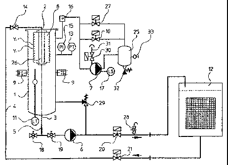
The device shown on the drawing for purifying a liquid in a reservoir 12
includes a
vacuum chamber 1 having an inflow opening 2 and an outflow opening 3, a vacuum
' pump 7, a filter cartridge 8, a feed conduit 4 and a return conduit 5. The
filter
a:
cartridge 8 is of the type mentioned in DK patent No 156542. As indicated in
the
drawing the filter cartridge 8 includes a plurality of filter elements y;. The
liquid is
passed from the reservoir 12 through a feed conduit 4 to an inflow opening 2
in the
vacuum chamber I and from there into the central passage in the filter
cartridge 8.
The vacuum pump 7 serves to maintain a low pressure in the vacuum chamber 1,
the
- low pressure evacuating the liquid from the reservoir 12 into the vacuum
chamber 1.
:"::_.,
The liquid then flows from the inner face of the filter cartridge 8 to the
outer face of
the filter cartridge 8 and drips to the bottom of the vacuum chamber 1, from
where
a pump 6 pumps the liquid out of the vacuum chamber 1 through the outflow
opening
3 and the return conduit 5 back to the reservoir 12.
By passing the liquid from the inner face to the outer face of the filter
cartridge 8 two
features are obtained, viz. the filter material filters off the particle
contamination
from the liquid and a liquid film having a large surface is formed on the
outer face of
the filter cartridge 8. The particles retainable by the filter cartridge 8
depend on the
filter material, particles of a specific minimum size being allowed to pass
freely
therethrough. The provision of a large liquid film surface on the outer face
of the
filter cartridge 8 allows for the optimum liquid amount to be subjected to the
low
pressure in the vacuum chamber one. The water in the liquid on the surface of
the
filter cartridge 8 is boiled off of the liquid, even when the liquid
temperature
considerablybelow 100°C's atwhichtemperaturewaterboils at 1 ATM. The
gaseous
water is then evacuated from the vacuum chamber t~ by means of the vacuum pump
seven.
The boiling-off of water from the liquid causes the formation of foam due to
the gas
bubbles in the liquid on the outer face of the filter cartridge 8. Together
with the
liquid the foam drips to the bottom of the vacuum chamber 1 and accumulates on
top
CA 02464300 2004-04-21
~V
CA 02464300 2004-04-21
WO 03/035215 PCT/DK02/00701
8
of the liquid. This constitutes a problem, in particular if the foam reaches
such a high
level that it comes into contact with the vacuum pump 7. A first sensor 9 has
thus
been provided in the vacuum chamber 1 for monitoring the foam level. A
pressure
equalising valve 10 is provided to reduce the foam level in the vacuum chamber
1;
said valve equalising some of the pressure in the vacuum chamber 1 when an
excessive foam level is recorded by the first sensor. The pressure
equalisation is
effected by the pressure equalising valve 10 allowing gas to flow into the
vacuum
chamber 1, whereby the foam disintegrates.
Furthermore as mentioned above, the gas present in the transformer oil is used
for
analysing the condition of the transformer, eg by indicating possible fault
sources and
estimating the remaining life of the transformer. A vessel 25 for receiving
the gas
from the vacuum chamber 1 is provided in connection with the vacuum pump 7. As
a result it is possible to continuously analyse the gas to detect any possible
fault
conditions or to analyse the gas in connection with a breakdown in order to
locate the
1 S cause of the breakdown.
The mixture of water and gases evacuated from the vacuum chamber 1 may
condense
in the sump of the vacuum pump 7. In order to prevent such a condensation air
is
supplied to the suction side of the pump 7 through the closing valve 30 and
the paper
filter 31.
The mixture of water and gases is passed to a vessel 25 from the outflow
opening of
the vacuum pump 7. This vessel is provided with a sampling valve 33 and a
pressure
equalising valve 32. The pressure equalising valve 32 serves to maintain a
specific
differential pressure between the vessel 25 and the surroundings.
The vessel further communicates with the pressure control valve 27 and the
pressure
equalising valve 10. The purpose of this connection is to return an amount of
the
evacuated gases to the vacuum chamber 1. As the gases are not extraneous, the
liquid
CA 02464300 2004-04-21
WO 03/035215 PCT/DK02/00701
9
in the vacuum 1 are not contaminated.
During the gas sampling process the mode of operation switches to sampling
mode.
The closing valve 30 is closed during sampling and only the gas being
evacuated from
the vacuum chamber 1 is pumped into the vessel 25. After a specific period of
time
the gas present in the vessel 25 corresponds to the gas present in vacuum
chamber 1.
The gas sample is extracted through the sampling valve 33.
A second sensor 11 for measuring the liquid level is further provided in the
vacuum
chamber 1. A certain minimum liquid level is required in the vacuum chamber 1
to
avoid cavitation in the pump 6. The second sensor 11 controls a level control
valve
20 ensuring that specific minimum and maximum liquid levels are maintained.
A third sensor 13 is arranged on the vacuum chamber 1 and measures the
pressure
therein. This sensor further controls the pressure control valve 27 to ensure
that a
maximum vacuum is maintained in the vacuum chamber 1. A vacuum gauge 15 is
arranged adjacent the third sensor 13 to provide a reading of the pressure in
the
vacuum chamber 1. As mentioned above, the pressure in the vacuum chamber 1
draws
out the liquid from the reservoir 12 and through the filter cartridge 8.
The control of the vacuum and the liquid flow is generally coordinated such
that a
state of equilibrium is generated in the vacuum chamber 1 at the same time as
an
acceptable liquid foam level is obtained and the pressure in the vacuum
chamber 1 is
sufficiently low to remove the water from the liquid.
In addition to the above pumps, sensors and valves a number of other
components
form part of the device. A throttle valve 14 is provided in the feed conduit 4
to reduce
the liquid flow from the reservoir 12 to the vacuum chamber 1. A closing valve
21 is
further provided in the feed conduit 4, said valve shutting-off the liquid
flow from the
reservoir 12 at the function "stop". The flow in the feed conduit 4 also has
to be
CA 02464300 2004-04-21
WO 03/035215 PCT/DK02/00701
restricted to be below the pump capacity of the oil pump 6. A level control
valve 20
is provided in the return conduit 5 for controlling the operation level of the
liquid in
the vacuum chamber 1.
Further, a manually operated closing valve 19 is provided in the return
conduit 5.
5 Jointly with a level control valve 20 the manually operated closing valve 19
may be
used to shut off the liquid during removal of the pump 6. A discharge valve 18
is used
to evacuate liquid from the vacuum chamber 1 during maintenance. The vacuum
pump
7 is provided with an oil level switch 17 switching off the vacuum pump 7, if
the oil
level in the sump of the vacuum pump becomes too low. By shutting off the
vacuum
10 pump 7 the evacuation of liquid from the reservoir 12 is stopped. A float
valve 16 is
provided to allow the foam-reducing gas to enter the vacuum chamber 1 and
further
to allow another gas, eg atmospheric air, to enter the vacuum chamber 1.
Another
function of the float valve 16 is to prevent liquid from flowing into the
vacuum pump
7. A pressure relief valve 29 is arranged between the vacuum chamber 1 and the
return
conduit S, said valve returning increasing amounts of the liquid to the vacuum
chamber 1, when the level control valve 20 is shut off during operation of the
oil
pump 6. The return conduit 5 is further provided with a sampling point 28
allowing
for a liquid sample to be extracted for analysis.
An embodiment of the invention is described above. Many modifications can be
carried out without thereby deviating from the scope of the invention. The
foam-reducing gas may for instance be atmospheric air or another gas
applicable for
that purpose. As mentioned above the gas in the transformer oil is used to
check the
condition of the transformer. If the foam-reducing gas is a known inert gas
such as
Argon, the gas is easily excluded in a future analysis. Another option is to
use the gas
already evacuated from the vacuum chamber, this gas having substantially the
same
composition as the gas to be tested and thus does not constitute a
contamination.