Note: Descriptions are shown in the official language in which they were submitted.
CA 02464637 2011-05-24
IMPACTABLE DOOR
CROSS-REFERENCE TO RELATED APPLICATION
[0001] Not applicable.
STATEMENT CONCERNING FEDERALLY SPONSORED
RESEARCH OR DEVELOPMENT
[0002] Not applicable.
FIELD OF THE INVENTION
[0003] This invention relates to industrial doors, and in particular to a
sliding
industrial door that has features built into it to make it capable of enduring
an accidental
impact.
BACKGROUND OF THE INVENTION
Sliding doors for industrial applications are well known. For example, for a
large
scale industrial freezer, in which forklift trucks are continually coming in
and out of the
freezer, insulated sliding doors have been used. The sliding doors are
typically
suspended by trolleys that have wheels engaged on tracks which are mounted to
the wall
over the doorway. There may also be tracks on the walls at the bottom of the
door to
hold the bottom of the door close to the doorway. Two panels are typically
provided
which meet in the middle of the doorway and are operated by a belt which is
power
driven at the top of the doorway and has a lower run of the belt attached to
one of the
panels and an upper run of the belt attached to the other panel, so that when
the belt is
driven, the panels move away from one another to open the doorway. When the
belt is
driven in the other direction, the panels move together toward one another to
close the
doorway. The opening of the door is typically actuated by a motion detector, a
pull cord
connected to a switch or an induction loop in the floor that senses the
presence of a
McCarthy Tetrault LLP DOCS #4125998 v. 2 -1-
CA 02464637 2011-12-16
vehicle. Although the sliding doors open and close with considerable speed,
the forklifts
also travel with considerable speed. Sometimes, when a door is opening or
closing, the
forklift may impact the door, usually adjacent to a leading edge of one of the
door panels.
When this happens, severe damage can occur to the door.
[0005] Prior art doors made to endure impacts such as this have typically been
made of fabric covered foam or other soft materials, which can absorb impact
without
significant damage to the door. However, the materials of these doors have
other
disadvantages, including that they wear out, the severity of the impact that
can be
endured is quite limited, they are not easily cleaned, they absorb moisture,
they can
contribute to mold growth which is important in a food storage facility, and
they can
become torn, and do not present a structural or aesthetic appearance.
SUMMARY OF THE INVENTION
[0006] The present invention provides an impactable sliding door that is
intended
to address these issues. In an illustrative door of the invention, there is at
least one door
panel assembly having a track panel that is suspended from the track and
slidable relative
to the track so as to open and close the doorway and a swinging panel that is
hingedly
connected to the track panel so as to pivot about a generally vertical axis
relative to the
track panel so that it can pivot in either direction out of the plane of the
track panel.
Thereby, the swinging panel can move out of the way regardless of which side
it is struck
from.
[0007] The swinging panel is illustratively held in the plane of the track
panel, in
a normal position, by a detent mechanism. The detent can be at the top of the
swinging
panel with one part of the detent on the swinging panel and the other part of
the detent on
a header that extends from the first panel inwardly over the second panel. The
detent
permits release of the door in either direction and the hinge connection of
the swinging
-2-
CA 02464637 2011-12-16
door panel to the track door panel permits the swinging door panel to pivot in
either
direction out of the plane of the track door panel, when it is impacted from
one side or the
other.
[00081 It is also illustrative that the swinging door panel have a leading
edge, that
is the edge that contacts the leading edge of the other sliding door panel in
a two door
panel assembly where the two door panels meet in the middle of the doorway, or
the edge
that contacts the threshold of the doorway in a single door panel assembly
door closing
system. The leading edge is illustratively provided by a foam or otherwise
compressible
and impact-absorptive material, which may be covered with a fabric. Each of
the track
and swinging door panel sections may primarily be made, however, of a
structurally rigid
material. Illustratively, if the door is to be used in a freezer or
refrigerated room
application, the material is an insulating material and should be of light
weight to reduce
its inertia and therefore the accelerating force necessary to swing it open
when it is
impacted. The leading edge may also be provided with a pressure responsive
sensor that
detects if the leading edge has been compressed or impacted, and a sensor may
also be
provided that senses whether the swinging panel has been swung out of the
plane of the
track panel.
[00091 In addition, it is an alternative that an impact resistant sheet be
added to
the outside, on both sides of the second panel, in the area of the second
panel which is
most likely to be hit by a fork lift, that is in the area of about the lower
half of the door
and over substantially the entire surface area of the structurally rigid part
of the second
door panel. For example, a 1/8 inch thick sheet of ultra high molecular weight
polyethylene is such a material.
-3-
CA 02464637 2011-12-16
[0010] A soft leading edge of each door panel also contributes to sealing of
the
door when it is closed, either against the threshold of the doorway if it is a
side closing
door (having one door closing assembly), or against the leading edge of the
other door
panel assembly if it is a center closing door (having two door panel
assemblies). The
leading edges of the door panels may be provided with tubular or other
structures that
overlap when the doors are closed for better sealing.
[0011] In another embodiment of the invention, the entire door panel assembly,
including both the first and second panels, is able to be swung about a
horizontal axis in
at least one direction. In an illustrative embodiment, the horizontal axis is
provided by
the connection between the trolley wheels and the track, which is a
conventional
connection for sliding industrial doors, each trolley wheel having an outer
circumference
that is concave so that the wheel can engage a similarly shaped convex rail of
the track
and be guided by the rail and pivot about the horizontal rail. The mating
concave and
convex shapes permit rotation of the trolley wheels about the rail so that the
door panel
assembly can be swung about a horizontal axis in the direction away from the
adjacent
wall to which the track is mounted.
[0012] Another embodiment of the present invention is that the bottom of the
door is connected in a releasable fashion to a track that is fastened to the
wall so that if
the door is impacted and swung away from the wall, the connection can release.
When
the door is pivoted back into its normal operating position, which is
generally in a vertical
plane adjacent to the wall, the connection will automatically reengage to hold
the bottom
of the door adjacent to the wall as the door slides parallel to the wall and
parallel to the
doorway opening in the wall that the door closes. A feature can also be
included that will
-4-
CA 02464637 2011-12-16
automatically pivot the door back into a vertical plane, such as a re-
engagement member
that re-engages the door with the track when the door is fully opened.
[0012A] In a first broad aspect of the present invention, there is provided a
laterally sliding door for closing off a doorway, comprising: a track panel
that extends
vertically for substantially the height of the doorway and horizontally
between an inward
edge of the track panel and an outward edge of the track panel so as to cover
a portion of
the doorway when the door is closed; a header for mounting the track panel to
a track
along which the track panel slides laterally when opening and closing the
door; one or
more hinges at the inward edge of the track panel, the inward edge being the
edge which
is in the direction of door closing; and a swinging panel pivotally attached
to the hinges
of the track panel at the inward edge of the track panel, the swinging panel
being
pivotable from the plane of the track panel in either direction about a
substantially
vertical axis through the one or more hinges of the track panel when the
swinging panel is
impacted from one side or the other by a forklift truck so as, in the event of
an impact by
a forklift truck from either side, to absorb a portion of the impact and move
out of the
way of the forklift truck; wherein the track panel and swinging panel can
pivot in at least
one direction about a substantially horizontal axis.
[0012B] In a second broad aspect of the present invention, there is provided
a laterally sliding door for closing off a doorway, comprising: a track panel
that extends
vertically for substantially the height of the doorway and horizontally
between an inward
edge of track panel and an outward edge of the track panel so as to cover a
portion of the
doorway when to door is closed; a header for mounting the track panel to a
track along
which the track panel slides laterally when opening and closing the door; one
or more
hinges at the inward edge of the track panel, the inward edge being the edge
which is in
-5A-
CA 02464637 2011-12-16
the direction of door closing; and a swinging panel pivotally attached to the
hinges of the
track panel at the inward edge of the track panel, the swinging panel being
pivotable from
the plane of the track panel in either direction about a substantially
vertical axis through
the one or more hinges of the track panel when the swinging panel is impacted
from one
side or the other by a forklift truck so as, in the event of an impact by a
forklift truck from
either side, to absorb a portion of the impact and move out of the way of the
forklift
truck; further comprising a releasable mechanism which holds the bottom of the
door
panel assembly so that the door panel assembly is in a substantially vertical
plane in a
normal position of the door panel assembly; wherein the mechanism comprises a
rail
mounted to a wall adjacent to the door panel assembly and a leaf spring
mounted to the
door panel assembly, with a keeper on the end of the leaf spring that is
engaged with the
rail in the normal position of the door panel assembly.
[0012C] In a third broad aspect of the present invention, there is provided A
laterally sliding door for closing off a doorway, comprising: a track panel
that extends
vertically for substantially the height of the doorway and horizontally
between an inward
edge of the track panel and an outward edge of the track panel so as to cover
a portion of
the doorway when the door is closed; a header for mounting the track panel to
a track
along which the track panel slides laterally when opening and closing the
door; one or
more hinges at the inward edge of the track panel, the inward edge being the
edge which
is in the direction of door closing; and a swinging panel pivotally attached
to the hinges
of the track panel at the inward edge of the track panel, the swinging panel
being
pivotable from the plane of the track panel in either direction about a
substantially
vertical axis through the one or more hinges of the track panel when the
swinging panel is
-5B-
CA 02464637 2011-12-16
impacted from one side or the other by a forklift truck so as, in the event of
an impact by
a forklift truck from either side, to absorb a portion of the impact and move
out of the
way of the forklift truck; wherein the track panel is fixed to the header and
the header can
pivot in at least one direction about a substantially horizontal axis.
[0013] These and other features and advantages of the invention will be
apparent
from the detailed description and drawings.
BRIEF DESCRIPTION OF THE DRAWINGS
[0014] Fig. IA is a front plan view of a two door panel assembly center
closing
door of the invention suspended from a track;
[00151 Fig. I B is a perspective view of the door of Fig. 1 A;
[0016] Fig. 1C is like Fig. 1B, but with the swing panels of both door panel
assemblies swung inwardly;
[0017] Fig. 1D is like Fig. 113, but with the swing panels of both door panel
assemblies swung outwardly;
[0018] Fig. 2 is a detail view of the top portion of Fig. 1B;
[0019] Fig. 3 is view like Fig. 2, but showing the track, trolleys and door
panels
with the door headers removed;
[0020] Fig. 4 is a perspective view of the left-hand lead trolley for
suspending a
door assembly;
[0021] Fig. 5 is a perspective view of the right-hand lead trolley for
suspending
the right-hand door assembly;
[0022] Fig. 6 is a perspective view of a standard trolley which is used to
suspend
both door assemblies from the track;
-5C-
CA 02464637 2011-12-16
[0023] Fig. 7A is an end view of the left-hand lead trolley shown in Fig. 4;
[0024] Fig. 7B is an end view of the track and drive components of the door;
-5D-
CA 02464637 2004-04-16
[0025] Fig. 8 is a perspective view of the left-hand door assembly of Fig. 1
with
the swinging panel in the normal position, and without the track or trolleys;
[0026] Fig. 9 is a detail view of a top portion of the assembly of Fig. 8;
[0027] Fig. 1OA is a view like Fig. 9, but with the header and sealing
elements
removed;
[0028] Fig. I OB is a detail view of Fig. 1 OA in the top hinge area;
[0029] Fig. 11 is a perspective view of a hinge for the door assembly, each
door
panel assembly having two such hinges, one at the top and one at the bottom
between the
two panels;
[0030] Fig. 12A is a top schematic view illustrating the door with the
swinging
panel swung open and illustrating the gas spring;
[00311 Fig. 12B is a view like Fig. 12A, but with the swinging panel in the
normal, closed position;
[0032] Fig. 12C is a top plan detail view of the detent for holding the
swinging
panel in the normal position, not showing the header so that the detent spring
is visible;
[0033] Fig. 12D is a side view of the detent, showing the detent spring bolted
to
the header;
[0034] Fig. 12E is a partial perspective view illustrating the detent spring
fixed to
the header; and
[0035] Fig. 13 is a left end view of the left door panel assembly shown in
Fig. 1
illustrating a track secured to the adjacent wall near the bottom of the door
panel
assembly and a releasable spring lever secured to the bottom of the door which
engages
the track.
McCarthy Tetrault LLP TDO-RED #8227078 v.1 -6-
CA 02464637 2011-12-16
DETAILED DESCRIPTION OF AN ILLUSTRATIVE EMBODIMENT
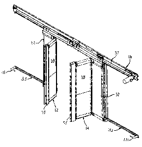
[0036] Figs. 1 A-D illustrate a door 10 including a left door panel assembly
12 and
a right door panel assembly 14. The two door panel assemblies 12 and 14 are
identical
mirror images of one another. The door panel assemblies 12 and 14 are
suspended from
a track 16 in well-known manner by standard trolleys 18 at the outward top
sides of each
door panel assembly 12 and 14 and by a left-hand trolley 20 at the inward top
side of the
assembly 12 and by a right-hand trolley 22 at the inward top side of the
assembly 14.
The track 16 is bolted or otherwise affixed to a wall 30 (see Fig. 13) and,
illustratively, a
lower rail 33 (Fig. 13) is also affixed to the wall 30 at the sides of the
doorway opening,
the lower rail 33 engaging a leaf spring extension of the door panel assembly
to hold the
lower end of the door panel assembly adjacent to the wall 30, as further
described below.
In well known fashion, the track 16 on each side of center angles down
slightly toward
center (in a bi-part door; down toward the closed side in a single part door)
so that the
bottom of the door is closer to the floor when it is closed, to compress
elastomeric seal
strips 141 (Fig. 13) at the bottom of the door against the floor.
[0037] Referring to Figs. 2-7B, the trolleys illustrated in Figs. 4-7 are
affixed to a
header 50 which is attached to the top of the track panel 52 of the door panel
assembly 12
or 14 as described below. Each trolley 18, 20, and 22 includes a pair of
rollers 32, each
of which has a concave groove which defines its circumference. Each roller 32
receives a
convex rail 34 (Figs. 2 and 3) of the track 16. The shape of the rail 34
matches the
convex shape of the circumference of each roller 32 such that the door panel
assemblies
14 can swing in a direction away from the wall 30. The wall 30 being adjacent
to the
inside surfaces of the door 10 obviously keeps the door panels 12 and 14 from
swinging
in the direction toward the wall 30. When swinging about the axis defined by
the
-7-
CA 02464637 2004-04-16
concave surfaces of the rollers 32 and convex surface of rail 34, the door
panel
assemblies 12 and 14 swing about a horizontal axis, since the rail 34 and
rollers 32 define
an axis which has its orientation horizontal. As illustrated in Fig. 7A, the
trolleys 18, 20,
and 22 may also be provided with spacers 36 which, keep the rollers 32 on the
rail 34 in
case an impact should ever tend to lift or dislodge the rollers 32 from the
rail 34.
[00381 The door panel assemblies 12 and 14 are driven toward one another to
close the doorway or away from one another to open the doorway (since they
close in the
middle of the doorway) by a power operated belt 37 in conventional fashion.
The left-
hand lead trolley 20 and the right-hand lead trolley 22 have respective drive
attachments
40 and 42, with the attachment 40 being attached to the upper run of the drive
belt 37 and
the attachment 42 being attached to the lower run of the drive. belt 37. When
the drive
belt 37 is driven by an electric motor 39 (Fig. 7B) in conventional fashion,
for example to
open the door, the upper run of the belt 37 moves to the right and the lower
run moves to
the left, driving the respective door panel assemblies 12 and 14 in the same
respective
directions. The opposite occurs when the door is closed, and the belt is
driven in the
opposite direction. The drive mechanisms, sensors (e.g., the motion detector
that actuates
the opening of the door), and related circuitry and hardware for opening and
closing the
door are well known and conventional. Any type of drive, sensors and circuitry
could be
used. Also illustrated in Figs. 2 and 3 is an e-chain 46 which is a cable
carrier that
permits routing wires to the movable door assemblies 12 and 14 in a movable
fashion,
also well known in the art, and any suitable means of supplying power to the
moving
components of the door that require power could be used.
[00391 Referring also to Figs. 8 and 9, which show only the door panel
assembly
12. The door panel assembly 14, which is the mirror image of assembly 12, is
the same
McCarthy Tetrault LLP TDO-RED #8227078 v.1 -8-
CA 02464637 2011-12-16
and this description applies to it also except as otherwise noted. Each door
panel
assembly includes a header 50 at its top, to which the trolleys are bolted or
otherwise
affixed. The header 50 is bolted or otherwise affixed to the track panel 52 of
the
assembly 12. The header 50 has a beam section 54 which extends for
substantially the
entire width of the door panel assembly 12 and, in the area over the track
panel 52 has
flanges 56, illustratively on both sides of the panel 52 which are bolted to
the panel 52, or
otherwise suitably affixed. Flanges 56 are provided on both sides of the panel
52 and the
top of the panel 52 is inserted between the flanges 56, and the bolts may
either extend all
the way from one flange 56 to the other, or the bolts may extend into the
panel 52
through holes in each flange 56 if separate bolts are used. Separate bolts may
be an
alternative in a refrigeration application so that heat is not conducted from
one end of the
bolt on one side of the door to the other.
[00401 The entire door panel assembly including the track panel 52 and the
swinging panel 58 is supported from the track 16 by the header 50. Thus, the
swinging
panel 58 is essentially cantilevered from the track panel 52. Suitable weather
stripping or
other sealing means (not shown for clarity) is illustratively provided between
the top of
the door panel assembly and the extending portion of the header 50, the
exending portion
being the portion that is inward from the flanges 56, over the panel 58, to
seal off the area
between the extending portion of the header 50 and the portion of the door
panel
assembly which is not directly affixed to the header 50.
[0041] Referring to Fig. 1 OA, it is an alternative that if the door panel
assembly is
to be used for a refrigerated application, that it be an insulating door. To
that end, each
door panel 52 and 58 has a core 62 (e.g., 4 inches thick) of an insulating
material such as
expanded polystyrene (eps). For strength and appearance, the core 62 is
laminated on
-9-
CA 02464637 2011-12-16
each of its two opposite side faces with a fiberglass skin 64. Steel or other
high strength
material reinforcing strips 66 are laminated to the tops and to the bottoms of
the
fiberglass skins 64 of each panel 52 and 58, as it is in these areas that the
hinges are
attached to the door panels 52 and 58. The metal reinforcing strips 66 help
prevent tear
out of the hinges in the case of a severe impact. In addition, end caps 68 and
70, which
may be made of steel, another metal, or plastic, are illustratively provided
on the outward
end of panel 52 and over the inward end of panel 58. This construction also
helps
provide a door of low weight and therefore low inertia that requires a
relatively low
accelerating force to get out of the way when it is struck. Other
constructions could also
be used, and the panels could be hard sided or soft-sided.
[00421 The end cap 70 over the inward end of panel 58 mounts at its inward
side,
a fabric covered foam pad 72 which serves as the leading edge of the assembly
12. The
end caps 68 and 70 are channels into which the outward end of the
eps/fiberglass
lamination of panel 52 and the inward end of the eps/fiberglass lamination of
panel 58 are
respectively inserted and adhered or otherwise fixedly attached. As shown in
Figs. 1 C,
1 D and I OA, the inward or exposed end of each foam pad 72 may be radiused
with a
convexity, and tubes 73 and 75 may be provided in sleeves secured to the
leading edges,
one on one side and the other on the other side of the respective leading
edges, on the
respective assemblies 12 and 14, so that they overlap when the panels are
closed to
provide a better seal when closed. Also, since both leading edges are made of
foam, they
may be precompressed with each closing of the door, to create a better seal.
Also, as is
known in the art, each leading edge may be provided with a pressure tube 77
(Figs. 8 and
1 OA) having a sensor that detects pressure changes in the tube 77 to detect
if the leading
-10-
CA 02464637 2004-04-16
edge has been compressed, for example by bumping into a vehicle, to trigger
opening of
the door.
[0043] The panel 58 also has a gas spring attachment 74 and a center detent
block
76 attached to its top. Any suitable means of attachment may be used, and as
illustrated,
the gas spring attachment 74 is attached by being mounted on a sheet metal
yoke that is
adhered to the plates 66 or otherwise affixed thereto, and the detent block 76
is also
mounted on the bent-up flange of a yoke that is adhered or otherwise fixedly
attached to
the strips 66. The yokes 78 and 80 may have legs which extend on both sides of
the
panel 58 for a very secure connection with adhesive, bolts, or other suitable
means, or
may be attached to the flanges 98 of the hinge 96 for a secure connection with
the door
panel 58.
[0044] Figs. 12A and 12B illustrate the gas spring 82. The gas spring 82 is a
constant force compression spring, and other types of compression springs or
other
centering mechanisms may be used to bias the panel 58 back into the plane of
the panel
52 if it is swung one way or the other out of the plane of panel 52. One end
of the gas
spring 82 is attached to the gas spring attachment 74, and the other end is
attached to the
header 50 so that the hinge axis of the panel 58 relative to the panel 52 is
on a line
between the two ends of the gas spring when the panel 58 is aligned in the
plane of the
panel 52, as shown in Fig. 12B. It is also noted in Fig.. 12A that the inward
edge of panel
52 has a seal 86 that presents an inward facing convex surface, and the
outward end of
panel 58 has a seal 88 with an outward facing concave surface that mates with
the convex
surface of the seal 86, the radii of the concave and convex surfaces being
centered on the
hinge axis of the panel 58 relative to the panel 52. This helps seal the space
between the
outward end of the panel 58 and the inward end of the panel 52 when the door
is closed
McCarthv Tetrault LLP TDO-RED #822 7078 v.1 -11-
CA 02464637 2011-12-16
with the panel 58 in the plane of the panel 52 as shown in Fig. 12B. The gas
spring 82
biases the panel 58 into the plane of the panel 52 regardless of whether the
panel 58 is
swung clockwise or counter-clockwise relative to the panel 52.
[00451 In addition, heat tape 97, illustratively of the self-regulating type,
may be
provided at areas of the door where frost or ice may otherwise form. This may
include,
for example, on the cold side at the outside corner of the panel 52, running
vertically
down the corner for substantially the height of the panel 52 (illustrated in
Fig. 12A),
inside the seal 86 running vertically for substantially the height of the seal
86 (illustrated
in Fig. 12A), and in the bottom of each of the panels 52 and 58 running
horizontally
along the bottom surfaces, inside the door illustratively (not shown). A bulb
seal 99 (Fig.
12A) may also be provided at the corner of each panel 52 that extends toward
the wall 30
of the opening in which the door is installed, so as to seal against the wall
when the door
is shut. The door may be installed in the opening so that is moves slightly
away from the
wall and from the floor so that the door seals only contact the adjacent walls
and floor in
the closed position of the door.
[00461 The centered detent block 76 is also illustrated in Figs. 12A and 12B
and
is further illustrated in Figs. 12C-E. The block itself is illustratively made
out of a hard
and lubricious plastic material (e.g., UHMW polyethylene) so that it can slide
easily on
the lead-in ramps of the spring detent 90 and snap positively into engagement
with the
spring 90 in the center position. The spring 90 is bolted or otherwise
suitably fastened to
the header 50 by a bracket 92. The block 76 (shown by itself in Fig. 12E
relative to spring
90) is attached to the top of the swinging panel 58 and rides up on the ramped
sides of the
spring 90 when it is returning to the centered position, and when it reaches
the center of
the spring 90, it snaps into the centered position shown in Figs. 12C and 12D.
The spring
-12-
CA 02464637 2011-12-16
90 flexes to release it from the centered position upon impact or other force
sufficient to
overcome the detent, in either direction. In addition, a magnet 101 can be
embedded or
fastened to the block 76 or elsewhere on the panel 72 and a magnetically
actuated reed
switch installed on the header 50 that is actuated by the magnet, so as to
provide an
electrical signal indicative of whether the panel 58 is in the plane of the
panel 52 or is
swung out of that plane.
[00471 Referring to Figs. 10A, 10B, and 11, the hinges 96 are as illustrated
in Fig.
11. To fit these to the door panels, the two (upper and lower) outward corners
are cut out
of the panel 52 to form a recess so as to substantially close the gap between
the inward
end of panel 52 and the outward end of swinging panel 58. Any remaining gap is
substantially closed by the seals 86 and 88 as described above. The hinge 96
has opposed
yokes that receive the thickness of the panels 52 and 58, over the reinforcing
panels 66,
and the yoke flanges 98 of the hinge are bolted or otherwise suitably affixed
to the
respective panels 52 and 58. On each side of the assembly 12, both the upper
hinge 96 at
the upper corner of the panel 52 and the lower hinge 96 at the lower corner of
the panel
52 may be covered, for example by a rubber or other material cover, on both
sides of the
hinge so as to weatherstrip the hinge area to prevent heat transfer or any
significant open
spaces at those locations. The axis of hinge pin 102 defines the vertical axis
about which
panel 58 hinges in or out relative to the panel 52. The hinge pin 102 at the
upper hinge
96 is coaxial with the hinge pin 102 at the lower hinge 96.
[00481 Referring to Fig. 13, at the bottom of each door panel assembly 12 and
14,
there is illustratively provided a rail 33 which is bolted or otherwise
suitably affixed to
the wall 30. The rail 33 runs lengthwise for at least the length of travel of
each door
assembly 12 or 14 on the respective side of the doorway and serves to hold the
respective
-13-
CA 02464637 2004-04-16
door assembly 12 or 14 adjacent to the wall 30 for its entire back and forth
travel, in a
generally vertical orientation. Rail 33 defines a downwardly facing shoulder
110 which
faces toward the wall 30 and behind which a keeper 114 is received from the
bottom of
the shoulder 110. The keeper 114 is made of a hard and lubricious plastic
material, for
example UHMW polyethylene, and is fixed to the free end of a cantilever spring
116.
The cantilever spring 116 is secured to the bottom of the door panel 52 at the
bottom
outward corner with bolts or other suitable means, by means of plate 118. A
wear block
120 is also mounted on the inward side of the bottom outward corner of the
panel 52,
which is also made of a hard and lubricious plastic material like UHMW
polyethylene,
which rubs on the outer surface 122 of the rail 33 as the door assembly 12
travels back
and forth. The UHMW wear piece 120 may extend all the way across the thickness
of
the panel 52 as illustrated in Fig. 13, with the plate 118 fitting in a groove
of the wear
piece 120.
[00491 In any event, the door assemblies 12 and 14, being fitted with the
releasable connection provided by the rail 33 and spring 116 arrangement, can
be easily
dislodged from the rail 33 if it is hit on its inward side, i.e. its side
facing the wall 30. If .
so, the slightly angled surface 124 on the keeper 114 cams against the
inwardly facing
surface of the shoulder 110 to flex spring 116 downwardly as door assembly 12
pivots
away from the wall 30, about the horizontal axis provided by the wheels 32 and
rail 34.
The door assemblies 12, 14 are thereby released from being held adjacent to
the wall 30.
When the obstruction is removed, the door assemblies 12, 14 are free to rotate
back to
their position adjacent to the wall 30, and when they do, the keeper 114 cams
on the
angled surface 126 of the rail 33, which flexes the spring 116 downwardly and
permits
keeper 114 to reengage behind the inwardly facing surface of the shoulder 110,
back into
McCarthy Tetrautt LLP TDO-.RED #8227078 v.1 -14-
CA 02464637 2011-12-16
the position shown in Fig. 13. As shown in Fig. 1 B, re-engagement members 111
may be
provided near the ends of the rail 33 that cam on the wear pieces 120 when the
door is
near fully opened to move the door panel assemblies 12 and 14 back toward the
wall 30
and the keeper 114 back into re-engagement with the rail 33.
[0050] The leading edge may be approximately six inches, and the entire width
of
the second panel may be approximately 30 inches, for example, with the first
panel that is
supported by the trolleys from the track, also being about 30 inches wide or
so, but any
dimensions may be applied to a door of the invention. In addition, an impact
plate 133 as
shown in Fig. IA may be provided covering at least the lower portion of each
swinging
panel 58 over the fiberglass skins, to absorb impacts and preserve the surface
finish. The
impact plates are illustratively made of a tough material, such as 1/8 inch
thick UHMW
polyethylene.
[0051] Many modifications and variations to the illustrative embodiment
described will be apparent to those skilled in the art. Therefore, the
invention should not
be limited to the embodiment described, but should be defined by the claims
which
follow.
-15-