Language selection

Search

Patent 2464754 Summary

Third-party information liability

Some of the information on this Web page has been provided by external sources. The Government of Canada is not responsible for the accuracy, reliability or currency of the information supplied by external sources. Users wishing to rely upon this information should consult directly with the source of the information. Content provided by external sources is not subject to official languages, privacy and accessibility requirements.

Claims and Abstract availability

Any discrepancies in the text and image of the Claims and Abstract are due to differing posting times. Text of the Claims and Abstract are posted:

  • At the time the application is open to public inspection;
  • At the time of issue of the patent (grant).
(12) Patent: (11) CA 2464754
(54) English Title: ACTUATOR AND CONTROL FOR POWER DECKLID PULLDOWN
(54) French Title: ACTIONNEUR ET COMMANDE D'ABAISSEMENT DE COUVERCLE DE COFFRE
Status: Expired and beyond the Period of Reversal
Bibliographic Data
(51) International Patent Classification (IPC):
  • E05F 15/611 (2015.01)
  • E05F 01/10 (2006.01)
(72) Inventors :
  • OBERHEIDE, G. CLARKE (United States of America)
(73) Owners :
  • INTIER AUTOMOTIVE CLOSURES INC.
(71) Applicants :
  • INTIER AUTOMOTIVE CLOSURES INC. (Canada)
(74) Agent:
(74) Associate agent:
(45) Issued: 2010-08-10
(86) PCT Filing Date: 2002-11-06
(87) Open to Public Inspection: 2003-05-15
Examination requested: 2007-10-31
Availability of licence: N/A
Dedicated to the Public: N/A
(25) Language of filing: English

Patent Cooperation Treaty (PCT): Yes
(86) PCT Filing Number: 2464754/
(87) International Publication Number: CA2002001688
(85) National Entry: 2004-04-26

(30) Application Priority Data:
Application No. Country/Territory Date
60/332,642 (United States of America) 2001-11-06

Abstracts

English Abstract


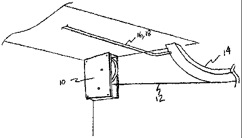
A drive assembly moves a vehicle closure panel from an open to a closed
condition. The drive assembly has a housing and a motor mounted on the
housing. A drum and gear assembly is rotatably mounted on the housing. The
drum and gear assembly has a drum having a helical groove, a gear in driving
engagement with the motor, and a spring biasing the drum in a winding
direction relative to the gear. The drum and gear have a lost motion
connection therebetween. A cable has an end connected to the closure panel and
an opposite end connected to the drum about the helical groove in the winding
direction. The drum rotates in the winding direction relative to the
stationary gear as the closure panel is manually moved from the open to the
closed condition with the spring maintaining a cable tension. The drum and
gear rotate together in the winding direction upon energizing the motor
effecting powered movement of the closure panel to the closed condition. The
motor is afterwards energized in an opposite direction counter-rotating the
gear relative to the drum back to a start position.


French Abstract

Un ensemble entraînement déplace un panneau de fermeture de véhicule, d'un état ouvert à un état fermé. Cet ensemble comporte un corps, et un moteur monté sur celui-ci. Un ensemble tambour et engrenage est monté rotatif sur le corps. L'ensemble tambour et engrenage comporte un tambour pourvu d'une rainure hélicoïdale, un engrenage en prise avec le moteur et un ressort sollicitant le tambour dans un sens d'enroulement par rapport à l'engrenage. Le tambour et l'engrenage comportent entre eux une pièce intermédiaire de mouvement à vide. Un câble présente une extrémité reliée au panneau de fermeture, et une extrémité opposée reliée au tambour par enroulement autour de la rainure hélicoïdale. Le tambour tourne dans le sens d'enroulement par rapport à l'engrenage fixe à mesure qu'on referme manuellement le panneau de fermeture, le ressort permettant de maintenir le câble tendu. Le tambour et l'engrenage tournent ensemble dans le sens d'enroulement lors de l'excitation du moteur entraînant la fermeture mécanique du panneau de fermeture. Ce moteur est ultérieurement excité dans le sens inverse pour faire tourner l'engrenage de manière contrarotative par rapport au tambour vers sa position de départ.

Claims

Note: Claims are shown in the official language in which they were submitted.


What is claimed is:
1. A drive assembly for moving a vehicle closure panel between open and closed
conditions, said drive assembly comprising:
a housing;
a motor mounted on said housing;
a drum and gear assembly rotatably mounted on said housing for movement in
a winding direction, said drum and gear assembly comprising a drum having a
helical
groove and a gear in driving engagement with said motor, said drum and said
gear
having a lost motion connection defined therebetween to allow manual movement
of
said drum relative to said gear in said winding direction; and
a cable having an end fixedly secured to the closure panel and an opposite end
fixedly secured to said drum to wind said cable about said helical groove
during
movement of said drum in said winding direction for moving the closure panel
between the open and closed conditions.
2. A drive assembly as set forth in claim 1 including a spring extending
between
said drum and said gear for biasing said drum in said winding direction
relative to
said gear.
3. A drive assembly as set forth in claim 2 wherein said drum rotates in said
winding direction relative to said gear to prevent slack in said cable
resulting from
manual movement of the closure panel between the open and closed conditions.
6

4. A drive assembly as set forth in claim 3 wherein said drum and said gear
rotate together in said winding direction upon energizing said motor for
effecting a
powered movement of the closure panel to the closed condition.
5. A drive assembly as set forth in claim 4 wherein said drum is sized to
rotate
less than one revolution to effect said powered movement of the closure panel
from
the open to the closed condition.
6. A drive assembly as set forth in claim 5 wherein said drum includes a tab
for
engaging said gear to cause rotation of said drum in said winding direction in
response to rotation of said gear in said winding direction during said
powered
movement of the closure panel between the open and closed conditions.
7. A drive assembly as set forth in claim 6 wherein said gear includes a tab
extending axially to engage said tab on said drum to cause rotation of said
drum in
said winding direction in response to rotation of said gear in said winding
direction
during said powered movement of the closure panel between the open and closed
conditions.
8. A drive assembly as set forth in claim 7 wherein said motor is energized in
an
opposite sense to counter-rotate said gear relative to said drum back to a
start position
after said powered movement of the closure panel to the closed condition,
wherein
said start position said tab of said drum is presented for immediate
engagement of said
tab of said gear.
7

9. A drive assembly as set forth in claim 8 including spaced apart side plates
for
rotatably supporting said drum and gear assembly therebetween.
10. A drive assembly as set forth in claim 9 including an axle for rotatably
supporting said drum and gear assembly between said side plates.
11. A drive assembly as set forth in claim 10 wherein said side plates include
an
aperture for mounting said motor therethrough.
12. A drive assembly as set forth in claim 11 including a driving force
multiplying
connection defining said driving engagement between said motor and said drum
and
gear assembly for multiplying by a preselected ratio the rotations of said
drum and
gear assembly relative to said motor.
13. A drive assembly as set forth in claim 12 wherein said driving force
multiplying connection includes a first pinion mounted to an output shaft of
said
motor for providing said driving engagement between said motor and said drum
and
gear assembly.
14. A drive assembly as set forth in claim 13 wherein said driving force
multiplying connection includes a driven gear mounted on said axle for
providing said
driving engagement between said motor and said drum and gear assembly.
8

15. A drive assembly as set forth in claim 14 wherein said driving force
multiplying connection includes a second pinion gear coaxially mounted to said
driven gear for providing said driving engagement between said motor and said
drum
and gear assembly.
16. A drive assembly as set forth in claim 15 wherein said driving force
multiplying connection includes a drive gear rotatably coupled to said side
plates for
providing said driving engagement between said motor and said drum and gear
assembly.
17. A drive assembly as set forth in claim 16 wherein said driving force
multiplying connection includes a drive pinion coaxially mounted to said drive
gear
and meshingly engaged with said gear of said drum and gear assembly for
providing
said driving engagement between said motor and said drum and gear assembly.
18. A drive assembly as set forth in claim 17 wherein said driving force
multiplying connection includes a first belt trained about said first pinion
and said
driven gear and a second belt is trained about said drive gear and said second
pinion
for providing said driving engagement between said motor and said drum and
gear
assembly.
9

Description

Note: Descriptions are shown in the official language in which they were submitted.


CA 02464754 2004-04-26
WO 03/040503 PCT/CA02/01688
ACTUATOR AND CONTROL FOR POWER DECKLID PULLDOWN
BACKGROUND OF THE INVENTION
Field of Invention
This invention relates to an actuator and a control for a power decklid.
Background of Invention
It is common to provide a vehicle with a trunk or deck lid that has an
automatic power releasing latch. Activation of the power latch releases the
deck lid.
Springs located in the hinges urge the deck lid to move into the fully open
condition.
Systems have been proposed that provide a mechanism for automatically
closing the deck lid to a secondary closed position whereupon the latch
automatically
cinches the deck lid to the primary closed and sealed position. Such systems
include
United States patent nos. 4,739,585 and 4,823,059.
United States Patent No. 4,823,059 discloses a cable driven system whereby a
cable is wound about a drum having the remote end connected to the hinge of
the
deck lid. An actuator drives the drum to wind the cable and pull the deck lid
down to
engage the latch. The current of the motor is monitored to determine when the
deck
lid reaches the secondary closed condition, the primary closed condition and
also
detects obstacles in the path of the closing deck lid.
The prior art systems provide a direct drive connection between the actuator
and the deck lid. Thus, when the deck lid is being closed manually, the
operator must
back drive the motor, which is undesirable.
It remains desirable to provide a simple mechanism for allowing manual
movement of the deck lid between the open and closed conditions without back
driving the motor.
1
SUBSTITUTE SHEET (RULE 26)

CA 02464754 2004-04-26
WO 03/040503 PCT/CA02/01688
Summary of the Invention
The disadvantages of the prior art may be overcome by providing a simple
mechanism for effecting a closing movement of a closure panel of a vehicle.
According to one aspect of the invention, there is provided a drive assembly
that moves a vehicle closure panel between open and closed conditions. The
drive
assembly has a housing and a motor mounted on the housing. A drum and gear
assembly is rotatably mounted on the housing. The drum and gear assembly has a
drum having a helical groove and a gear in driving engagement with the motor.
The
drum and the gear also have a lost motion connection defined therebetween to
allow
manual movement of the drum relative to the gear in the winding direction. A
cable
has an end fixedly secured to the closure panel and an opposite end fixedly
secured to
the drum to wind the cable about the helical groove during movement of the
drum in
the winding direction for moving the closure panel between the open and closed
conditions.
Description of the Drawings
In drawings which illustrate the preferred embodiment of the present
invention,
Figure 1 is a perspective view of the actuator of the present invention;
Figure 2 is an exploded view of the embodiment of Figure 1;
Figure 3 is an end elevational view of the embodiment of Figure 1;
Figure 4 is a perspective view of the embodiment of Figure 1, with side panels
removed;
Figure 5 is a perspective view, reverse from Figure 3;
2

CA 02464754 2004-04-26
WO 03/040503 PCT/CA02/01688
Figure 6 is a schematic view of the drum and gear assembly of the
embodiment of Figure 1; and
Figure 7 is a schematic view of the spring connection between the drum and
gear of Figure 5.
Description of the Preferred Embodiment
Referring to Figure 1, an actuator 10 of the present invention is generally
illustrated mounted within a trunk of vehicle. A cable 12 is connected at one
end to
the actuator 10 and at an opposite end to a goose neck type hinge 14. The
hinge 14
connects a deck lid to the vehicle enabling the deck lid to open and close.
Torsion
bars 16, 18 provide a bias to the deck lid that urges the deck lid to move to
the open
condition upon release of a latch.
Referring to Figures 2-5, the actuator 10 generally includes a base plate 20,
opposite side plates 22, 24, spacers 26, motor 28, drum and gear assembly 30,
driven
gear 32 and drive gear 34. A plurality of screws 25 is provided to mount the
side
plates 22, 24 onto the base plate 20. The spacers 26 maintain the side plates
in a
spaced and generally parallel relation. The motor 28 is mounted~on the side
plate 22
through an aperture 36 formed in the side plate 22. The drum and gear assembly
30
and gear 32 are commonly mounted on an axle 31. The drive gear 34 is rotatably
mounted to the side plates 22, 24. A drive pinion gear 34' is coaxially
mounted to the
drive gear 34 and positioned to be in driving engagement with a gear portion
40 of the
drum and gear assembly 30. More specifically, a first belt 35 is trained about
a first
pinion 28' on an output shaft of the motor 28 and the driven gear 32. A second
belt
37 is trained about the drive gear 34 and a second pinion gear 33 coaxially
mounted to
3

CA 02464754 2004-04-26
WO 03/040503 PCT/CA02/01688
the driven gear 32. Thus, a driving force multiplying connection between motor
28
and the drum and gear assembly 30 is provided. Alternatively, gears can be
used for
force multiplying if tooth noise is not objectionable.
Refernng to Figures 6 and 7, the drum and gear assembly 30 is illustrated.
The drum and gear assembly 30 includes a drum 38 and a gear 40. A spiral or
clock
spring 42, shown in Figure 7, extends between the drum 38 and the gear 40 for
biasing the drum 38 against the cable 12 connection to the door hinge 14. The
gear 40
has a tab 44 that extends axially to engage a tab 46 on the drum 38. Tab 46 is
mounted at the end of a helical groove or ramp 48. The arrangement of the drum
and
gear assembly 30 provides a lost motion connection between the drum 38 and the
gear
40 that allows the drum 3 8 to rotate relative to the gear 40 in one direction
and
according to the decklid position. The spring 42 urges the drum 38 to rotate
in the
opposite direction and maintains a nominal tension on the cable 12 in the
range of
about 20 to 40 N.
The drum 38 is selected to have a size limited to less than one revolution,
i.e. ,
one revolution of the drum provides full motion to close the deck lid from the
full
open condition to the closed condition. Preferably, the drum rotates between
270°
and 360°, but most preferably about 340°, and has a 25 mm radius
thereby providing
about 500 N of force on 175 mm of travel.
In operation, the actuator 10 of the present invention allows both manual and
powered operation. In the fully open condition, tabs 44, 46 are generally
juxtaposed
in a start position for immediate engagement. If an operator manually closes
the deck
lid, the clock spring 42 urges the drum 38 to rotate in a winding sense to
accomodate
a resulting slack in the cable 12 while the gear 40 remains stationary thus
rotationally
4

CA 02464754 2004-04-26
WO 03/040503 PCT/CA02/01688
separating the tabs 44, 46 up to one revolution. Upon opening of the deck lid,
the
cable 12 will pull and cause the drum 38 to rotate in the opposite unwinding
sense. If
the operator energizes the motor 28 either remotely or by pressing an
activation
switch, the motor 28 effects rotation of the gear 40 and through engagement of
the
tabs 44, 46 rotates drum 38 in the winding sense. Once the deck lid is
latched, the
motor 28 is reversed about one revolution to return the gear 40 and the drum
38 to the
start position. A simple stop or limit switch can be provided on the actuator
10 to
limit reverse travel.
The actuator 10 of the present invention can be incorporated into a
comprehensive system for opening and closing the deck lid. A central
controller is
provided to control operation of the actuator 10 as well as the operation of a
power
latch having cinching and releasing function. The operator causes the power
latch to
unlatch and the deck lid opens under the influence of the torsion springs 16,
18. The
operator next enables the closing function energizing the actuator 10 until
the deck lid
engages the latch in the secondary position. The controller disables the
actuator 10
and enables the cinching function of the latch to cinch the latch to the
primary closed
condition. The controller simultaneously reverses the actuator 10 to the open
position.
The present invention is defined by the claims appended hereto, with the
foregoing description being illustrative of a preferred embodiment of the
invention.
Those of ordinary skill may envisage certain additions, deletions and/or
modifications
to the described embodiment which, although not explicitly described or
suggested
herein, do not depart from the scope of the present invention, as defined by
the
appended claims.
5

Representative Drawing
A single figure which represents the drawing illustrating the invention.
Administrative Status

2024-08-01:As part of the Next Generation Patents (NGP) transition, the Canadian Patents Database (CPD) now contains a more detailed Event History, which replicates the Event Log of our new back-office solution.

Please note that "Inactive:" events refers to events no longer in use in our new back-office solution.

For a clearer understanding of the status of the application/patent presented on this page, the site Disclaimer , as well as the definitions for Patent , Event History , Maintenance Fee  and Payment History  should be consulted.

Event History

Description Date
Revocation of Agent Requirements Determined Compliant 2021-04-01
Time Limit for Reversal Expired 2017-11-06
Letter Sent 2016-11-07
Inactive: IPC deactivated 2016-01-16
Inactive: First IPC assigned 2015-12-29
Inactive: IPC assigned 2015-12-29
Inactive: IPC expired 2015-01-01
Grant by Issuance 2010-08-10
Inactive: Cover page published 2010-08-09
Pre-grant 2010-05-28
Inactive: Final fee received 2010-05-28
Notice of Allowance is Issued 2009-12-15
Letter Sent 2009-12-15
Notice of Allowance is Issued 2009-12-15
Inactive: Approved for allowance (AFA) 2009-12-08
Amendment Received - Voluntary Amendment 2009-09-25
Inactive: S.30(2) Rules - Examiner requisition 2009-03-25
Amendment Received - Voluntary Amendment 2008-05-06
Letter Sent 2007-11-29
Request for Examination Received 2007-10-31
Request for Examination Requirements Determined Compliant 2007-10-31
All Requirements for Examination Determined Compliant 2007-10-31
Letter Sent 2005-05-20
Inactive: Single transfer 2005-04-20
Letter Sent 2004-10-04
Inactive: Cover page published 2004-06-18
Inactive: Notice - National entry - No RFE 2004-06-16
Inactive: Courtesy letter - Evidence 2004-06-16
Application Received - PCT 2004-05-24
National Entry Requirements Determined Compliant 2004-04-26
Application Published (Open to Public Inspection) 2003-05-15

Abandonment History

There is no abandonment history.

Maintenance Fee

The last payment was received on 2009-08-31

Note : If the full payment has not been received on or before the date indicated, a further fee may be required which may be one of the following

  • the reinstatement fee;
  • the late payment fee; or
  • additional fee to reverse deemed expiry.

Patent fees are adjusted on the 1st of January every year. The amounts above are the current amounts if received by December 31 of the current year.
Please refer to the CIPO Patent Fees web page to see all current fee amounts.

Owners on Record

Note: Records showing the ownership history in alphabetical order.

Current Owners on Record
INTIER AUTOMOTIVE CLOSURES INC.
Past Owners on Record
G. CLARKE OBERHEIDE
Past Owners that do not appear in the "Owners on Record" listing will appear in other documentation within the application.
Documents

To view selected files, please enter reCAPTCHA code :


To view images, click a link in the Document Description column. To download the documents, select one or more checkboxes in the first column and then click the "Download Selected in PDF format (Zip Archive)" or the "Download Selected as Single PDF" button.

List of published and non-published patent-specific documents on the CPD .

If you have any difficulty accessing content, you can call the Client Service Centre at 1-866-997-1936 or send them an e-mail at CIPO Client Service Centre.


Document
Description 
Date
(yyyy-mm-dd) 
Number of pages   Size of Image (KB) 
Claims 2004-04-25 4 132
Abstract 2004-04-25 2 70
Description 2004-04-25 5 212
Drawings 2004-04-25 3 47
Representative drawing 2004-04-25 1 7
Claims 2009-09-24 3 110
Representative drawing 2010-07-19 1 8
Notice of National Entry 2004-06-15 1 192
Reminder of maintenance fee due 2004-07-06 1 111
Request for evidence or missing transfer 2005-04-26 1 100
Courtesy - Certificate of registration (related document(s)) 2005-05-19 1 104
Reminder - Request for Examination 2007-07-08 1 118
Acknowledgement of Request for Examination 2007-11-28 1 176
Commissioner's Notice - Application Found Allowable 2009-12-14 1 162
Maintenance Fee Notice 2016-12-18 1 178
Maintenance Fee Notice 2016-12-18 1 179
PCT 2004-04-25 7 256
Correspondence 2004-06-15 1 26
Correspondence 2004-10-03 1 18
Correspondence 2010-05-27 1 26