Language selection

Search

Patent 2465284 Summary

Third-party information liability

Some of the information on this Web page has been provided by external sources. The Government of Canada is not responsible for the accuracy, reliability or currency of the information supplied by external sources. Users wishing to rely upon this information should consult directly with the source of the information. Content provided by external sources is not subject to official languages, privacy and accessibility requirements.

Claims and Abstract availability

Any discrepancies in the text and image of the Claims and Abstract are due to differing posting times. Text of the Claims and Abstract are posted:

  • At the time the application is open to public inspection;
  • At the time of issue of the patent (grant).
(12) Patent: (11) CA 2465284
(54) English Title: GRIPPER FOR RESIDUAL WINDINGS WHICH MAY BE WOUND FROM RESIDUAL STRIP RUNNING FROM STRIP PLANTS AT THE ROLL END
(54) French Title: PRENEUR DESTINE A DES RESTES D'ENROULEMENTS POUVANT ETRE ENROULES A PARTIR DE RESTES DE BANDES SORTANT DE DISPOSITIFS A BANDES SUR L'EXTREMITE DU CYLINDRE
Status: Deemed expired
Bibliographic Data
(51) International Patent Classification (IPC):
  • B21C 47/24 (2006.01)
(72) Inventors :
  • DENKER, WOLFGANG (Germany)
  • SCHAEFER, MICHAEL (Germany)
(73) Owners :
  • SMS SIEMAG AKTIENGESELLSCHAFT (Germany)
(71) Applicants :
  • SMS DEMAG AKTIENGESELLSCHAFT (Germany)
(74) Agent: RICHES, MCKENZIE & HERBERT LLP
(74) Associate agent:
(45) Issued: 2010-02-23
(86) PCT Filing Date: 2002-11-09
(87) Open to Public Inspection: 2003-06-05
Examination requested: 2007-10-05
Availability of licence: N/A
(25) Language of filing: English

Patent Cooperation Treaty (PCT): Yes
(86) PCT Filing Number: PCT/EP2002/012541
(87) International Publication Number: WO2003/045602
(85) National Entry: 2004-04-28

(30) Application Priority Data:
Application No. Country/Territory Date
101 58 591.8 Germany 2001-11-29

Abstracts

English Abstract


The invention relates to a gripper for residual windings (1), which may be
wound from residual strip (2), running from strip plants at the roll end,
where said gripper can be pivoted or displaced about a strip plant and which
can be embodied for a more rational operation mode, whereby the gripper (3),
in addition to the function thereof as drawing device (3a), is embodied as
winding device (3b).


French Abstract

L'invention concerne un preneur destiné à des restes d'enroulements (1) pouvant être enroulés à partir de restes de bandes (2) sortant de dispositifs à bandes sur l'extrémité du cylindre, ledit preneur pouvant pivoter ou être déplacé sur un dispositif à bandes. Le fonctionnement dudit preneur peut être rationalisé dans la mesure ou ledit preneur (3) est conçu en que dispositif d'enroulement (3b), en plus de sa fonction de dispositif de décharge (3a).

Claims

Note: Claims are shown in the official language in which they were submitted.


We claim:

1. Gripper for residual coils which may be wound from residual
strip running from strip mills at the end of a rolling
operation, such that the gripper is installed in such a way that
it can be pivoted or moved above a strip mill, wherein besides
acting as a discharging device (3a), the gripper (3)
additionally acts as a coiling device (3b), wherein the gripper
(3) has a driven roller (9).

2. Gripper in accordance with claim 1, wherein a pair of
swiveling gripping arms (6; 7) are supported in such a way that
the arms can be swung in opposite directions about an axis of
rotation (5) that runs parallel to the axis (4) of a coiler
mandrel, a supporting roller (8) is rotatably supported on the
inner aspect of end regions (6a; 7a) of each of the gripping
arms, wherein the driven roller (9) is rotatably supported on
the end (7b) of one of the gripping arms, and a mating roller
(10) is rotatably supported on the opposing end (6b) of the
other gripping arm.

3. Gripper in accordance with claim 2, wherein the supporting
rollers (8) are rotatably supported idler rollers.

11


4. Gripper in accordance with claim 2, wherein the mating
roller (10) is designed with a smaller diameter than the
associated driven roller (9).

5. Gripper in accordance with claim 2, wherein a swivel hinge
(11) for the swiveling gripping arms (6; 7) in the operating
position forms a plane (12) with the coiler mandrel axis (4).
6. Gripper in accordance with claim 2, wherein the driven
roller (9) is arranged at an angle of 5° to 10° in
front of the plane (12) in which the coiler mandrel axis (4) and
the axis of rotation (5) of the pair of gripping arms (6; 7) run
in the operating position.

7. Gripper in accordance with claim 2, wherein the axis of
rotation (10a) of the mating roller (10) is arranged relative to
the driven roller (9) at a distance (14) from an instantaneous
circumference (15) of the residual strip (2) to be coiled.

8. Gripper in accordance with claim 2, wherein the axis of
rotation (8a) of each supporting roller (8) is rotatable
approximately on an inner circumference (6c; 7c) of the
respective gripping arm (6; 7).

9. Gripper in accordance with claim 2, wherein the mating
roller (10) and the driven roller (9) are rotatable with their
12


axes of rotation (10a; 9a) approximately in a middle of a
thickness (16) of the respective gripping arm.

10. Gripper in accordance with claim 2, wherein the mating
roller (10) and the driven roller (9) are rotatable with their
axes of rotation (10a; 9a) at the end (6b; 7b) of the respective
gripping arm (6; 7) in an end-center point (17).

13

Description

Note: Descriptions are shown in the official language in which they were submitted.


CA 02465284 2004-04-28
TRANSLATION (HM-574PCT):

WO 03/045,602 Al
PCT/EP02/12,541

Gripper for Residual Windings Which May be Wound
From Residual Strip Running From Strip Plants at
the Roll End

The invention concerns a gripper for residual coils which
may be wound from residual strip running from strip mills at the
end of a rolling operation, such that the gripper is installed
in such a way that it can be pivoted or moved above a strip
mill.

In temper rolling mills, especially in the case of thin
strip or tin strip rolling, residual coils are taken over from
an unwinding coiler mandrel by a discharging device and fed to a
scrap utilization station.

The gripper used for this purpose is already known as a
discharging device (DE 87 11 281.7 Ul). The gripper can be
arranged to pivot or move above the mill. Its end positions are

the unwinding coiler mandrel and the scrap container or a
residual coil station. The residual strip is wound into the
1


CA 02465284 2004-04-28

residual coil in an unwinding coiler, after which the gripper
grips the residual coil, the coiler mandrel is then unspread and
moved out of the residual coil, and then the residual coil is
lifted and sent for further utilization. These operations take
a certain amount of time, which determines the course and the
economy of the process. So far it has not been possible to
reduce this time. Since any savings of time affect the economy
of the plant as a whole, the time factor is quite important.

The objective of the invention is to achieve a more
economical operation through the design of the gripper.
In accordance with the invention, this objective is

achieved by designing the gripper to function not only as a
discharging device, but also as a coiling device. This makes it
possible to eliminate a step that has previously been necessary,
namely, the separate coiling of the residual strip into a

residual coil on a coiler mandrel, with the result that
considerable time savings are realized. Therefore, the plant as
a whole operates more economically. 20 seconds can thus be
saved for each coil, which means that at 5 coils/h in a three-
shift operation, about 140 h/year can be saved. Looked at in

2


CA 02465284 2004-04-28

another way, the invention makes it possible to achieve an
additional 140 hours of production time per year.

The invention can be realized in the form of various
designs. In one advantageous embodiment, a pair of gripping
arms is supported in such a way that the arms can be swung in
opposite directions about an axis of rotation that runs parallel
to the axis of the coiler mandrel, a supporting roller is
rotatably supported on the inner aspect of the end regions of
each of the gripping arms, a driven roller is rotatably
supported on the end of one of the gripping arms, and a mating
roller is rotatably supported on the opposing end of the other
gripping arm. This allows the gripper to function not only as a
discharging device, but also as a coiling device. Therefore,
the coiling of the residual strip no longer occurs on the coiler
mandrel, but rather directly in the gripper. This displacement
of the coiling operation into the gripper is responsible for the
time savings mentioned above. For example, this allows an
unwinding coiler with a double expansion head to be opened
earlier, the residual coil to be lifted earlier (even if it
still going to be rewound), and thus the next coil to be

3


CA 02465284 2004-04-28

supplied to the plant earlier. The coil succession time can be
significantly shortened in this way, and this results in more
economical utilization of the plant as a whole. In addition,
this ensures that the residual coil can be wound and at the same
time the coiler mandrel can be unspread and moved vertically.
The driven roller conveys the residual strip into the pincer-
like supporting device and at the same time drives the residual
coil. Immediately after the coiler mandrels have been moved out
of the residual coil, the gripper with the residual coil is
lifted, and the next coil can be moved onto the center of the
coiler mandrel.

For the clamping operation of the gripper, it is sufficient
that the supporting rollers are rotatably supported in such a
way that they can idle.

Another embodiment provides that the mating roller is
designed with a smaller diameter than the associated driven
roller. In this way, the driving power is applied for

conveying, guiding, and bending the residual strip, and the
mating roller takes on only bending work.

4


CA 02465284 2004-04-28

The desired configuration for the mating roller and the
driven roller is supported by the fact that the swivel hinge for
the swiveling gripping arms in the operating position forms a
plane with the coiler mandrel axis.

This configuration is further supported by the fact that
the driven roller is arranged at an angle of 5 to 10 in front
of the plane in which the coiler mandrel axis and the axis of
rotation of the pair of gripping arms run in the operating
position.

The configuration is further utilized by arranging the axis
of rotation of the mating roller relative to the driven roller
at a distance from the instantaneous circumference of the
residual strip to be coiled. The advantage here is that the
growth of the residual coil can be automatically taken into
account by the outward displacement of the gripping arms.

To adjust and maintain this distance, it is further
provided that the axis of rotation of each supporting roller is
pivoted approximately on the inner circumference of the
respective gripping arm.


CA 02465284 2007-10-22

On the other hand, it is further provided that the mating
roller and the driven roller are pivoted with their axes of
rotation approximately in the middle of the thickness of the
respective gripping arm.

This design is further supplemented by pivoting the mating
roller and the driven roller with their axes of rotation at the
end of the respective gripping arm in an end-center point.

In another aspect, the present invention resides in gripper
for residual coils which may be wound from residual strip
running from strip mills at the end of a rolling operation, such
that the gripper is installed in such a way that it can be
pivoted or moved above a strip mill, wherein besides acting as a
discharging device (3a), the gripper (3) additionally acts as a
coiling device (3b), wherein the gripper (3) has a driven roller
(9).

BRIEF DESCRIPTION OF THE DRAWING

The drawing shows an embodiment of the invention, which is
explained in detail below.

6


CA 02465284 2007-10-22

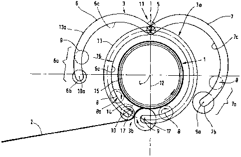
The sole drawing shows a side view of the gripper with the
residual coil.

DETAILED DESCRIPTION OF THE PREFERRED EMBODIMENTS

The residual coil 1 is to be coiled from a residual strip
2. A gripper 3 is used for this purpose to coil the residual
coil 1 at the end of a rolling operation from residual strip 2
running out of a strip mill, such that the gripper can be

pivoted or moved above a strip mill.

The gripper 3 is shown both in its operating position 13
and in its nonoperating position 13a with its gripping arms 6,7
swung out.

6a


CA 02465284 2004-04-28

Besides acting as a discharging device 3a, the gripper 3
additionally acts as a coiling device 3b. The gripper 3 has
gripping arms 6 and 7 that can swing in opposite directions
about an axis of rotation 5 that runs parallel to the axis 4 of

the coiler mandrel. A supporting roller 8 is rotatably
supported on the inner aspect of the end regions 6a and 7a of
each of the gripping arms 6 and 7. A driven roller 9 is
rotatably supported on the end 7b of one of the gripping arms,
and a mating roller 10 is rotatably supported on the opposing
end 6b of the other gripping arm. The supporting rollers 8 are
rotatably supported idler rollers and retain the residual coil
horizontally and vertically.

The mating roller 10 has a smaller diameter than the
associated driven roller 9. The supporting rollers 8, the
driven roller 9 and the mating roller 10 are arranged in such a

way that a swivel hinge 11 for the swiveling gripping arms in
the operating position forms a plane 12 with the coiler mandrel
axis 4. The driven roller 9 is arranged at an angle of 5 to
in front of the plane 12 formed by the coiler mandrel axis 4
and the axis of rotation 5 of the pair of gripping arms 6, 7 in
operating position 13.

7


CA 02465284 2004-04-28

The necessary freedom of the residual strip 2 for the
growing thickness of the residual coil 1 is obtained by
arranging the axis of rotation l0a of the mating roller 10
relative to the driven roller 9 at a distance 14 from the
instantaneous circumference 15 of the residual strip 2 to be
coiled. The distance 14 is further maintained by virtue of the
fact that the axis of rotation 8a of each supporting roller 8 is
pivoted approximately on the inner circumference 6c, 7c of the
respective gripping arm 6 and 7.

The mating roller 10 and the driven roller 9, respectively,
are pivoted with their axes of rotation l0a and 9a approximately
in the middle of the thickness 16 of the respective gripping

arm.

The configuration is further supplemented by pivoting the
mating roller 10 and the driven roller 9 with their axes of
rotation 10a, 9a at the end 6b, 7b of the respective gripping
arm 6 or 7 in an end-center point 17.

8


CA 02465284 2004-04-28

List of reference Numbers
1 residual coil

2 residual strip
3 gripper

3a discharging device
3b coiling device

4 coiler mandrel axis
axis of rotation

6 gripping arm

6a end region of the gripping arm
6b end of gripping arm

6c inner circumference of the gripping arm
7 gripping arm

7a end region of the gripping arm
7b end of gripping arm

7c inner circumference of the gripping arm
8 supporting roller

8a axis of rotation of the supporting roller
9 driven roller

9


CA 02465284 2004-04-28

9a axis of rotation of the driven roller
mating roller

l0a axis of rotation of the mating roller
11 swivel hinge

12 plane of the coiler mandrel axis
13 operating position

13a nonoperating position
14 distance

instantaneous circumference
16 thickness of the gripping arm
17 end-center point


Representative Drawing
A single figure which represents the drawing illustrating the invention.
Administrative Status

For a clearer understanding of the status of the application/patent presented on this page, the site Disclaimer , as well as the definitions for Patent , Administrative Status , Maintenance Fee  and Payment History  should be consulted.

Administrative Status

Title Date
Forecasted Issue Date 2010-02-23
(86) PCT Filing Date 2002-11-09
(87) PCT Publication Date 2003-06-05
(85) National Entry 2004-04-28
Examination Requested 2007-10-05
(45) Issued 2010-02-23
Deemed Expired 2011-11-09

Abandonment History

There is no abandonment history.

Payment History

Fee Type Anniversary Year Due Date Amount Paid Paid Date
Registration of a document - section 124 $100.00 2004-04-28
Application Fee $400.00 2004-04-28
Maintenance Fee - Application - New Act 2 2004-11-09 $100.00 2004-04-28
Maintenance Fee - Application - New Act 3 2005-11-09 $100.00 2005-11-02
Maintenance Fee - Application - New Act 4 2006-11-09 $100.00 2006-10-25
Request for Examination $800.00 2007-10-05
Maintenance Fee - Application - New Act 5 2007-11-09 $200.00 2007-11-06
Maintenance Fee - Application - New Act 6 2008-11-10 $200.00 2008-11-05
Registration of a document - section 124 $100.00 2009-09-09
Maintenance Fee - Application - New Act 7 2009-11-09 $200.00 2009-10-29
Final Fee $300.00 2009-12-10
Owners on Record

Note: Records showing the ownership history in alphabetical order.

Current Owners on Record
SMS SIEMAG AKTIENGESELLSCHAFT
Past Owners on Record
DENKER, WOLFGANG
SCHAEFER, MICHAEL
SMS DEMAG AKTIENGESELLSCHAFT
Past Owners that do not appear in the "Owners on Record" listing will appear in other documentation within the application.
Documents

To view selected files, please enter reCAPTCHA code :


To view images, click a link in the Document Description column. To download the documents, select one or more checkboxes in the first column and then click the "Download Selected in PDF format (Zip Archive)" or the "Download Selected as Single PDF" button.

List of published and non-published patent-specific documents on the CPD .

If you have any difficulty accessing content, you can call the Client Service Centre at 1-866-997-1936 or send them an e-mail at CIPO Client Service Centre.


Document
Description 
Date
(yyyy-mm-dd) 
Number of pages   Size of Image (KB) 
Abstract 2004-04-28 2 79
Claims 2004-04-28 3 79
Drawings 2004-04-28 1 22
Description 2004-04-28 10 266
Representative Drawing 2004-04-28 1 22
Cover Page 2004-06-23 1 45
Claims 2007-10-22 3 66
Description 2007-10-22 11 279
Representative Drawing 2010-01-28 1 15
Cover Page 2010-01-28 1 46
PCT 2004-04-28 7 268
Assignment 2004-04-28 4 132
Correspondence 2004-06-19 1 27
Assignment 2004-07-05 3 91
PCT 2004-04-29 3 108
Prosecution-Amendment 2007-10-05 1 45
Prosecution-Amendment 2007-10-22 8 175
Fees 2007-11-06 1 59
Fees 2008-11-05 1 53
Assignment 2009-09-09 17 779
Correspondence 2009-12-10 1 53