Language selection

Search

Patent 2465290 Summary

Third-party information liability

Some of the information on this Web page has been provided by external sources. The Government of Canada is not responsible for the accuracy, reliability or currency of the information supplied by external sources. Users wishing to rely upon this information should consult directly with the source of the information. Content provided by external sources is not subject to official languages, privacy and accessibility requirements.

Claims and Abstract availability

Any discrepancies in the text and image of the Claims and Abstract are due to differing posting times. Text of the Claims and Abstract are posted:

  • At the time the application is open to public inspection;
  • At the time of issue of the patent (grant).
(12) Patent: (11) CA 2465290
(54) English Title: FURNACE DOORS FOR COILER FURNACES
(54) French Title: PORTES DE FOURNAISE POUR FOURS DE BOBINAGE
Status: Expired and beyond the Period of Reversal
Bibliographic Data
(51) International Patent Classification (IPC):
  • C21D 09/68 (2006.01)
  • C21D 09/56 (2006.01)
(72) Inventors :
  • DOMMEL, WERNER (Germany)
  • FUCHS, WOLFGANG (Germany)
  • BOHN, ANDREAS (Germany)
(73) Owners :
  • SMS SIEMAG AKTIENGESELLSCHAFT
(71) Applicants :
  • SMS SIEMAG AKTIENGESELLSCHAFT (Germany)
(74) Agent: RICHES, MCKENZIE & HERBERT LLP
(74) Associate agent:
(45) Issued: 2010-09-21
(86) PCT Filing Date: 2002-11-20
(87) Open to Public Inspection: 2003-06-12
Examination requested: 2007-10-18
Availability of licence: N/A
Dedicated to the Public: N/A
(25) Language of filing: English

Patent Cooperation Treaty (PCT): Yes
(86) PCT Filing Number: PCT/EP2002/012973
(87) International Publication Number: EP2002012973
(85) National Entry: 2004-04-28

(30) Application Priority Data:
Application No. Country/Territory Date
101 59 717.7 (Germany) 2001-12-05

Abstracts

English Abstract


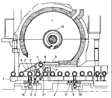
The invention relates to a damper construction (2) of a furnace coiler (1)
which can especially be used in Steckel mills (1). A hot rolled strip is
respectively coiled onto, and uncoiled off, a drum inside the furnace in a
reversing manner, by means of a back and forth transport movement, and is
optionally heated. Guiding flaps (6, 6') are mounted on the displaceable
damper (2) of the furnace coiler, for inserting and guiding the rolled strip.
In order to improve maintenance work, the dampers (2) and the furnace coiler
(1) are embodied as separate components. The dampers (2) are arranged on an
element (4') pertaining to a displaceable roller rack (4), said element being
located beneath the furnace coiler (1). Each damper (2) is divided into at
least two elements (2', 2") which can be hinged together, the two hinged
elements being connected by means of a hinge bearing (7) in a pivoting manner.


French Abstract

La présente invention concerne un structure de registre (2) d'un four de bobinage (1) pouvant être utilisé notamment dans des laminoirs de Steckel. A l'intérieur dudit four, un feuillard laminé à chaud est respectivement enroulé et déroulé de façon réversible sur un rouleau en effectuant un mouvement de va-et-vient, et éventuellement chauffé. Sur le registre (2) en mouvement du four de bobinage sont montés des volets de guidage (6, 6') destinés à charger et à guider le feuillard. Afin d'apporter des améliorations à l'entretien, les registres (2) et le four de bobinage (1) sont des corps séparés. Les registres (2) sont disposés sur une pièce (4') d'un longeron de train de rouleaux mobile (4), située en-dessous du four de bobinage (1). Chaque registre (2) est composé d'au moins deux éléments (2', 2") rabattables l'un par rapport à l'autre et les deux éléments rabattables sont reliés par un palier articulé (7) de façon à pouvoir pivoter.

Claims

Note: Claims are shown in the official language in which they were submitted.


We claim:
1. Furnace doors (2) for coiler furnaces (1) where, as a
hot-rolled strip is being transported back and forth in a
reversing manner through a mill, it is coiled onto a drum
in one of these furnaces and uncoiled from another drum
in the other furnace and possibly heated, the door being
equipped with guide tables (6, 6'), which are mounted on
the furnace doors to feed in and guide a strip, where the
furnace doors (2) and the coiler furnaces (1) are
separate components, each furnace door (2) being movable
and divided into at least two elements (2', 2''), which
are capable of being folded toward and away from each
other, and where the two door elements are connected by a
door support (7) so that they have the freedom to pivot,
wherein the furnace door (2) is mounted on a part (4') of
a roller table frame (4) underneath the coiler furnace
(1), and in that the roller table frame (4) can be moved
along with the furnace door (2) along guide rails (5) and
out of the thermal radiation zone of the coiler furnace
(1).
2. Furnace door according to claim 1, wherein the door
support (7) is mounted on the roller table frame (4) by
brackets (8), one on the drive side, the other on the
operating side.
3. Furnace door according to claim 1, wherein the roller
table frame (4) can be moved by means of one or more
hydraulic cylinders.
4. Furnace door according to claim 1, wherein adjustable
support pads (9) for holding the roller table frame (4)
in an exact position required are mounted underneath the
coiler furnace (1).
11

5. Furnace door according to claim 1, wherein locking
cylinders (10) are provided to lock the roller table
frame (4) in an exact position required underneath the
coiler furnace (1).
6. Furnace door according to claim 1, wherein at least one
hydraulic cylinder, is assigned to each of the pivoting
door elements (2', 2'') of the furnace door (2).
7. Furnace door according to claim 1, wherein the furnace
door (2) is mounted on the brackets (8), and wherein the
door height is adjustable.
8. Furnace door according to claim 6, wherein the at least
one hydraulic cylinder is mounted to an operating side of
each of the pivoting door elements.
9. Furnace door according to any one of claims 1 to 8,
wherein the coiler furnace comprises a Steckel rolling
mill.
12

Description

Note: Descriptions are shown in the official language in which they were submitted.


CA 02465290 2007-11-19
FURNACE DOORS. FOR COILER FURNACES
The invention pertains to furnace doors for coiler
furnaces, suitable especially for use in Steckel rolling mills,
where, as the hot-rolled strip is being transported back and
forth in a reversing manner through the mill, it is coiled onto
a drum in one of these furnaces and uncoiled from another drum
in the other furnace and possibly heated, the door being
equipped with guide tables, which are mounted on the movable
furnace door to feed in and guide the strip, where the furnace
doors and the coiler furnace are separate components, each
furnace door being divided into at least two elements, which can
be folded toward and away from each other, and where the two
door elements are connected by a door support so that they have
the freedom to pivot.
Because of the extremely high thermal loads imposed by the
Steckel furnaces, their adjustable doors have been equipped with
pneumatically actuated drives. The conventional practice has
been to attach these doors directly to the furnace. DE 40 16
256 Al discloses a Steckel furnace of this type. In this case,
1

CA 02465290 2004-04-28
however, it is difficult to replace the guide tables, which are
mounted on the doors. Before the tables can be replaced, the
furnace must be cooled down completely. This requires a
difficult and time-consuming work process, however, not only
because of the very long cooling times but also because of the
extremely difficult working conditions. These circumstances
result in high labor costs and force the system in question to
be idle for long periods of time. DE 40 16 256 Al, however,
also discloses a Steckel furnace of the general type in
question, but it suffers from the same disadvantages.
In view of recognized difficulties, a proposal was
developed as a remedy in EP 0 936 276 A2 to improve the coiler
furnaces used especially in Steckel rolling mills.
The coiler furnace known from the previously mentioned
document comprises an upper housing part and a lower housing
part, which can be tightly connected to each other, and a
furnace drum in the housing with means for accepting a rolled
strip. The housing also has a bottom part, separate from the
lower housing; this bottom part of the housing is able to move
relative to the lower housing. As a result, the bottom part can
be moved even when the interior of the furnace is still hot.
The bottom part is designed and mounted in such a way that it
2

CA 02465290 2004-04-28
can be moved or removed together with the movable roller table
rolls. As a result, the replacement time is reduced from the
previous 30 hours to approximately 5 hours.
Proceeding from the state of the art indicated above, the
invention is based on the task of providing an improved design
for a coiler furnace and especially for its door, by means of
which even shorter replacement times can be achieved.
This task is accomplished for furnace doors of the type
indicated in the introductory clause of Claim 1 in that the
furnace doors and the associated coiler furnace are separate
components; in that the furnace doors are mounted on a part of a
roller table frame located underneath the coiler furnace; and in
that each furnace door is divided into at least two elements,
which can be folded toward and away from each other, the two
door elements being connected to each other by a door support so
that they have the freedom to pivot.
In an embodiment of the invention, it is provided that the
roller table frame is able move along guide rails and thus carry
the furnace door out of the thermal radiation zone of the coiler
furnace.
Attaching the furnace doors to the movable roller table
located underneath the furnace offers the great advantage that
3

CA 02465290 2004-04-28
the furnace doors can be moved out of the thermal radiation zone
of the furnace for the purpose of maintenance. The furnace
tables and the doors can thus be easily maintained. The use of
hydraulic cylinders can also make it easier to operate the doors
and the elements which move them.
An embodiment of the device according to the invention also
provides that the support for the door is mounted on the roller
table frame by way of at least one bracket on the drive side and
at least one bracket on the operating side.
So that the doors can be supported in exactly the right
position under the furnace, the movable part of the roller table
frame is pushed onto adjustable support pads during the
reinstallation process. The exact positioning in the rolling
direction can be achieved by adjusting the frame on the support
pads.
To absorb the forces which develop during the movement of
the strip, the roller table frame is locked in place according
to the invention by locking cylinders.
Additional embodiments provide that at least one hydraulic
cylinder is assigned to each of the pivoting elements of the
furnace door, these cylinders preferably being installed on the
operating side.
4

CA 02465290 2007-11-19
Accordingly, in one aspect, the present invention resides
in furnace doors (2) for coiler furnaces (1) suitable
especially for Steckel rolling mills, where, as the hot-rolled
strip is being transported back and forth in a reversing
manner through the mill, it is coiled onto a drum in one of
these furnaces and uncoiled from another drum in the other
furnace and possibly heated, the door being equipped with
guide tables (6, 6'), which are mounted on the movable furnace
doors to feed in and guide the strip, where the furnace doors
(2) and the coiler furnaces (1) are separate components, each
furnace door (2) being divided into at least two elements (2',
211), which can be folded toward and away from each other, and
where the two door elements are connected by a door support
(7) so that they have the freedom to pivot, wherein the
furnace door (2) is mounted on a part (4') of a roller table
frame (4) underneath the coiler furnace (1), and in that the
roller table frame (4) can be moved along with the furnace
door (2) along guide rails (5) and out of the thermal
radiation zone of the coiler furnace (1).
And finally, the design of the furnace door according to
the invention is characterized in that it is mounted on the
brackets in such a way that its height can be adjusted.

CA 02465290 2007-11-19
BRIEF DESCRIPTION OF THE DRAWINGS
Additional details, features, and advantages of the
invention can be derived from the following explanation of an
exemplary embodiment, which is illustrated schematically in
the drawings:
-- Figure 1 show a cross section of a coiler furnace
along a plane x-x in Figure 4, the furnace being installed
above a roller table, the door being completely closed to
allow the rolled strip to pass freely;
-- Figure 2 shows the coiler furnace according to Figure
1, but with a partially opened door, the forward part of the
door having been lowered to form an angle with the roller
table;
-- Figure 3 shows the coiler furnace according to
Figure 1, but with the door completely open and oriented at an
angle to allow a rolled strip to be fed in and coiled up; and
-- Figure 4 shows a cross section of the roller table
frame along a plane perpendicular to the direction of travel,
with the coiler furnace behind it.
5a

CA 02465290 2004-04-28
Figure 1 shows a longitudinal cross section of a coiler
furnace 1, which can be used especially in Steckel rolling
mills, along the plane x-x in Figure 4. A rolled strip 11 is
uncoiled from a furnace drum 12 in one of these furnaces and
coiled onto another drum in the other furnace in a reversing
manner as it passes back and forth through the rolling stand
situated between them. The coiler furnace holds the rolled
strip at rolling temperature or heats it to the proper
temperature. Guide tables 6, 6' for feeding in and/or guiding
the rolled strip 11 are mounted on separately movable parts 2',
2" of the furnace doors.
The furnace door 2, i.e., the door parts 2', 2'', according
to the invention and the associated coiler furnace 1 are
separate components. These are mounted on a part 4' of the
roller table frame 4 located underneath the coiler furnace 1.
The furnace door can be divided into at least two elements 2',
2'', which can be folded back and forth relative to each other,
and which are for this purpose connected to each other by a door
support, which is designed as a hinge 7, permanently connected
to the part 4' of the roller table frame 4. As a result, it is
6

CA 02465290 2004-04-28
possible to create an opening in the lower part of the housing
of the coiler furnace 1, an opening which greatly improves the
accessibility of the interior of the furnace for the sake of,
for example, repair work or inspection.
In the position of the furnace door 2 according to Figure
1, a finish-rolled hot strip is being removed from the system,
bypassing the coiler furnace and its lower opening. The forward
door part 2' has been raised by the hydraulic cylinder 3' to
form a certain angle, whereas the rear door part 2'' remains in
the horizontal position. The two door parts 2', 2'' are
connected to each other and jointly supported around an axis of
rotation by the door support 7. The hydraulic cylinder 3'' is
assigned to the rear door part 2'', so that this part can also
be pivoted. The door support 7 is itself mounted on the roller
table frame part 4' by at least one bracket 8, 8' on the drive
side and at least one on the operating side (the operating side
is on the left of the plane x-x in Figure 4).
The part 4' of the roller table frame 4 has rollers 14 by
which it can travel out sideways from the roller table frame 4
along rails 5, 5' under the action of one or more hydraulic
7

CA 02465290 2004-04-28
cylinders and thus out of the thermal radiation zone of the
coiler furnace 1, as can be seen in Figure 4. The number 6
designates the guide tables resting on top. Figures 1-4 also
show the motorized furnace drum 12 mounted in the interior of
the coiler furnace 1 and its reel bearings 13, 13'.
The door support 7, the brackets 8 for the door support 7,
and the hydraulic cylinders 3 for the pivoting movement of the
door parts 2, 2' can also be seen in Figure 4. The reference
numbers 9, 9' designate the support pads by which the roller
table part 4' rests on the furnace foundation. The roller table
itself is equipped on its drive and operating sides with the
brackets 8, 8', which serve to accept the door support 7. The
hydraulic cylinders 3, that is, the cylinders 3' and 3'', are
assigned in that order to the furnace door, i.e., to its parts
2', 2'', as can be seen by way of example in Figure 3. The
hydraulic cylinders 3', 3'' are also attached to the roller
table frame part 4' and can be moved sideways together with it
away from the roller table 4 and brought into a maintenance
position. To ensure that the laterally movable elements can be
returned to the exact position required underneath the coiler
8

CA 02465290 2004-04-28
furnace 1, the roller table frame part 4' is pushed onto the
adjustable support pads 9.
As soon as the roller table frame part has been positioned
exactly on the support pads 9, 9' in the rolling direction, the
roller table frame part 4' is locked in place by the locking
cylinders 10, 101.
For the feed-in phase, as Figure 3 shows, the hydraulic
cylinders raise the rear door elements 2', 2'' so that the
arriving rolled strip 11 is lifted to such a level that it can
engage in the feed slot 15 in the furnace drum 12, where it is
gripped and carried along by the drum when the drum starts to
turn.
The inventive design of the coiler furnace doors, which are
attached to the movable roller table, is uncomplicated and
extremely effective and greatly improves the ability to maintain
coiler furnaces.
9

CA 02465290 2004-04-28
List of Reference Numbers
1 coiler furnace
2 furnace door
3 hydraulic cylinder for pivoting
4 roller table frame/roller table frame part
guide rails
6 guide tables
7 door support
8 bracket
9 support pad
locking cylinder
11 rolled strip
12 furnace drum
13 reel support
14 traveling rollers
feed slot

Representative Drawing
A single figure which represents the drawing illustrating the invention.
Administrative Status

2024-08-01:As part of the Next Generation Patents (NGP) transition, the Canadian Patents Database (CPD) now contains a more detailed Event History, which replicates the Event Log of our new back-office solution.

Please note that "Inactive:" events refers to events no longer in use in our new back-office solution.

For a clearer understanding of the status of the application/patent presented on this page, the site Disclaimer , as well as the definitions for Patent , Event History , Maintenance Fee  and Payment History  should be consulted.

Event History

Description Date
Time Limit for Reversal Expired 2015-11-20
Letter Sent 2014-11-20
Grant by Issuance 2010-09-21
Inactive: Cover page published 2010-09-20
Inactive: Final fee received 2010-06-18
Pre-grant 2010-06-18
Notice of Allowance is Issued 2010-04-22
Letter Sent 2010-04-22
Notice of Allowance is Issued 2010-04-22
Inactive: Approved for allowance (AFA) 2010-04-20
Amendment Received - Voluntary Amendment 2010-03-17
Inactive: S.30(2) Rules - Examiner requisition 2010-01-25
Letter Sent 2009-10-26
Amendment Received - Voluntary Amendment 2007-11-19
Letter Sent 2007-11-09
Request for Examination Received 2007-10-18
Request for Examination Requirements Determined Compliant 2007-10-18
All Requirements for Examination Determined Compliant 2007-10-18
Inactive: IPC from MCD 2006-03-12
Letter Sent 2004-08-06
Inactive: IPRP received 2004-07-23
Inactive: Single transfer 2004-07-05
Inactive: Cover page published 2004-06-23
Inactive: Courtesy letter - Evidence 2004-06-22
Inactive: Notice - National entry - No RFE 2004-06-19
Application Received - PCT 2004-05-28
National Entry Requirements Determined Compliant 2004-04-28
Application Published (Open to Public Inspection) 2003-06-12

Abandonment History

There is no abandonment history.

Maintenance Fee

The last payment was received on 2009-10-29

Note : If the full payment has not been received on or before the date indicated, a further fee may be required which may be one of the following

  • the reinstatement fee;
  • the late payment fee; or
  • additional fee to reverse deemed expiry.

Patent fees are adjusted on the 1st of January every year. The amounts above are the current amounts if received by December 31 of the current year.
Please refer to the CIPO Patent Fees web page to see all current fee amounts.

Owners on Record

Note: Records showing the ownership history in alphabetical order.

Current Owners on Record
SMS SIEMAG AKTIENGESELLSCHAFT
Past Owners on Record
ANDREAS BOHN
WERNER DOMMEL
WOLFGANG FUCHS
Past Owners that do not appear in the "Owners on Record" listing will appear in other documentation within the application.
Documents

To view selected files, please enter reCAPTCHA code :


To view images, click a link in the Document Description column. To download the documents, select one or more checkboxes in the first column and then click the "Download Selected in PDF format (Zip Archive)" or the "Download Selected as Single PDF" button.

List of published and non-published patent-specific documents on the CPD .

If you have any difficulty accessing content, you can call the Client Service Centre at 1-866-997-1936 or send them an e-mail at CIPO Client Service Centre.


Document
Description 
Date
(yyyy-mm-dd) 
Number of pages   Size of Image (KB) 
Claims 2004-04-27 2 63
Description 2004-04-27 10 301
Drawings 2004-04-27 4 145
Abstract 2004-04-27 2 101
Representative drawing 2004-04-27 1 55
Description 2007-11-18 11 321
Claims 2007-11-18 2 51
Claims 2010-03-16 2 54
Representative drawing 2010-08-29 1 22
Notice of National Entry 2004-06-18 1 192
Courtesy - Certificate of registration (related document(s)) 2004-08-05 1 105
Reminder - Request for Examination 2007-07-22 1 119
Acknowledgement of Request for Examination 2007-11-08 1 177
Commissioner's Notice - Application Found Allowable 2010-04-21 1 164
Maintenance Fee Notice 2015-01-01 1 170
PCT 2004-04-27 11 453
Correspondence 2004-06-18 1 25
PCT 2004-04-28 3 159
Fees 2008-11-16 1 53
Correspondence 2010-06-17 1 51