Note: Descriptions are shown in the official language in which they were submitted.
CA 02465446 2004-05-10
WO 03/048503 PCT/GB02/05387
TUBING EXPANSION
FIELD OF THE INVENTION
This invention relates to a device for use in tubing
expansion, and also to a method of expanding tubing. In
particular, embodiments of the invention relate to devices
and methods for use in expanding tubing downhole.
BACKGROUND OF THE INVENTION
In the oil and gas exploration and production
industry, bores drilled to access subsurface hydrocarbon-
bearing reservoirs are lined with tubing, known as casing
and liner. Furthermore, strings of tubing may be located
within the cased bore to, for example, carry production
fluid to surface. Recently, there have been numerous
proposals to use tubing which is expanded downhole, that is
:1
tubing of a first diameter is run into a bore and then
expanded to a larger second diameter downhole. This offers
many advantages to the operator, primarily providing the
ability to create lined bores which do not necessarily
suffer a loss in internal diameter each time a string of
tubing is located in the bore, beyond an existing section
of tubing-lined bore.
Early proposals for expanding tubing downhole featured
the use of cones or mandrels, which are driven through the
CA 02465446 2004-05-10
WO 03/048503 PCT/GB02/05387
2
tubing in order to expand the tubing. Other proposals
include the use of roller expanders, which feature
radially-urged rollers. The expanders are rotated within
the tubing, and create a reduction in the wall thickness of
the tubing, with a corresponding increase in diameter.
It is among the objectives of embodiments of the
present invention to provide improved devices and methods
for use in expanding tubing downhole.
SUMMARY OF THE INVENTION
According to a first aspect of the present invention
there is provided a tubing expansion device, the device
being adapted to be advanced axially through tubing to be
expanded and comprising:
a body; and
a plurality of independently radially movable
expansion members mounted on the body.
According to a further aspect of the present invention
there is provided a method of expanding tubing, the method
comprising the steps of:
providing an expansion device comprising a body and a
plurality of independently radially movable expansion
members mounted on the body;
moving the expansion device substantially axially
through tubing to be expanded such that the expansion
members are translated axially relative to the tubing; and
CA 02465446 2004-05-10
WO 03/048503 PCT/GB02/05387
urging the expansion members radially outwards into
contact with an inner wall of the tubing.
The provision of independently movable expansion
members allows devices and methods in accordance with
embodiments of the invention to operate in situations where
it is difficult or impossible to expand tubing to a
uniformly cylindrical configuration, that is the device is
"compliant".- This is in contrast to the situation where an
expansion cone or mandrel is utilised; if an area of the
tubing wall cannot be expanded to the cone diameter, the
cone will be unable to pass, and may indeed become stuck
fast in the tubing. Furthermore, the use of an axially
movable expansion device avoids one of the difficulties
associated with conventional rotary expansion systems,
which apply significant rotational torques to the tubing.
In some cases, the torques may be sufficient to induce
permanent rotational strain in the tubing, particularly in
slotted tubing. The application of significant rotational
torques to tubing strings undergoing expansion also has the
potential to create problems at threaded couplings between
tubing sections.
Preferably, the expansion members are one or both of
axially and circumferentially spaced.
Preferably, the expansion process is carried out
downhole. In this application the ability of the device to
accommodate variations in tubing profile or diameter is
CA 02465446 2004-05-10
WO 03/048503 PCT/GB02/05387
4
particularly useful, as it will often be the case that
downhole tubing, whether in the form of casing or liner
being expanded within a previously unlined 'or open bore, or
a hanger or other tubing form being expanded within a
larger diameter tubing, will encounter irregularities or
restrictions that prevent expansion of the tubing to a
constant diameter uniformly cylindrical configuration.
At least one of the plurality of expansion members may
be radially movable relative to the body; the other of the
expansion members may be radially fixed relative to the
body. For example, three expansion members may be located
at 120 degrees spacing on the body, and if one member is
radially movable the device may still be capable of
accommodating irregular expansion of the tubing. However,
it is preferred that all of the expansion members are
radially movable.
Preferably, at least one of the expansion members is
rotatable, most preferably about an axis which lies
substantially perpendicular to the tubing axis. Most
preferably, a plurality of the expansion members are
rotatable. This configuration of expansion member will
tend to reduce the friction between the expansion members
and the tubing inner wall, reducing the force necessary to
move the device through the tubing and also reducing the
rate of wear experienced by the expansion members. One or
more of the expansion members may be non-rotating, and
CA 02465446 2004-05-10
WO 03/048503 PCT/GB02/05387
provide for a predominantly sliding contact with the tubing
wall. The faces of such members will typically be formed
from a suitable wear-resistant material, such as a ceramic
or a relatively hard metallic compound or alloy, and may be
5 lubricated by well fluid or by fluid or material
specifically provided for its lubrication properties.
In addition to the circumferentially spaced
independently radially movable expansion members, further
expansion members may be provided on the body which are
collectively movable, that is the expansion members are not
independently radially movable, or are non-compliant.
Other expansion members may define a fixed diameter.
Typically, any non-compliant or fixed diameter members will
be located towards a leading end of the expander, and will
be utilised to provide an initial degree of expansion.
The expansion members may be actuated by any
appropriate means, including hydraulic actuation or
mechanical actuation. In other embodiments the expansion
members may be electrically actuated, or may be chemically
or explosively actuated. Conveniently, the expansion
members are mounted on pistons which are located in
appropriate recesses or ports in the body, such that an
elevated pressure within the body urges the piston, and
thus the expansion member, radially outwardly. In other
embodiments, axially movable pistons may be provided, which
pistons act, via cams or the like, on radially movable keys
CA 02465446 2004-05-10
WO 03/048503 PCT/GB02/05387
6
or fingers. Alternatively, the expansion members may be
urged outwardly by springs or other biassing means, or the
members themselves may be flexible or compliant or comprise
flexible or compliant portions.
Preferably, the expansion device is provided in
combination with driving means for applying an axial motive
force to the body. The driving means may be located
remotely of the body, for example where the invention is
being utilised to expand tubing downhole, an arrangement
may be provided on surface for applying weight to a member
on which the device is mounted. Alternatively,, or in
addition, the driving means may be arranged to engage the
tubing in which the device is located. In some
embodiments, the driving means may feature seals for
engaging the tubing inner surface, such that a fluid
pressure differential across the seals creates an axial
force on the device. The seals may be adapted for engaging
the expanded tubing wall, particularly if the unexpanded
tubing wall is non-cylindrical. However, it is preferred
that the seals are adapted for engaging the unexpanded
tubing wall, as this is likely to be of a consistent form;
the invention is primarily intended for use in situations
where there is a possibility that the expanded tubing may
include irregularities. The location of the seals on the
unexpanded tubing, that is in front of or below the device,
also provides the numerous advantages as set out in our
CA 02465446 2006-11-06
7
earlier application W002081863. Briefly, the elevated
fluid pressure surrounding the device may be utilised to
assist in expanding the tubing, and also serves to
lubricate the device.
In other embodiments, the driving means may comprise a
tractor of the like for pushing or pulling the device
through the tubing.
In still further embodiments, the driving means may
comprise an anchor or other gripping arrangement for
engaging the tubing forwardly or rearwardly of the device,
such that the device may then be pulled or pushed through
the tubing relative to the fixed anchor. It is most
preferred that such an anchor is provided forwardly of the
device, such that the device is pulled through the tubing.
This offers the advantage that the tubing form and
dimensions at the anchor location are known, such that the
anchor may be dimensioned appropriately, and it is more
likely that the anchor will be securely and reliably
located in the tubing.
. The driving means may further comprise an arrangement
to provide a hammer or impulse force to the device, or to
vibrate the device. Downhole hammers and shock tools
suitable for this purpose are known to those of skill in
the art, and further arrangements are also disclosed in our
earlier application no. GB0114872.5.
CA 02465446 2006-11-06
8
Of course, the driving means may utilise any number of
different arrangements, for example a combination of weight
applied from surface and fluid pressure, or a combination
of fluid pressure and mechanical force used to draw the
device through tubing towards an anchor. Most preferably,
the anchor is releasable.
The unexpanded tubing may take any appropriate form,
and may have a cylindrical wall, a corrugated generally
cylindrical wall, or.the unexpanded tubing wall may be
folded, such that the expansion process involves, at least
in part, an unfolding of the wall. Thus the expansion of
the tubing may involve one or, both of circumferential
extension of the wall and a re-configuration of the wall.
The tubing may be solid-walled, slotted or perforated,
holed, partially holed, that is with areas of reduced wall
thickness, or indeed may take any form. The tubing may
comprise multiple elements, and may be in the form of a
sand screen or the like.
The tubing will typically be metallic, but may be of
any material or combination of materials appropriate to the
circumstances.
The tubing may be formed of a plurality of tubing
sections, or may be a substantially continuous length, for
example a spoolable or reelable tubing.
The tubing may be located in open hole, or may be
CA 02465446 2006-11-06
9
located within a larger diameter tubing or bore.
Typically, the tubing will be expanded into contact with
the surrounding bore wall or larger diameter tubing.
According to an aspect of the present invention there
is provided a tubing expansion device adapted to be
advanced axially through tubing to be expanded and
comprising:
a body; and
first, second and third actuatable expansion members
mounted on the body, each of the expansion members being
radially movable independently fr-om one another.
According to another aspect of the present invention
there is provided a tubing expansion device adapted to be
advanced axially through tubing to be expanded and
comprising:
a body having a longitudinal axis; and
a plurality of expansion members mounted on the body,
at least one of the expansion members being independently
radially movable and at least one of the expansion members
being rotatable about an axis which lies substantially
perpendicular to the body axis.
According to a further aspect of the present invention
there is provided a method of expanding tubing, the method
comprising the steps of:
providing an expansion device comprising a body and
first, second and third actuatable expansion members
mounted on the body, each of the expansion members being
radially movable independently from one another;
moving the expansion device substantially axially
through tubing to be expanded; and
urging the expansion members radially outwards into
contact with an inner wall of the tubing.
According to a further aspect of the present invention
CA 02465446 2006-11-06
9a
there is provided a method of expanding tubing, the method
comprising the steps of:
providing an expansion device comprising a body and
first, second and third actuatable expansion members
mounted on the body, each of the expansion members being
radially movable independently from one another;
locating the device in tubing to be expanded;
urging the expansion members radially outwards towards
an expansion configuration and into contact with an inner
wall of the tubing;
mounting at least one of the expansion members to
permit independent radially inward movement from the
expansion configuration; and
moving the expansion device substantially axially
through the tubing.
According to a further aspect of the present invention
there is provided a tubing expansion device adapted to be
advanced axially through tubing to be expanded, comprising:
a body having a longitudinal axis; and
a first set of extendable rollers circumferentially
spaced around the body at first angular locations, wherein
at least one roller in the first set of extendable rollers
is independently radially moveable;
a second set of extendable rollers circumferentially
spaced around the body at second angular locations
angularly offset from the first angular locations, the
second set of extendable rollers separated along the
longitudinal axis from the first set of extendable rollers,
wherein at least one roller in the second set of extendable
rollers is independently radially moveable,
wherein each roller in the first and second sets of
extendable rollers is rotatable about an axis which lies
substantially perpendicular to the longitudinal axis of the
CA 02465446 2006-11-06
9b
body.
According to a further aspect of the present invention
there is provided a tubing expansion device adapted to be
advanced axially through tubing to be expanded and
comprising:
a body having a longitudinal axis; and
first, second and third expansion members mounted on
the body, each of the expansion members being radially
movable independently from one another, at least one of the
expansion members being rotatable about an axis which lies
substantially perpendicular to the body axis. -
These and other aspects of the present invention will
now be described, by way of example, with reference to the
accompanying drawings, in which:
Figure 1 is a diagrammatic illustration of expanded
tubing;
Figure 2 is a perspective view of a tubing expansion
device in accordance with a preferred embodiment of the
present invention;
Figure 3 is.a sectional view of Figure 2;
Figures 4 and 5 are part-cut away illustrations of
tubing expansion devices in accordance with a further
embodiment of the present invention; and
Figure 6 is a perspective view of a tubing expansion
device in accordance with a still further embodiment of the
present invention, shown in use.
Reference is first made to Figure 1 of the drawings,
which illustrates a section of downhole tubing 10 which has
CA 02465446 2006-11-06
9c
been expanded by a tubing expansion device in accordance
with an embodiment of the present invention, as will be
described. The tubing 10 was originally of diameter dl.
However, an expansion device has been run through the
tubing 10, with the aim'of expanding the tubing to a larger
diameter d,. This expansion has brought the outer wall of
CA 02465446 2004-05-10
WO 03/048503 PCT/GB02/05387
the tubing 10 into contact with the surrounding open bore
wall. However, in one section of the tubing 10 a
restriction 12 around the tubing has prevented the
expansion of the tubing 10 to diameter d2, and the tubing
5 has only been expanded to a smaller diameter di.
With many conventional expansion devices, such as
expansion cones or mandrels, expansion of the tubing beyond
the restriction 12 would not be possible, as the diameter
of the cone is fixed and the cone would simply be unable to
10 expand the tubing and progress through the restriction 12.
In practice, it is likely that the cone will become stuck
at the restriction 12. However, as will be described, by
utilising expansion devices in accordance with embodiments
of the invention, it is possible to accommodate such
restrictions 12.
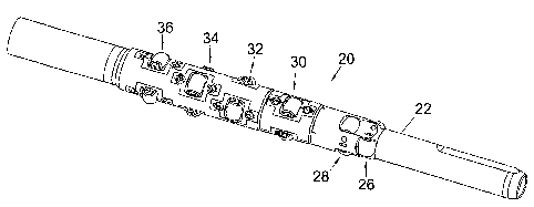
Reference will now also be made to Figures 2 and 3 of
the drawings, which illustrate a tubing expansion device 20
in accordance with a preferred embodiment of the present
invention. The device 20 comprises a generally cylindrical
tubular body 22 adapted for mounting to a support string
(not shown) A bore 24 extends through the body 22 to
allow fluid to be transmitted therethrough.
At least one roller is mounted in the body 22, and in
the preferred illustrated embodiment there are five sets of
rollers, each roller with its axis of rotation
perpendicular to the main axis of the body 22. Each set of
CA 02465446 2004-05-10
WO 03/048503 PCT/GB02/05387
11
rollers has at least one roller, and in the preferred
illustrated embodiment there are three angularly spaced
rollers; in this embodiment the rollers are at 120' angular
spacings, although other spacings. may be adopted if
desired. The first and second sets of rollers 26, 28 may
be radially fixed, that is the rollers 26, 28 describe a
fixed radius. However, the rollers in each of the third,
fourth, fifth and sixth sets 30, 32, 34, 36 may be radially
movable. In particular, each roller may be mounted on a
piston 40 located within a respective radial body recess
42. Each recess 42 is in fluid communication with the body
bore 24, such that an elevated fluid pressure within the
bore 24 urges the rollers radially outwardly.
In use, the device 20 may be advanced through tubing
to be expanded by one of a number of means including
application of weight from surface, or use of an anchor
located ahead of the device 20, against which the device 20
is pulled through the tubing 10. The fixed radius rollers
26, 28 are dimensioned to describe a diameter slightly
larger than dl, such that the rollers 26, 28 will provide an
initial degree of expansion of the tubing 10. Further
expansion will be provided by the other sets of rollers 30,
32, 34, 36 which, when actuated, describe a larger, maximum
diameter and are capable of expanding the tubing 10 to
diameter d,.
On encountering a restriction 12, which prevents the
CA 02465446 2004-05-10
WO 03/048503 PCT/GB02/05387
12
tubing 10 from being expanded to diameter d2, the first and
second sets of rollers 26, 28 will provide an initial
relatively small degree of expansion which will not be
affected by the restriction 12. However, on the other
rollers 30, 32, 34, 36 encountering the restriction, the
tubing 10 will be expanded to the maximum extent permitted
by the restriction 12. The rollers 30, 32, 34, 36 will
normally operate at their greatest radial extension,
corresponding to diameter d,. However, where this is not
possible, such as when prevented by the restriction 12, the
rollers and their respective pistons will simply be forced
radially inwardly relative to the body 22 by the tubing
wall. Thus, the rollers 30, 32, 34 will expand the tubing
10 to the maximum extent permitted by the restriction and
will still be able to pass through the resulting
restriction in the expanded tubing diameter.
Figure 1 illustrates a restriction in the expanded
tubing in the form of a necking of the tubing 10, however
as each roller is mounted on a respective independently
movable piston., the device 20 will also accommodate a
restriction which occurs at only one portion of the
circumference.
Reference is now made to Figures 4 and 5 of the
drawings, which illustrate a tubing expansion device 50 in
accordance with a further embodiment of the present
invention. In this example, the device 50 features a
CA 02465446 2004-05-10
WO 03/048503 PCT/GB02/05387
13
tubular body 52 carrying a leading fixed diameter swage 54
for inducing an initial degree of expansion, in a similar
manner to the first and second roller sets 26, 28 described
above. Following the fixed swage 54 are circumferentially
spaced fingers 56. In this embodiment four fingers 56 are
provided and are each mounted on a respective pivot pin 58,
the axis of each pin 58 being perpendicular to the body
axis. The fingers 56 are biassed radially outward, and in
normal circumstances will expand the tubing 10 to the
diameter d,. However, on encountering a restriction 12,
the fingers 56 may be forced inwardly, such that the device
50 extends the tubing'to the intermediate diameter d3 and
may pass through and beyond the restriction 12.
Reference is now made to Figure 6 of the drawings,
which illustrate a tubing expansion device 100 in
accordance with a still further embodiment of the present
invention. The device 100 is illustrated located within a
section of liner 102 which the device is being used to
expand, the illustrated section of liner 102 being located
within a section of cemented casing 104; the device 100 is
being utilised to create a liner hanger.
In this example, the device 100 features a central
mandrel 106 carrying a leading sealing member in the form
of a swab cup 108, and an expansion cone 110. The swab cup
108 is dimensioned to provide a sliding sealing contact
with the inner surface of the liner 102, such that elevated
CA 02465446 2004-05-10
WO 03/048503 PCT/GB02/05387
14
fluid pressure above the swab cup 108 tends to move the
device 100 axially through the liner 102. Furthermore, the
elevated fluid pressure also assists in the expansion of
the liner 102, in combination with the mechanical expansion
provided by the contact between the cone 110 and the liner
102.
The cone 110 is dimensioned and shaped to provide a
diametric expansion of the liner 102 to a predetermined
larger diameter as the cone 110 is forced through the liner
102. However, in contrast to conventional fixed diameter
expansion cones, the cone 110 is at least semi-compliant,
that is the cone 110 may be deformed or deflected to
describe a slightly smaller diameter, or a non-circular
form, in the event that the cone 110 encounters a
restriction which prevents expansion of the liner 102 to
the desired larger diameter cylindrical form. This is
achieved by providing the cone 110 with a hollow annular
body 112, and cutting the body 112 with angled slots 114 to
define a number, in this example six, deflectable expansion
members or fingers 116. Of course the fingers 116 are
relatively stiff, to ensure a predictable degree of
expansion, but may be deflected radially inwardly on
encountering an immovable obstruction.
The slots 114 may be filled with a deformable
material, typically an elastomer, or may be left free of
material.
CA 02465446 2004-05-10
WO 03/048503 PCT/GB02/05387
The device 100 may also include a leading fixed
diameter swage (not shown) for inducing an initial degree
of expansion, and furthermore serving to stabilise the cone
110.
5 It will be apparent to those of skill in the art that
the above-described devices provide a convenient and
effective means for expanding tubing downhole, and are
particularly useful for applications where the ability to
expand the tubing to a uniform cylindrical form cannot be
10 assured.
Those of skill in the art will also recognise that
these embodiments are merely exemplary of the present
invention, and that various'modifications and improvements
may be made thereto, without departing from the scope of
15 the present invention.