Note: Descriptions are shown in the official language in which they were submitted.
CA 02465541 2009-11-06
VARIABLE FUNCTION PERSON TRANSPORTATION SYSTEM(S)
The present invention relates to load (e.g. person) transportation systems. It
in particular relates to
load (e.g. person) transportation systems which comprise one or more motorized
units which are
energized, for example by one or more electrical batteries, the systems
including energy stations for
the recharge of any such batteries. The present invention more particularly
relates to a patient-
handling system or apparatus which gives an operator the possibility of
choosing between a manual or
a motorised horizontal displacement of a person, e.g. of a (non-ambulatory)
patient.
Support structures are known for lifting and transferring loads as well as
people; please see for
example U.S. patent nos. 5,809,591, 5,694,654, 5,337,908 and 3,000,329; please
also see for example
U.S. patent no. 6085368, the entire contents of which is hereby incorporated
by reference, which
relates to a winch assembly for such a person handling system. It is known for
example to exploit
adjustable mast or pole support structures for use with overhead rails or
tracks for forming support
structures or frames (see for example U.S. Patent no 3,000,329 and 2,630,076).
It is in particular known to use an overhead track or track system as part of
a people displacement
device or system.. Such a track or track system may be directly bolted or
otherwise fixed to the
ceiling of a room. Alternatively such a track or track system may be
maintained in place by a mast,
pole or support rod assembly(ies). These structures may thus be intended to be
more or less
permanent fixtures or may be structures which may be able to be easily taken
apart for the purpose of
being rebuilt at some other location.
The present invention will be discussed herein after, in particular, with
respect to a device(s) or
system(s) for displacing (e.g. lifting, transporting, lowering, etc.) a person
between various positions
or areas such as for example between a bed and a chair, a bed and a bathroom
etc.. The clutch devices
or assemblies of the present invention may of course be used for the
displacement of any other type of
load.
There is a continuing need for structures for supporting a person and in
particular for a rail or track
support structure or frame which can be used to raise, displace and lower a
(e.g. incapacitated) person.
Such support structures may be needed in many types of environments such as,
for example, in
private homes, hospitals, rehabilitation centres, group homes for the aged,
etc. Such structures may,
for example, be used to facilitate the transfer a bed ridden person from a bed
to a wheel chair, to a
bath tub or the like. Examples of lift devices are disclosed in U.S. patent
nos, 3,877,421, 5,379,468
and 5,649,329.
CA 02465541 2009-11-06
It is known to provide a person handling system comprising a winch mechanism
associated with a
support rail or track, the support rail being attached or disposed adjacent to
a ceiling. The winch
mechanism may, for example, be attached or connected to the rail or track via
a carriage (or a trolley)
component. A trolley electric motor may be provided for inducing displacement
of the carriage
component along the rail. Such systems may also include one or more recharging
station for the
recharge of motor battery(ies) as well as means for (automatically) inducing
the winch mechanism to
travel to and electrically engage the recharging station for recharge of the
battery(ies).
A drawback of such motor induced displacement of the carriage is that the
displacement may be preset
at a relatively slow predetermined speed (i.e. for safety reason). However,
occasions may arise when
an operator may wish for a more speedy displacement of the winch mechanism;
such more speedy
displacement may be necessary or desired if for some reason the winch
mechanism itself is
obstructing, hampering or delaying some desired or necessary activity. For
example, a difficulty with
the automatic return to the charging station is that the displacement of the
carriage along a rail and the
to the charging station may also be relatively slow in relation to the desired
speed with which such
displacement may be desired.
Accordingly, it would be advantageous to have a relatively flexible handling
system which could offer
the operator the choice between a motorized displacement and a manual
displacement of the winch
assembly. The speed of displacement, in the case of a manual displacement, may
be higher than the
speed that is possible under influence of the motor function.
It is also known to have a winch assembly which does not have a trolley motor
or the like for
2
Printed: 02-02-2004; DESCPAM D CA0201505
displacing the winch assembly along the a rail. In this case, since the winch
assembly is not associated
with a trolley motor, the winch assembly must be manually dragged from one
point on the rail to
another, i.e. to a recharge station.
Thus, from the above it may be appreciated that at present, it is known to
provide, a person transport
system which has a winch assembly which is displaceable horizontally along a
support either manually or
under the influence of an (electric) motor (but not both).
It would be advantageous to be able to have a single winch system which could
provide both a. Motorized
as well as non motorized displacement function i.e. to allow for a motorized
displacement of the winch
system along the carriage track or rail or, if desired, a manual displacement
of the winch assembly along
the carriage track. Such a winch assembly would have a beneficial effect in
relation to production as
well as storage since it would no longer be necessary to supply two distinct
types of winch assemblies i.e.
one with a motorized function and one with a manual function. A dual function
system as described
would thus facilitate production and storage since a single type of assembly
could be used in either
circumstances depending upon the desires of the user, i.e. only one type of
assembly need be made.
In any event, it would be advantageous to have a mechanism whereby the motor
and/or the mechanism
which induces displacement of the winch assembly may be decoupled from the
carriage track i.e. for
example for the electric motor to be decoupled from drive wheels which induced
displacement of the
winch assembly along the rail. In this latter case, it would be advantageous
to have a clutch system
which would provide an engagement state whereby the motor would induce such
displacement along the
rail and a non engagement state which would allow manual displacement of the
winch assembly along
the rail. It would also be advantageous to have a simple quick mechanism which
could bring about such
coupling and decoupling.
STATEMENT OF INVENTION
In accordance with an aspect the present invention provides a carriage
assembly comprising
a) a carriage component, said carriage component being configured for coupling
to a carriage track of an
overhead support for displacement thereof along said carriage track
and
b) a (carriage) displacement component for inducing displacement of said
carriage component along said
3
EP0_Dr,1
L+ ~iI
1 7 09. 20013
CA 02465541 2004-04-30
1" 17-09-2003
CA 02465541 2009-11-06
carriage track,
said (carriage) displacement component comprising an electric motor element
and a clutch coupling
element
said electric motor element being configured for providing driving effort for
the displacement of said
carriage component along said carriage track
said clutch coupling element being configured for coupling and de-coupling the
driving effort of said
electric motor element (i.e. relative to a track or rail) such that
when the driving effort of said electric motor element is coupled and said
electric motor
element is energised said carriage component may be urged along said carriage
track by said electric
motor element and
when the driving effort of said electric motor element is de-coupled said
carriage component
may be manually displaced along said carriage track.
The present invention in particular provides a person handling system carriage
assembly, said
carriage assembly comprising
a) a carriage component, said carriage component comprising a wheel element
configured for
coupling said carriage component to a carriage track of an overhead support
for displacement thereof
along said carriage track
and
b) a (carriage) displacement component for inducing displacement of said
carriage component along
said carriage track,
said (carriage) displacement component comprising an electric motor element
and a clutch coupling
element
said clutch coupling element being configured for coupling and de-coupling
said electric motor
element and said wheel element such that
when said electric motor element and said wheel element are coupled and said
electric motor
element is energised said carriage component may be urged along said carriage
track by said electric
motor element and
when said electric motor element and said wheel element are de-coupled said
carriage
component may be manually displaced along said carriage track.
In accordance with the present invention a carriage assembly may further
include means for
connecting said carriage component to a second support track disposed
transversely to said carriage
track.
4
Printed: 02-02-2004, DESCPAM D CA0201505
In accordance with another aspect the present invention provides a load
handling system or assembly
(e.g. a person handling system or assembly) comprising
a) an overhead support component comprising a carriage track (or rail)
b) a carriage component coupled to said carriage track for displacement
thereof along said carriage track
c) a person lowering and raising winch component attached to said carriage
component
and
d) a (carriage) displacement component for inducing displacement of said
carriage component along said
carriage track,
said (carriage) displacement component comprising a clutch coupling element
and an electric motor
element
said electric motor element being configured for providing driving effort for
the displacement of said
carriage component along said carriage track
said clutch coupling element being configured for coupling and de-coupling the
driving effort of said
electric motor element (i.e. relative to a track or rail) such that
when the driving effort of said electric motor element is coupled and said
electric motor element
is energised said carriage component may be urged along said carriage track by
said electric motor
element and
when the driving effort of said electric motor element is de-coupled said
carriage component
may be manually displaced (e.g. hand dragged) along said carriage track.
The present invention in particular provides a load handling system or
assembly (e.g. a person handling
system or assembly) comprising
a) an overhead support component comprising a carriage track (or rail)
b) a carriage component coupled to said carriage track for displacement
thereof along said carriage track
c) a person lowering and raising winch component attached to said carriage
component
and
d) a (carriage) displacement component for inducing displacement of said
carriage component along said
carriage track or rail,
said (carriage) displacement component comprising an electric motor element
and a clutch coupling
element
said clutch coupling element being configured for coupling and de-coupling
said electric motor element
and said carriage component such that
5
CA 02465541 2004-04-30
3 17-09-2003
Printed 02 02-2004 DESCPAMD CA0201505
when said electric motor and said carriage component are coupled and said
motor is energised
said carriage component may be urged along said carriage track by said motor
and
when said electric motor and said carriage component are de-coupled said
carriage component
may be manually displaced (e.g. hand dragged) along said track.
In accordance with the present invention a person handling system as described
herein may for example
further comprise rechargeable battery means for energising the motor and
battery recharge station means.
A person handling system as described herein may, for example, comprise means
for automatically
bringing the rechargeable battery means into electrical connection with the
battery recharge station.
Alternatively, instead of a battery energisable system, the motor(s) and the
like may if desired be
connected directly to a power outlet means (e.g. wall electrical outlet) by
any suitable electrical
connection mechanism (e.g. sliding contact(s), coiled electrical leads or
wires, etc.). A system may of
course be a hybrid system comprising one or more battery energisable elements
and one or more directly
connected energisable elements
In accordance with a further aspect the present invention provides a winch
assembly comprising
a) a person lowering and raising winch component attached to a carriage
component, said carriage
component being configured for coupling to a carriage track of an overhead
support for displacement
thereof along said carriage track
and
b) a (carriage) displacement component for inducing displacement of said
carriage component along said
carriage track,
said (carriage) displacement component comprising an electric motor element
and a clutch coupling
element
said electric motor element being configured for providing driving effort for
the displacement of said
carriage component along said carriage track
said clutch coupling element being configured for coupling and de-coupling the
driving effort of said
electric motor element (i.e. relative to a track or rail) such that
when the driving effort of said electric motor element is coupled and said
electric motor element
is energised said carriage component may be urged along said carriage track by
said electric motor
element and
when the driving effort of said electric motor element is de-coupled said
carriage component
6
CA 02465541 2004-04-30
4 17092003
rinted: Q2-02-2004 DESCPAMD CA0201505
may be manually displaced along said carriage track.
In accordance with the above further aspect the present invention in
particular provides a winch
assembly comprising
a) a person lowering and raising winch component attached to a carnage
component, said carriage
component being configured for coupling to a track of an overhead support for
displacement thereof
along said track
and
b) a (carriage) displacement component for inducing displacement of said
carriage component along said
track or rail,
said (carriage) displacement component comprising an electric motor element
and a clutch coupling
element
said clutch coupling element being configured for coupling and de-coupling
said electric motor and said
carriage component such that
when said electric motor and said carriage component are coupled and said
motor is energised
said carriage component may be urged along said track by said motor and
when said electric motor and said carriage component are de-coupled said
trolley component
may be manually displaced along said track.
In accordance with the present invention an assembly as described herein may
further comprise
rechargeable battery means for energising the motor.
In an additional aspect the present invention provides a kit comprising
a) an overhead support component comprising at least a carriage track
and
b) an assembly as defined herein (i.e. a winch or carriage assembly).
In accordance with the present invention a kit as described herein may further
comprise rechargeable
battery means for energising the electrical motor element and battery recharge
station means. A kit in
accordance with the present invention may of course comprise one or more other
elements, components,
members, etc. as discussed herein
7
5 CA 02465541 2004-04-30 1 09-2003
CA 02465541 2009-11-06
In an additional aspect the present invention provides a person handling
system comprising
a) an overhead support component comprising a carriage track and two spaced
apart secondary tracks
disposed transversely with respect to said carriage track,
b) a first carriage component coupled to said carriage track for displacement
thereof along said carriage
track
c) second and third carriage components, each of said second and third
carriage components being
coupled to a respective secondary track for displacement thereof along said
respective secondary track,
said carriage track being attached to said second and third carriage
components
d) a person lowering and raising winch component attached to said first
carriage component
e) a first (carriage) displacement component for inducing displacement of said
first carriage component
along said carriage track,
f) a second (carriage) displacement component for inducing displacement of one
of said second and third
carriage components along said respective secondary carriage track,
each of said (carriage) displacement components comprising a respective clutch
coupling element and a
respective electric motor element
each of said respective electric motor elements being configured for providing
driving effort for the
displacement of a respective carriage component along a respective track
each of said respective clutch coupling elements being configured for coupling
and de-coupling the
driving effort of a respective electric motor element (i.e. relative to a
track or rail) such that
when the driving effort of said respective electric motor element is coupled
and said respective
electric motor element is energised said respective carriage component may be
urged along said
respective track by said respective electric motor element and
when the driving effort of said respective electric motor element is de-
coupled said respective
carriage component may be manually displaced along said carriage track.
The present invention in particular provides a person handling system
comprising
a) an overhead support component comprising a carriage track and two spaced
apart secondary tracks
disposed transversely with respect to said carriage track,
b) a first carriage component coupled to said carriage track for displacement
thereof along said carriage
track
c) second and third carriage components, each of said second and third
carriage components being
coupled to a respective secondary track for displacement thereof along said
respective secondary track,
8
CA 02465541 2009-11-06
said carriage track being attached to said second and third carriage
components
d) a person lowering and raising winch component attached to said first
carriage component
e) a first (carriage) displacement component for inducing displacement of said
first carriage component
along said carriage track,
f) a second (carriage) displacement component for inducing displacement of one
of said second and third
carriage components along said respective secondary carriage track,
each of said (carriage) displacement components comprising a respective
electric motor element and a
respective clutch coupling element
each of said respective clutch coupling elements being configured for coupling
and de-coupling a
respective electric motor element and a respective carriage component such
that
when said respective electric motor element and said respective carriage
component are coupled
and said respective electric motor element is energised said respective
carriage component may be urged
along a respective track by said respective electric motor element and
when said respective electric motor element and said respective carriage
component are de-
coupled said respective carriage component may be manually displaced along
said respective track.
The present invention in another aspect provides a person handling system
comprising
a) an overhead support component comprising a carriage track and two spaced
apart secondary tracks
disposed transversely with respect to said carriage track,
b) a first carriage component coupled to said carriage track for displacement
thereof along said carriage
track
c) second and third carriage components, each of said second and third
carriage components being
coupled to a respective secondary track for displacement thereof along said
respective secondary track,
said carriage track being attached to said second and third carriage
components
d) a person lowering and raising winch component attached to said first
carriage component (in this case
the winch component may be solely manually displaceable, solely motor
displaceable or offer the choice
between such displacements as discussed herein)
e) a (carriage) displacement component for inducing displacement of one of
said second and third
carriage components along said respective secondary track,
said (carriage) displacement component comprising a clutch coupling element
and an electric motor
element
said electric motor element being configured for providing driving effort for
the displacement of said
9
CA 02465541 2009-11-06
respective carriage component along a respective track
said respective clutch coupling element being configured for coupling and de-
coupling the driving effort
of said electric motor element such that
when the driving effort of said electric motor element is coupled and said
electric motor element
is energised said respective carriage component may be urged along said
respective track by said electric
motor element and
when the driving effort of said electric motor element is de-coupled said
respective carriage
component may be manually displaced along said carriage track.
The present invention in particular provides a person handling system
comprising
a) an overhead support component comprising a carriage track and two spaced
apart secondary tracks
disposed transversely with respect to said carriage track,
b) a first carriage component coupled to said carriage track for displacement
thereof along said carriage
track
c) second and third carriage components, each of said second and third
carriage components being
coupled to a respective secondary track for displacement thereof along said
respective secondary track,
said carriage track being attached to said second and third carriage
components
d) a person lowering and raising winch component attached to said first
carriage component (in this case
also the winch component may be solely manually displaceable, solely motor
displaceable or offer the
choice between such displacements as discussed herein)
e) a (carriage) displacement component for inducing displacement of one of
said second and third
carriage components along said respective secondary track,
said (carriage) displacement component comprising an electric motor element
and a clutch coupling
element
said clutch coupling element being configured for coupling and de-coupling
said electric motor element
and a respective carriage component such that
when said electric motor element and said respective carriage component are
coupled and said
electric motor element is energised said respective carriage component may be
urged along a respective
track by said electric motor element and
when said electric motor element and said respective carriage component are de-
coupled said
respective carriage component may be manually displaced along said respective
track.
CA 02465541 2009-11-06
An overhead support component may take on any desired or necessary
configuration. The overhead
support component may for example comprise one or more track or rail elements
held in place adjacent a
ceiling by any suitable support means such as for example support poles which
at their distal end engages
a floor; the support means may alternatively take the form of bracket means
attached to the ceiling on the
on hand and to the track or rail on the other.
The overhead support component and the carriage component may be configured
such that said carriage
component engages said track such that the carriage component is able to roll,
slide glide or be otherwise
displaced along said track.
A carriage or trolley component may take on any suitable form which allows it
to be supported by and
glide or be displaced along a track element, i.e. such that a carriage or
trolley component may be moved
manually along the track or may be so moved by providing a suitable motorised
trolley or (carriage)
displacement system. The carriage or trolley component may comprise a wheeled
carriage, i.e. a carriage
component may comprise a wheel element. Alternatively the carriage component
need not be wheeled,
i.e. it may comprise sliding members of a more or less frictionless material
such as of TEFLON.
A clutch coupling element of the (carriage) displacement component, may take
any desired or necessary
configuration keeping in mind its intended purpose, i.e. to be able to control
(i.e. turn on or off) the
application of the transfer of a driving effort from the motor element for the
displacement of the carriage
component relative to the carriage rail or track; for example, for turning on
or off the application of the
transfer of a driving effort from the motor element to the wheel(s) of a
carriage component. Thus the
clutch coupling element may be configured in any suitable manner whereby the
clutch coupling element
is able to couple and de-couple the electric motor and any type of driven
member forming part of the
clutch coupling element. The driven member for its part is of course to be
configured to induce
displacement of the carriage component along the carriage support rail or
track. The driven member
itself may be coupled, for example, directly to the carriage component (i.e.
to a wheel thereof) or be
indirectly coupled thereto in any suitable manner (e.g. via the rail or track
itself). The clutch coupling
element may be configured in any suitable manner such as for example as
specifically discussed herein
(including any mechanical equivalent thereof) The clutch component may for
example comprise a pair
of gear elements which may as desired be engaged or disengaged as the case may
be. The gear elements
may take any desired or necessary form keeping the above in mind. Example of
various types of
clutches are described in the following patents; these may be configured as
necessary or desired for
11
CA 02465541 2009-11-06
exploitation in the context of the present invention; see U.S. patent nos.
6,085,368 4,458,795
3,721,324 3,643,770 2,905,294 2,024,947 and 1,951,139 (the entire contents of
each of which is
incorporated herein by reference).
In accordance with another aspect the present invention in particular provides
a coupling/de-coupling
clutch mechanism or assembly (e.g. reversible mechanism) which may for
example, comprise
a drive shaft able to be (i.e. configured to be) rotated in a first direction
and, if so desired or
necessary, in a second opposite direction (e.g. rotation being induced by an
electric motor to
which the drive is directly or indirectly coupled)
a rotatable driving member coupled to said drive shaft such that rotation of
the drive shaft induces
(a like) rotation of the rotatable driving member
a rotatable driven member (e.g. coupled to a wheel element) for urging a
carriage component
along a track
a clutch member for coupling (i.e. engaging) and decoupling (i.e. disengaging)
said driving
member with said driven member in response to rotation of said drive shaft
(i.e. in said one first
direction and/or said second direction)
said clutch member being configured to couple said driving member with said
driven member for urging
the driven member to rotate in said first direction for urging the carriage
component along the carriage
track and, if so desired or necessary, said clutch component being further
configured to couple said
driving member with said driven member for urging the driven member to rotate
in said second direction
opposite to said first direction for urging the carriage component in an
opposite direction along said
carriage track. The clutch mechanism may comprise means for engaging and
disengaging said clutch
member in response to rotation of said drive shaft.
A clutch mechanism in accordance with the present invention may for example
comprise
a first clutch component configured to couple said driving member with said
driven member for
urging the driven member to rotate in one direction
a second clutch component configured to couple said driving member with said
driven member
for urging the driven member to rotate in a second direction opposite to said
one direction
a means for engaging said first clutch and disengaging said second clutch in
response to rotation
of said drive shaft in said one direction and
a means for engaging said second clutch and disengaging said first clutch in
response to rotation
of said drive shaft in said second direction.
12
CA 02465541 2009-11-06
The above first and second clutch components may for example be comprised in a
single component such
as, for example, a shuttle component as described herein; the first and second
clutch components may of
course take any other (suitable, desired or known) form keeping in mind the
function thereof.
In accordance with the present invention the driving member and the driven
member may be disposed
coaxially relative to the axis of rotation of the drive shaft.
In accordance with the present invention the rotatable driven member may
define an annular or ring
member. The annular or ring member may be provided with any suitable
engagement means or
elements; such engagement means may take the form, for example, of internally
extending sprocket or
gear teeth or alternatively, a plurality of perforations configured for
engagement with engagement means
or elements of the shuttle component as shall be discussed herein
In accordance with the present invention the rotatable driving member may
define a slot (or the like)
extending transversely (i.e. radially) to the axis of rotation of the drive
shaft. The slot may accommodate
a shuttle component which slidingly engages the wall elements of the driving
member defining the slot
such that the shuttle component is able to be displaced to and fro in the slot
transversely to the axis of
rotation of the drive shaft ; the shuttle component
13
CA 02465541 2004-04-30
WO 03/037239 PCT/CA02/01505
is in any event engaged or mounted in the slot such that rotation of the
driving member
induces a like rotation of the shuttle component.
The opposed ends of the shuttle component may be provided with any suitable
(corresponding) engagement means configured for mating engagement or meshing
with the
engagement means or elements of the abovementioned annular or ring member;
such
engagement means may take the form for example of corresponding externally or
outwardly
extending sprocket or gear teeth for mating engagement or meshing with the
internally or
inwardly extending sprocket. or gear teeth of the ring member.
The shuttle component as described herein may, for example, comprise a single
unitary
member; alternatively a shuttle component may for example comprise a pair of
separate
(opposed) slide members. The shuttle component (as well as the displacement
element or
member mentioned below) may be configured such that displacement of the
shuttle component
for engagement with the annular or ring member may be such as to provide a
reversible type of
driving effort (i.e. a driving effort alternatively in either the first or the
second rotational
direction) or a unidirectional driving effort (i.e. a driving effort in one
(e.g. rotational )
direction).
In accordance with the present invention the means for engaging and
disengaging the clutch
may for example comprise a displacement element or member mounted on the drive
shaft.
The displacement element or member may, for example be configured to engage a
projection
extending axially from the shuttle component so as to induce displacement of
the shuttle in the
slot of the driving member in response to a rotational movement of said drive
shaft. In other
words, the displacement element or member may be configured so that in
response to a
rotational movement of the drive shaft, the displacement element or member is
able to engage
the shuttle component so as to induce the shuttle component to alternately
extend from and/or
retract into said slot and thus into engagement or disengagement with the
annular or ring
member (e.g. by the intermeshing of gear teeth). In accordance with the
present invention
means may be provided with a winch assembly which may be configured such that
when
motorised movement of the carriage is no longer desired the motor may be
induced to rotate in
the opposite direction for example a quarter (1/4) turn so as to bring about
disengagement of
the shuttle component for manual displacement of the carriage..
As mentioned above, in accordance with the present invention the electric
motor and the
14
CA 02465541 2009-11-06
driven member (i.e. the member coupled for example to the wheels of a trolley
or carriage as described
herein) may be coupled such that when the motor is energised the carriage may
be displaced along a
track.
A winch assembly (i.e. comprising the rail movement motor, the rail movement
clutch coupling
component, etc.) may, for example, be appropriately configured in any suitable
(known) manner such
that the motor induced rotation of the driven member in one direction leads to
the movement of the
carriage and winch assembly attached thereto in a predetermined direction
along a track whereas
motor induced rotation of the driven member in the opposite direction leads to
movement in the
opposite direction; in this case the clutch is of course to be configured so
as to be reversible with the
driven member.
The motor may be any suitable or desired (known) type of electric motor; if
desired, it may be a
variable speed motor, a reversible motor, a non-reversible motor, etc. The
motor may if desired or as
necessary be associated with other mechanical/electrical elements (e.g. gear
reduction elements,
rotational speed variation means, gear means for changing the direction of
rotation of the worm gear
drive shaft, etc.).
As mentioned above, a motorized version of the winch assembly may have a
trolley or carriage motor
suitably connected to provide power to one or more wheel(s) of a trolley
carriage for inducing the
winch assembly to be urged back and forth along an overhead track or rail
system.
Alternatively, the trolley or carriage motor may be connected to a pulley
system which is configured
to bring about of the same effect i.e. the trolley carriage may include wheels
which are not themselves
powered. In this case an endless loop may be connected to the trolley carriage
truck and to pulleys at
either end of the desired rail component with the motor either turning a
pulley so as to induce the
pulley to cause displacement or to grip the cord and do such displacement.
A rechargeable battery, as mentioned, may be provided for energizing the
trolley motor. The system
may thus further be associated with a battery recharging station. The
motorized system may include
a trolley motor control mechanism. The trolley control mechanism may be
configured to provide a
first function whereby the trolley motor may be activated to
CA 02465541 2004-04-30
WO 03/037239 PCT/CA02/01505
displace the trolley component along the rail a desired distance. The trolley
control
mechanism may as desired also be configured to provide a second (or recharge)
function
whereby the trolley motor may be activated so as to automatically displace the
winch
mechanism to a recharging station where the battery may be recharged; the
mechanism and the
recharge station being provided with suitable corresponding electrical
connector means to
achieve this purpose; the station being for example connected to an suitable
source of electrical
power.
In drawings which illustrate example embodiments of the present invention :
Figure l' schematically shows a person handling system comprising a single L
shaped rail
attached to the ceiling of a room when viewed from above the ceiling with the
ceiling removed;
Figure 2 schematically shows another person handling system comprising an X-Y
configured rail system attached to the ceiling of a room when viewed from
above the ceiling with the ceiling removed;
Figure 3a shows a person handling system having no motor for the horizontal
displacement of the winch assembly wherein the person strapped into the
transportation harness is displaceable horizontally by manually pushing on the
person;
Figure 3b shows a person handling system provided with a trolley motor for the
horizontal
displacement of the winch assembly wherein the person strapped into the
transportation harness is displaceable horizontally by activation of the
motor;
Figure 3c shows in schematic fashion the automatic return to a charging
station under the
influence of the trolley motor;
Figure 3d shows in s more detailed schematic fashion the elements of figure
3c;
Figure 4 shows a perspective side view of a winch assembly in accordance with
the
16
CA 02465541 2004-04-30
WO 03/037239 PCT/CA02/01505
present invention provided with a trolley motor and trolley carriage;
Figure 5 shows the same perspective side view as in figure 4 but wherein the
trolley
motor and the housing of the coupling/de-coupling component are removed to
expose the elements of the coupling/de-coupling component;
Figure 6 shows a perspective side view of the winch assembly shown in figure 4
but as
seen from the opposite side thereof;
Figure 7 shows a schematic partial side view of the trolley component of the
winch
assembly of figure 4 wherein the carriage wheels are engaging the side arms of
a C-shaped rail element, a side of the rail being rempoved to expose the
wheels;
Figure 8 is a cross-sectional view transverse to the longitudinal axis of a C-
shaped rail
element showing the carriage wheels engaged in the rail channel defined by the
C-shaped rail element;
Figure 9 is an exploded perspective side view of the trolley motor and
coupling/de-
coupling component of the winch assembly of figure 4;
Figure 10 is an exploded perspective side view of opposite side of the trolley
motor and
coupling/de-coupling component shown in figure 9;
Figures 1Oa, 1Ob, 1Oc, 1Od and 1Oe show in schematic block diagram form the
engagement and
disengagement of a two part shuttle component, namely figure 10a showing the
shuttle component in free or unengaged position, figure 10b showing a press
and hold button (left or right) for initiating shuttle component engagement,
figure 1Oc showing shuttle component engagement induced by the motor
turning right (or left) so as to move the two shuttle elements into an
engagement
position whereupon the external wheel will turn, figure 10d showing release of
the press button (i.e. to off), and figure l0e showing the drive shaft turning
in
the opposite rotational direction automatically (i.e. as induced by the motor)
just
enough to release the two shuttle elements from engagement with the teeth of
17
CA 02465541 2004-04-30
WO 03/037239 PCT/CA02/01505
the external wheel;
Figure 11 is an exploded perspective side view of another example embodiment
of a
coupling/de-coupling component of the winch assembly;
Figure 11 a is a perspective view of the anchor member of the coupling/de-
coupling
component of figure 11;
Figures 11b, 11 c and 11 d illustrate in schematic fashion the functioning of
the alternate
coupling/de-coupling component shown in figures 11 and 11 a;
Figure 12 is a perspective side view of an X-Y rail system wherein the
transverse rail
element is displaceable by a displacement means comprising a motor and
coupling assembly configured in a fashion analogous to that for the winch
assembly of figure 4;
Figure 13 is an enlarged partial schematic side view of the displacement means
shown in
figure 12 with the carriage wheels exposed;
Figure 14 is a more detailed exploded perspective side view of inter-rail
coupling means
of the X-Y rail system of figure 12 shown at A;
Figure 15 is an enlarged partial schematic side view of the displacement means
shown in
figure 14 with the web/wheel combination exposed shown at B;
Figure 15a illustrates a schematic perspective side view of an example
embodiment of an
unmotorised truck or carriage component which maybe used for an X-Y rail
system;
Figure 15b illustrates a schematic perspective side view of another example
embodiment of
an unmotorised truck or carriage component which maybe used for an X-Y rail
system
18
CA 02465541 2004-04-30
WO 03/037239 PCT/CA02/01505
Figure 16 is a schematic illustration of an alternate embodiment of a
coupling/de-coupling
component;
Figure 16a is a schematic illustration of the interaction between the driven
member of the
coupling/de-coupling component shown in figure 16 and the idler gear linking
it
to the carriage wheel;
Figure 17a is a schematic illustration of an further example embodiment of a
coupling/de-
coupling component exploiting a mechanical mechanism, the component being
shown in a de-coupled configuration;
Figure 17b is a schematic illustration of the coupling/de-coupling component
shown in
Figure 17a the component being shown in a coupled configuration;
Figure 17c is a schematic illustration of the interaction between the driven
member of the
coupling/de-coupling component shown in figure 17a and the idler gear linking
it to the carriage wheel;
Figure 18 is a schematic illustration of another example embodiment of a
coupling/de-
coupling component exploiting a friction driving wheel mechanism; and
Figures 19a, 19b, 19c and 19d illustrate in schematic fashion the functioning
of an example
embodiment of an automatic return to recharge function for an X-Y rail system
as described herein (see for example figure 12).
In reference to the figures, the same reference numbers will be used to refer
to the same
elements components.
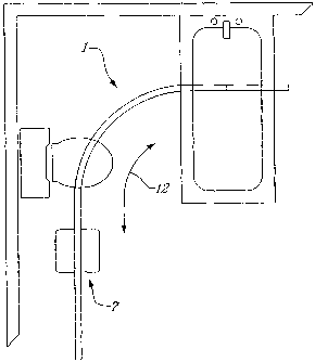
Figure 1, illustrates a known type of person handling system comprising a
single overhead
track component 1 which includes a single overhead curved carriage rail (or
track) fixed to a
ceiling by attachment means (not shown). This known system also features (see
figure 3d) a
wheeled carriage 5 attached or connected to a person lowering and raising
winch component
indicated generally as 7. The overhead track component 1 and the wheeled
carriage 5 are
19
CA 02465541 2004-04-30
WO 03/037239 PCT/CA02/01505
configured such that the wheels 9 of the carriage 5 engage the track 1 such
that the carriage 5 is
able to glide or roll along said track 1 A trolley or carriage drive motor 11
(e.g. electric
motor) is coupled to one of the carriage wheels 9 for inducing the wheels of
the trolley
carriage to cause the entire winch component 7 to be displaceable from one
position to
another i.e. (See figure 1) from the doorway of the bathroom shown to the
toilet seat or to the
bath tub and back in the direction of the arrow 12.
Referring back to figure 3d, the system includes a rechargeable battery 13 for
energizing the
trolley motor 11. Such a known system may further be associated with a battery
recharging
station (indicated generally by reference number 15) for recharging not only
the trolley battery
but also any other battery that may be associated with the system. The
recharge station
comprises a battery recharger 17 which is electrically coupled by wire 19 to a
suitable source
of electrical power which as shown is the electric outlet 21; the recharger
includes an electrical
contact strip 22 . The winch element 7 is on the other hand provided with
(known) electric
contact means 23 which is electrically coupled to the rechargeable battery 13
. In order to
recharge the battery the winch assembly is displaced until the electric
contact means 23 is
brought into slipping electrical contact with the electrical contact strip 2.
It is also known to associate with such a motorized person handling system, a
trolley motor
control mechanism (not shown). The trolley control mechanism is configured in
any suitable
manner so as to provide a first function whereby the trolley motor 11 may be
activated to
displace the trolley component along the rail a desired distance (and
direction). The trolley
control mechanism is also configured to provide a second (or recharge)
function whereby the
trolley motor may be activated so as to automatically displace the winch
element Ito the
recharging station 15 where the battery may be recharged; the trolley control
mechanism and
the recharge station 15 being provided with suitable corresponding electrical
connector means
to achieve this purpose such as shown generally in figure 3d.
Figure 2 illustrates what may be considered an X-Y rail system which can
provide for a greater
degree of movement of a winch assembly about a given work are or room i.e. as
compared to
the single rail system of figure 1. In addition to the winch travel rail 25
(i.e. the carriage
track) along which the winch element 7 is able to be displaced, this system
includes at least
two (parallel) spaced apart rails 27 and 29 which are attached to the ceiling
of a room or
which are supported at or near the ceiling by suitable support posts (in known
manner). The
area shown in dotted outline 31 is the area over which the winch element 7 may
be displaced.
The winch travel rail 25 is transversely attached to each of these parallel
rails 27 and 29 by
CA 02465541 2004-04-30
WO 03/037239 PCT/CA02/01505
respective wheeled trucks, carriages or by sliding members to allow manual
horizontal
displacement of the winch travel rail itself back and forth in the direction
of the arrow 33
shown (i.e. Y-direction); see for example figures 12 to 15 . The displacement
of this
transverse rail 25 itself in the direction of the arrow 33 provides a second
degree of freedom of
horizontal movement for the winch assembly shown. The first degree of
horizontal freedom
of movement of the winch assembly (X-direction) is of course along the
transverse rail itself
and is induced by the trolley motor (see arrow 35). These two horizontal
degrees of freedom
of movement are in addition to the vertical degree of movement which involves
the
displacement (i.e. Z-displacement) of a person who is attached in a harness in
the up and down
directions (see arrow 37 in figures 3a,3b and 3d).
As mentioned the transverse winch travel rail 25 is configured so that it may
be manually
pushed in the Y-direction. Alternatively, and in accordance with the present
invention, as shall
be discussed below (see figure 12 to 15), the transverse winch travel rail or
beam 25 may have
a motorized trolley(ies) or carriage(s) for the motorized displacement of the
transverse rail 25.
The person lowering and raising winch element 7 itself (in relation to the
systems shown in
figures 1 and 2 as well as for the present invention) may in particular
comprise a support
structure, a flexible elongated support member 39 connected to a harness
component 41 (see
figure 3d) for holding a person, a reel component connected to the support
structure for
winding up and paying out (i.e. unwinding) the flexible elongated support
member and a reel
electric motor,. The reel electric motor may be coupled to the reel component
in any suitable
(known) fashion such that when the reel motor is energised it may induce the
reel component
to unwind or wind up the flexible elongated support member, i.e. to vertically
raise or lower a
person as the case may be. For more details with respect to such a person
lowering and raising
winch assembly please see for example U.S. patent no. 6085368, the entire
contents of which
are incorporated herein by reference.
The disadvantage of the systems shown in figures 1 and 2 is that the
displacement of the winch
element 7itself along a rail 25 is motorized and thus subject to a preset
displacement speed. In
accordance with the present invention the winch element 7 and wheeled carriage
may
configured such that the winch element 7 may be displaced manually along the
carriage
support rail or under power from a trolley motor, as desired.
Turning to figures 3a, 3b and 3c these figures illustrate in schematic fashion
the variable
21
Printed: 02-02-2004 DESCPAMD CA0201505
functionality of a person handling system available in accordance with the
present invention. In
accordance with a person handling system of the present invention, the system
includes a
(carriage) displacement component comprising a motor element and a clutch
coupling element
able to couple and de-couple the motor to the trolley carriage. Figure 3 a
illustrates possible
movement of a supported person for a system in accordance with the present
invention wherein
the motor element is de-coupled from the trolley carriage such that horizontal
movement of the
winch supporting a person may be accomplished manually (i.e. by pulling or
pushing the person
in the support harness). Figure 3b illustrates possible movement of a
supported person for a
system in accordance with the present invention wherein the motor element is
coupled to the
trolley carriage such that horizontal movement of the winch supporting a
person may be
accomplished by appropriate energizing of the trolley motor (i.e. by
manipulation of the motor
control means 40). Figure 3c illustrates possible movement of the winch
assembly to a recharge
station either under motor power or else manually.
As mentioned above, in accordance with a person handling system of the present
invention, the system
includes a carriage displacement component comprising a motor element and a
clutch coupling element
able to couple and de-couple the motor to the trolley or carriage drive
wheels. Referring to figures 4 to
8, these figures illustrate a carriage component 43 and a winch assembly 45
which are associated, in
accordance with the present invention, with a reversible carriage motor 47 and
a coupling/de-coupling
clutch mechanism indicated generally at 49. The carriage component comprises
two pairs 51 and 53 of
opposed wheels 55. The wheels 55 (of each pair of wheels) are disposed on
opposite sides of a
downwardly extending central projection or web 57. The winch assembly is
attached to this central web
as by welding, mechanical mating (e.g. tongue/mortise type components, rivets,
etc.), or any other
suitable or desired mechanism.
Turning to figures 7 and 8 these schematically illustrate the engagement
between the support rail element
54 and the roller wheels 55 of the carriage element. Each wheel 55 of a pair
of wheels is supported on a
respective inwardly projecting lip 59 of the rail element 54. The lips 59
define a longitudinally
extending slot 61. The slot 61 is sized sufficiently so as receive
therethrough not only the central
projection or web 57 of the carriage but also the idler gear members 62 and
63. The periphery of each of
the idler gear 62 and 63 is provided with sprocket or gear teeth which are
sized and configured to mesh
with corresponding engagement openings (one of which is designated by the
reference numeral 67)
disposed around the related carriage wheels 55; if desired, or necessary, such
engagement may
alternatively be frictional in nature. The driving effort from the motor 47
(once coupled) is transferred
to the idler gears 62
22
CA 02465541 2004-04-30
10' 17-09-2003
CA 02465541 2004-04-30
WO 03/037239 PCT/CA02/01505
and 63 by the drive gear member 69 which is part of the rotatable driven
member of a
coupling/de-coupling component. Also shown in the figure 8 is an example means
of
attaching the support rail to the ceiling of a room. The attachment means is
shown in the form
of a bracket 70a which is for example held to the ceiling by a screw or the
like; the bracket is
provided with wing flanges attached to the rest of the bracket by a trunk
member. In use the
rail is slide onto the bracket such that the flange are in the channel of the
upper part of the rail
and the upper slot receives the stalk of the flange.
The trolley or carriage component 43 once installed onto the track or rail may
be displaced or
rolled about or along the track component either manually or under power from
the trolley
motor as described herein.
Referring to figures 9 and 10, these figures illustrate in exploded format an
example structure
for a coupling/de-coupling component of the present invention.
The driving member 71 and the driven member 73 are disposed coaxially relative
to the axis of
rotation of the drive shaft 75. Driving effort is transferable from the
trolley motor 47 via the
gearing member 77 to the drive shaft 75. The drive shaft 75 has a keyed end
75a for
engagement in a correspondingly shaped central opening 79 in the rotatable
driving member
71; the keyed end 75a and the opening 79 are shaped such that rotation of the
drive shaft 75
will induce a corresponding rotation of the rotatable driving member 71. The
rotatable driven
member 73 on the other hand is coaxially mounted relative to the drive shaft
75 but does not
engage the drive shaft 75 directly for its rotational movement. Rotational
movement of the
rotatable driven member 73 is induced by engagement between the driven member
73 and the
driving member 71.
Thus for the purposes of such engagement the driven member 73 is provided with
or is
configured to define a peripheral annular or ring member 80. The annular or
ring member 80
is provided with engagement means or elements in the form of internally
extending sprocket
or gear teeth (one of which is designated by the reference numeral 81)
configured for
engagement with engagement means or elements of the shuttle component
(indicated generally
as 83) as shall be discussed herein.
The rotatable driving member 71 on the other hand defines two slots 85
extending transversely
23
CA 02465541 2004-04-30
WO 03/037239 PCT/CA02/01505
(i.e. radially) to the axis of rotation of the drive shaft 75. The slots 85
are configured to
accommodate the shuttle component 83. The shuttle component slidingly engages
the wall
elements of the driving member 71 defining the slots 85 such that the shuttle
component is
able to be displaced to and fro in the slots 85 transversely to the axis of
rotation of the drive
shaft 75 ; the shuttle component 83 is in any event engaged or mounted in the
slots 85 such
that rotation of the driving member 71 induces a like rotation of the shuttle
component 83.
The shuttle component 83, as seen, comprises a pair of (opposed) separate
slide members 83a
and 83b; these two members 83a and 83b can be independently but simultaneously
displaced
radially outwardly or inwardly with respect to the drive shaft 75. For the
embodiment shown,
the shuttle component 83 (as well as the displacement element or member
mentioned below)
is configured such that displacement of the shuttle component for engagement
with the gear
teeth 81 of the annular or ring member 80 is able to provide a reversible type
of driving effort
(i.e. a driving effort alternatively in either the first or the second
rotational direction); the
direction of rotation being dictated by the direction of rotation of the drive
shaft.
Thus the opposed ends of the slide members 83a and 83b of the shuttle
component are
provided with any suitable (corresponding) engagement means configured for
mating
engagement or meshing with the engagement means or elements of the annular or
ring
member 80; namely, corresponding externally or outwardly extending sprocket or
gear teeth
87 for mating engagement or meshing with the internally or inwardly extending
sprocket or
gear teeth 81 of the ring member 80.
In accordance with the embodiment shown in figures 9 and 10, the means for
engaging and
disengaging the clutch mechanism comprises a displacement element or member 89
mounted
on the drive shaft 75; the displacement element or member 89 has a generally
ovoid type of
shape. The displacement member 89 includes a deformable collar element 89a
which in
conjunction with the spring clamp 91 frictionally clamps the displacement
member 89 to the
drive shaft 75. The frictional clamping is predetermined so as to provide
sufficient frictional
force to allow the drive shaft 75 to induce rotation of the displacement
member 89 sufficient to
force the separate slide members 83a and 83b apart until the gear teeth
thereof mesh with the
inner gear teeth of the annular or ring member 80 and thereafter the collar
element 89a slip
about the drive shaft 75 as it rotates.
The displacement element or member 89 is provided with a pair of curved cam
slots 92 and
24
CA 02465541 2004-04-30
WO 03/037239 PCT/CA02/01505
93 each curved slot being configured to slidingly engage a respective
projection 95 and 97
extending axially from a respective separate slide member of the shuttle
component 83 . The
displacement member 89 is also provided with opposed ends having curved (cam)
corners 99
for engagement with the inner curved surfaces 101 behind the respective gear
teeth. The
structure of the displacement member 89 is such so as to induce displacement
of the shuttle
component in the slots 85 in response to a rotational movement of said drive
shaft 75. Thus,
in response to a rotational movement of the drive shaft 75, the displacement
element or
member 89 is able to engage the shuttle component 83 so as to induce the
shuttle component
to alternately extend from and/or retract into said slot 85 into engagement or
disengagement
with the annular or ring member (e.g. by the intermeshing of gear teeth 81 and
87).
In other words as the ovoid shaped displacement member 89 is rotationally
displaced so that its
ends each mates with the inner curved surfaces 101 of the shuttle members this
action causes
the projections 95 and 97 of the shuttle slide members 83a and 83b to be
pushed along the
curved cam slots 92 and 93 inducing displacement of the corresponding slide
member until the
ovid member is in-line with the longitudinal axis passing through each of the
slide members;
this is the engagement configuration for the driven member and the driving
member. Once in
the extended configuration, the teeth of the shuttle member will engage the
interior teeth of the
driven member 73 and in turn induce rotation of the drive wheels 55 of the
trolley to cause the
trolley to move. Disengagement is induced by rotation of the drive shaft 75 in
the opposite
direction a sufficient degree such that the ovoid member is disposed
transversely to the said
longitudinal axis ; i.e. once the motor inducing motion is stopped, the ovoid
member is
returned to the neutral non-engagement position by rotation of the ovoid
member by the motor
in the opposite direction (a 1/4 turn) so as to cause the two slide members to
retreat into the
slots 85 and de-couple the driven member 73 and the driving member 71. In this
manner it is
to be understood that the rotation during the transfer of a driving effort may
be clockwise or
counterclockwise depending on the direction of rotation of the drive shaft.
It can be appreciated that when the ovoid is in the non engagement or neutral
position the
drive motor is not connected i.e. it is decoupled from the carriage wheels.
This configuration
will permit the manual displacement of the winch assembly along the support
track or rail i.e.
the motor itself will not offer any resistance to such displacement since it
is no longer
connected to the carriage wheels.
Referring to figures 1Oa,1Ob, IOc, 1Od and 10e, these figures illustrate in
general schematic
fashion the process of engaging and disengaging of the reversible motor 47 and
driven member
CA 02465541 2004-04-30
WO 03/037239 PCT/CA02/01505
73. As may be seen from figure 10a, the shuttle slide members 83a and 83b are
in a retracted
state which permits manual displacement of the carriage 43 since the motor 47
is no longer
able to act as a brake to such movement. Referring to figures 10b and 10c,
when motorised
movement of the carriage 43 is desired a pressure start button of a motor
control means is
depressed and held down until such time as the carriage has been moved the
desired distance;
the pressure button is of course to be configured such that the motor 47 will
only be energised
in the desired rotational direction as long as the button is depressed. As may
be seen from
figure l Oc rotation of the shaft 75 induces the slide members to extend
radially outward to
engage the inner teeth 81 which in turn passes the rotation movement on to the
driven member
73 and its gear 69. As may be seen from figures 7 and 8 rotation of gear 69
will induce the
rotation of the wheels 55 coupled to the idler gears 62 and 63 and thus cause
displacement of
the carriage 43. Once the desired distance has been traveled the user releases
the pressure start
button.. The motor control means is, however, provide with any suitable
sensing means for
generating a signal indicative of the release of the start button; this signal
is feed to a control
circuit which is configured to induce the motor to operate in an opposite
direction for a
predetermined opposite rotation of the drive shaft 75; i.e. the motor control
means induces the
motor to kick back in an opposite rotational direction so as to disengage the
slide members
and the inner teeth 81. Alternatively, the motor 47 may of course itself be
chosen on the basis
that on ceasing to be energised the motor will induce a slight opposite
kickback sufficient to
induce decoupling as discussed herein. The retraction of the slide members 83a
and 83b may
of course be accomplished by any other mechanically equivalent means e.g. by
bias spring
means; the slide members being biased in the retracted position and being
flung outwardly
against such bias on rotation of the shaft 75.
A rechargeable battery may be provided for energizing the trolley motor. Such
a known
system may further be associated with a battery recharging station. It is also
known to
associate with such motorized winch means a trolley motor control mechanism.
The trolley
control mechanism is configured in any suitable manner so as to provide a
first function
whereby the trolley motor may be activated to displace the trolley component
along the rail a
desired distance. The trolley control mechanism is also configured to provide
a second (or
recharge) function whereby the trolley motor may be activated so as to
automatically
displace the winch mechanism to a recharging station where the battery may be
recharged; the
mechanism and the recharge station being provided with suitable corresponding
electrical
connector means to achieve this purpose; the station being for example
connected to an
suitable source of electrical power.
26
CA 02465541 2004-04-30
WO 03/037239 PCT/CA02/01505
Although the winch assembly has been discussed in terms of using a battery as
a source of
electrical power, it is of course to be understood that the motor may be
connected to a source
of electrical power by any other (known) means.
Referring to figures 11 and 11 a these illustrate an alternate embodiment of a
clutch mechanism
wherein the shuttle component 100 is of unitary construction and the
displacement member
comprises a friction clamp 110 which can frictionally grip the sleeve 112 of
an anchor element
113 (which is disposed about a shaft drive shaft) with sufficient force to
rotate while pushing
against the projections 115 so as to induce engagement (or disengagement) and
then the
gripping part of the friction clamp 110 gripping the sleeve 112 is able to
slide or slip about the
shaft as it rotates. Otherwise the clutch mechanism of this embodiment is
constructed in more
less similar fashion and operates in much the same manner as that shown in
figure 9 and 10.
Figures 11 b, 11 c and 11 d show the displacement of the unitary shuttle
component 100.
The carriage system of the present invention as shown above may also be
advantageously
applied to an X-Y system. Thus in accordance with the present invention, the X-
Y system as
shown in schematic fashion in figures 12 to 15 has a transverse rail 125
connected to the
parallel secondary 126 and127 rails by two roller carriagesl28 and 129 ; the
carriage 129 is a
motorized carriage having a construction analogous to that of the carriage
displacement
component discussed with respect to figures 9 and 10 above (see also figures
4, 5 and 6). The
motorised carriage 129 has the same type of motor element 47 and clutch
coupling element 49
as shown in figures 9 and 10 but does not of course have a winch assembly
associated
therewith; the motorised carriage 129 may be provided with a rechargeable
battery (not
shown) for exergizing the motor 47. The motorised carriage has the same type
of carriage
component 43 as also shown in figures 4, 5 and 6 but carriage component 43 is
further
provided with horizontal stabilization rollers 130 for engaging the side wall
of the channel of
the secondary rail 127. The carriage component 43 is further attached (e.g. by
rivets, nut/bolt
combinations, etc.) to a lower carriage component 143 (wheels/roller not
shown) of the same
construction (but unmotorised) for connecting the carriage component 43 to the
transverse rail
125; when viewed for the top the two carriage elements together have a cross-
like aspect.
The roller carriage 128 (see figure 15a) has the same type of construction as
the carriage 129
except that it is not associated with a motor and clutch as is in the case of
carriage 129. An
alternate carriage construction 128a is shown in figure 15b; as may be seen
the lower carriage
component is not provided with wheels but instead has slider members 145 for
sliding
engagement with the inner walls of a rail channel.
27
CA 02465541 2004-04-30
WO 03/037239 PCT/CA02/01505
The shown X-Y system can have both the advantages of a fully motorized system
and those of
a manual system i.e. when the respective clutches are not engaged, the motor
for the winch
assembly and/or the motor for the transverse rail, the winch assembly and / or
the transverse
rail may be displaced manually in accordance with the desires or needs of the
operator.
As mentioned above the clutch mechanism may take on any other desired or
necessary form.
Figures 16, 16a,17a, 17b, 17c and 18 illustrate in schematic fashion other
forms of clutch
mechanisms. Turning to figures 16 and 16a, these figures show a clutch
mechanism using a
magnetic coupler 150 to couple the motor 47 to the gear 69. Figures 17a, 17b
and 17c show a
clutch mechanism using a using a secondary motor 153 to displace a mechanical
coupler
element 155 to couple the motor 47 to the gear 69. The coupler in figure 18 on
the other hand
exploits a rocker arm 160 attached to a pivot 162. The motor 47 is attached at
one end of the
arm and a friction roller 163 is attached to the other end of the arm 160. The
motor 47 is
coupled to the friction roller 163 by a pulley means not shown. The mechanism
is also
provided with displacement means not shown for pivoting the rocker arm 160 up
and down in
the direction of the arrow 164 so as to engage or disengage the friction
roller 163 with the
underside of rail 168.
Referring to figures 19a, 19b, 19c and 19d, the X-Y system described above may
also, for
example, be provided with a suitably configured (mechanically and/or
electronic) control
means 170 for provoking the returning or displacing of the winch assembly 45
to a recharge
station 15 automatically. The recharging station 15 may for example (as shown
at an end of
secondary rail 127) be disposed at one end of one of the two parallel
secondary rails. The
control means 170 may for example comprise recharge switch means (not shown).
The recharge switch means may be configured in any suitable fashion to
cooperate with the
carriage motor and rechargeable battery of the winch assembly 45 such that
once the recharge
switch means is triggered (i.e. placed in the "on" configuration), the
carriage battery energizes
the winch assembly carriage motor so as to induce the winch assembly 45 to
travel along the
transverse rail (in the direction of the arrow 172 ), i.e. toward the end
thereof provided with
the motorised carriage 129 of the transverse rail 125
The winch assembly 45 may be provided with a further primary switch means
(indicated
generally at 176) configured to electrically disconnect the winch assembly
motor battery from
the winch assembly carriage motor once the winch assembly has arrived at a
predetermined
28
CA 02465541 2004-04-30
WO 03/037239 PCT/CA02/01505
position adjacent the end of the transverse rail, i.e. the primary switch
means 176 may
comprise a physical projection (i.e. pole) displaceable from an "on" position
to an "off'
position by contact with the secondary rain or projection thereof. Once the
pole is in the "off'
position the winch assembly carriage motor is no longer energised by the
battery and
movement along the transverse rail is stopped.
The motorised carriage 129 of the transverse rail on the other hand may also
be provided with
secondary switch means indicated generally at 178). The secondary switch means
178 may
be configured in any suitable or desired fashion to electrically connect the
battery of the
transverse rail carriage motor with the transverse rail carriage motor once
the winch assembly
has arrived at a predetermined position adjacent the end of the transverse
rail, i.e. the
secondary switch means 178 may thus also comprise a physical projection (i.e.
pole)
displaceable from an "off' position to an "on" position by contact with the
housing of the
winch assembly. Once the pole is in the "on" position the transverse rail
carriage motor is
energised and induces the transverse rail to travel in the direction of the
arrow 180 towards the
recharge station 15.
The motorised carriage of the transverse rail may also be provided with an
additional tertiary
switch means (indicated generally at 182). The tertiary switch means 182 may
be configured
in any suitable or desired fashion to electrically disconnect the battery of
the transverse rail
carriage motor from the transverse rail carriage motor once the winch assembly
has arrived at
the recharge station, i.e. the tertiary switch means may thus also comprise a
physical
projection (i.e. pole) displaceable from an "on" position to an "off' position
by contact with
the housing of the recharge statio or projection thereof. Once the pole is in
the "off' position
the transverse rail carriage motor is no longer energised and movement of the
transverse rail is
halted once the winch assembly rechargeable battery is brought into electrical
connection
with the battery recharge station (see above figure 3d for such electrical
connection ).
As may be appreciated from the above, under the sequential influence of the
drive motors
mentioned above the winch assembly may be made to travel along the transverse
rail and then
the transverse rail may be made to carry the winch assembly to the recharge
station in
automatic fashion.
Thus in accordance with the invention when the operator desires to send the
system to the
recharging configuration, the operator merely presses the appropriate button
(i.e. switch
29
CA 02465541 2004-04-30
WO 03/037239 PCT/CA02/01505
control) on the control means 170. In this case the control means will
initiate motorization of
the winch assembly followed by motorization of the transverse bar so that
motion of the winch
assembly coupled with motion of the transverse bar will transport the winch
assembly to the
charging station. It is of course to be understood that at the recharge
station 15, the battery
for the tranverse rail carriage motor may also, if so desired or necessary be
recharged as
described herein (see figure 3d for an example of such electrical connection
which may be
adjusted as necessary or desired to permit such recharging).
Alternatively with both carriage motors in the de-coupled configuration the
winch assembly
may be manually displaced to the recharge station, i.e. along the transverse
rail and then the
transverse rail to the recharge station.