Note: Descriptions are shown in the official language in which they were submitted.
CA 02466006 2004-03-23
WO 03/029132 PCT/US02/30420
RELOCATABLE STORAGE TANKS FOR LIQUIDS AND GRANULAR
MATERIALS
CROSS-REFERENCE TO RELATED APPLICATION
[0001] This application claims the benefit of United States Provisional Patent
Application
Number 60/325,461 filed September 28, 2001 and United States Utility Patent
Application
Number 10/245,631 filed September 17, 2002.
1o BACKGROUND OF THE INVENTION
Field of the Invention
[0002] The present invention generally relates to flexible storage tanks, and
more
particularly to a flexible relocatable storage tank for flowable materials
such as liquids and
15 granular material.
Description of the Related Art
[0003] Conventional structures for relocatable and collapsible tanks utilize
designs such
as a pillow or bladder tank, available from Aero Tec Laboratories, Inc., NJ,
USA and others,
2o which consists of a bag made in the shape of a pillowcase using flexible
material. When empty,
the bag folds flat and may be rolled or folded for storage and shipment. The
filling/discharge
flange is integrated into the top panel of the material, and the storage
volume is sealed at all
times with a negligible air or vapor pocket. This conventional design is a
formless package
when folded for transport with no real strong confluence points to allow for
lifting to load onto a
2s transport. In larger sizes, it must be loaded onto a single stiff pallet to
allow for lifting by a
forklift or crane. One of the other drawbacks of this conventional design is
that the pillow tank
does not tolerate high site slopes, and requires relatively large site areas
because the average
depth of the stored liquid inside of the tank is low. Moreover, such tanks
appear to be relatively
expensive, and do not lend themselves to the storage of granular materials.
Also, liquids stored
3o in the pillow tanks, which are exposed to bright sunlight, get extremely
hot. This is undesirable
for fuels or potable water. In order to ameliorate this effect, a cover needs
to protect the tank
from the sun, which requires a considerable structure to span the overall
exposed surface of the
tank.
CA 02466006 2004-03-23
WO 03/029132 PCT/US02/30420
[0004] Another conventional design uses rigid tanks, which are built with
rigid panels
forming the sides, and often a rigid metal support frame. The loads imposed by
the stored liquid
or grain are carried directly by these panels. These tanlcs may have a plastic
membrane liner;
however, this is not structural, rather it is provided more for sealing
purposes only. Such tanks
usually require prepared unsloped sites.
[0005] Other conventional designs consist of flexible bags with an external
frame, such
as the type disclosed in United States Patent Number D334,238 and issued to
Spedini, further
illustrated in Figure 1 herein. These designs are used especially for above-
ground swimming
pools, and consist of a tank using a bag of strong flexible material supported
by an external metal
io frame consisting of a rim in the horizontal plane, supported off the ground
by a series of inclined
metal posts. As shown in Figure l, the flexible bag is a structural member
which carries the
loads imposed by the weight of the peripheral liquid or grain to the rim of
the tank, and hence to
the ground via the supporting posts. The weight of the liquid/grain in the
central area of the tank,
where the fabric is in contact with the ground, is supported directly by the
ground. This
15 conventional design offers a highly portable, low weight tank, which can be
quickly and easily
installed and dismantled. However it suffers from the following disadvantages.
[0006] First, the external structure of the conventional fabric tank must be
considerably
over-designed for the chosen depth of the associated liquid/grain because for
depths differing
from the design depth, the rim and external posts of the tank are subjected to
extra bending loads,
2o as depicted in the illustration of the conventional design used in practice
shown in Figure 2. This
is particularly critical for the posts, which are subjected to significant
compression forces,
because the applied bending significantly increases the tendency for the posts
to buckle. A
second disadvantage of the conventional design shown in Figures l and 2 is
that for similar
reasons related to the varying depths of the associated liquid/grain, the
problem is exacerbated if
25 the tank is to be used in an emergency or unprepared, sloping, or
undulating ground. Typically,
these conventional tanks are severely limited to a few degrees of slope. Thus,
such designs with
external frames are used primarily for aboveground swimming pools, where the
water is
typically at or close to design depth, and such designs have found no
functional application in
storage tanks, which of course, must accommodate a large range of depths.
3o [0007] Moreover, the conventional fabric tank designs use relatively light
fabrics for the
bag and several light rigid components for the external frame. However, it is
really only suitable
for applications which can accept an open liquid surface, thereby limiting its
use to non-potable
water. Moreover, these conventional designs do not easily accept other
granular materials, nor
2
CA 02466006 2004-03-23
WO 03/029132 PCT/US02/30420
do they tolerate more than minimal slopes, and the frame must be stiffened
appreciably to cope
with partially filled conditions.
[0008] Therefore, there is a need for a relocatable, storage tank for flowable
materials
such as liquids and granular materials comprising a bag of flexible material
and having a
generally square, rectangular, or circular shape, resting on a solid surface,
together with at least
one central post which supports the upper portion of the bag, wherein the post
aids in carrying
the weight of the flowable materials to the ground, thereby reducing the
associated mechanical
tensions in the fabric of the flexible material. Moreover, there is a need for
a larger flexible
relocatable storage tank for flowable materials such as liquids and granular
materials which can
1o improve the ease of relocation of the stored materials, and which allows
for the use of the storage
tanlc in confined and sloping sites, especially for temporary and/or emergency
situations.
SUMMARY OF THE INVENTION
15 [0009] In view of the foregoing and other problems, disadvantages, and
drawbacks of the
conventional storage tanks the present invention has been devised, and it is
an object of the
present invention to provide a structure for a relocatable storage tank for
liquids and granular
materials. It is another object of the present invention to provide a
structure for a relocatable
storage tank for liquids and granular materials which improves the ease of
relocation of the tank,
2o and to allow use of the tank in confined and on sloping sites, especially
for temporary and
emergency conditions. It is a further object of the present invention to allow
for larger depths of
storage for the stored liquids in the storage tank. Still another object of
the present invention is
to allow for filling, storage, and discharge of granular materials from the
storage tang. Yet
another object of the present invention is to collect and carry the peripheral
liquid/granular loads
25 in tension, and take these loads to the ground in compression in at least
one internal support
system.
[0010] In order to attain the objects suggested above, there is provided,
according to one
aspect of the invention, a storage tank for flowable material such as liquids
and granular
material, wherein the storage tank comprises a container of flexible material,
wherein the flexible
3o material comprises a base portion for engaging a supporting surface, and at
least one supporting
post system mounted over the base portion and supported by the suppot-ting
surface, wherein the
flexible material extending upwardly from the base portion forms a side
portion and an upper
portion of the storage tank, and is secured to the supporting post system.
Furthermore, the
storage tank of the present invention is provided in mufti-geometrical
embodiments including
CA 02466006 2004-03-23
WO 03/029132 PCT/US02/30420
generally square, rectangle, circular, and polygonal shapes. In an alternative
embodiment, the
storage tank comprises an upper cap positioned on the upper portion of the
storage tank. In
another alternative embodiment, the storage tank further comprises support
cables attaching the
supporting post system to the. supporting surface.
[0011] Additionally, the supporting post is generally rigid. Also, in an
alternative
embodiment, the supporting post is generally solid. Alternatively, the
supporting post is
generally hollow. Also, the supporting post may be embodied as a float. In
another
embodiment, the at least one supporting post system comprises a plurality of
supporting posts
interconnected by a linking element. Still alternatively, the storage tank
comprises an outer
l0 support fabric over the flexible material. Additionally, the storage tank
may further comprise a
covering sheet over the storage tank, embodied as a fly sheet for solar
protection and slope
stabilization. The fly sheet could also provide a cover from rain, snow,
leaves, etc.
[0012] In an alternative embodiment, a storage tank for flowable material such
as liquids
and granular material comprises a container of flexible material, wherein the
flexible material
15 comprises a base portion for engaging a supporting surface, and at least
one support system
positioned over the base pot-tion, wherein the flexible material extends
upwardly from the base
portion to form a side portion of the storage tank, and is secured to one of a
support rim and the
support system, wherein the support rim is positioned over the base portion.
The support system
comprises one of a post and a float. Moreover, the post may be either solid or
hollow. In an
20 alternative embodiment, the storage tank further comprises a plurality of
cables attaching the
support rim to the support system. Furthermore, in another embodiment, the at
least one support
system comprises a plurality of supports interconnected by a linking element.
Alternatively, the
storage tank comprises an outer support fabric over the flexible material.
Additionally, the
storage tank may further comprise a covering sheet over the storage tank,
embodied as a fly sheet
25 for solar protection and slope stabilization.
[0013] In another alternative embodiment, the present invention provides a
storage tank
for flowable material such as liquids and granular material, wherein the
storage tank comprises a
flexible bag having a side portion and an upper portion. The storage tanlc
further comprises at
least one support structure contained within the flexible bag, whereby the
support structure is
30 positioned below the upper portion of the flexible bag, wherein the
flexible bag is secured to a
supposing surface, and wherein the support structure is secured to the
supporting surface.
Additionally, the flexible bag extends upwardly from the supporting surface,
and is secured to
one of a support rim and the support structure, wlierein the support rim is
positioned below the
upper portion of the flexible bag. Alternatively, the storage tank further
comprises a plurality of
4
CA 02466006 2004-03-23
WO 03/029132 PCT/US02/30420
cables attaching the support rim to the support structure. The support
structure may be embodied
as a post, which may be hollow or solid, or the support structure may be
embodied as a float.
Still alternatively, the at least one support structure comprises a plurality
of supports
interconnected by a linlcing element. In another embodiment, the storage tank
further comprises
an outer support fabric over the flexible material. Additionally, the storage
tanlc may further
comprise a covering sheet over the storage tank, embodied as a fly sheet for
solar protection and
slope stabilization.
[0014] The present invention overcomes the several disadvantages of the
conventional
designs. For example, the present invention provides for an essentially
vertical storage of the
to tank when it is not in use (i.e., stored footprint is very small), without
requiring accessory
equipment. Also, the present invention is easily loadable and carried to site
by a forklift, crane,
etc., without requiring accessory lifting gear such as pallets or a carrying
case. The present
invention tolerates installation and filling on sloping sites. Moreover, on
steep slopes
(approximately 10 degree grade), the present invention can easily be made
stable by utilizing
15 simple guy ropeslcables attached to the central post and anchored to the
high side of the site.
Additionally, the present invention's central post provides a support for a
fly sheet for solar
heating and UV protection at a low cost. In fact, it is feasible to use this
fly sheet to create some
shrapnel protection for military use.
[0015] Other advantages of the present invention are that the present design
allows for
20 laxger depths of stored liquids than conventional flexible tanks, and hence
smaller footprint areas
for a given capacity, which is ideal at congested or restricted sites.
Furthermore, the present
design accommodates for filling, storage, and discharge of granular materials
at lower production
costs compared to traditional designs.
25 BRIEF DESCRIPTION OF THE DRAWINGS
[0016] The foregoing and other objects, aspects and advantages will be better
understood
from the following detailed description of the preferred embodiments of the
invention with
reference to the drawings, in which:
30 [0017] Figure 1 is a schematic diagram of a conventional fabric tank
design;
[0018] Figure 2 is a schematic diagram of a conventional fabric tank design;
[0019] Figure 3A is a schematic diagram of a storage tank according to the
present
invention;
CA 02466006 2004-03-23
WO 03/029132 PCT/US02/30420
[0020] Figure 3B is a schematic diagram of the storage tank of Figure 3A on a
sloped
surface according to the present invention;
[0021] Figure 3C is a schematic diagram of the storage tank of Figure 3A on a
sloped
surface according to the present invention;
[0022] Figure 4A is a schematic diagram of an alternative embodiment of a
storage tank
according to the present invention;
[0023] Figure 4B is a schematic diagram of an alternative embodiment of the
storage tank
of Figure. 4A according to the present invention;
[0024] Figure 4C is a schematic diagram of an alternative embodiment of the
storage tank
of Figure 4A according to the present invention;
[0025] Figure 4D is a schematic diagram of an alternative embodiment of the
storage
tank of Figure 4A according to the present invention;
[0026] Figure SA is a top view of a storage tank configuration according to
the present
invention;
[0027] Figure 5B is a top view of an alternative storage tank configuration
according to
the present invention;
[0028] Figure SC is a top view of an alternative storage tank configuration
according to
the present invention;
[0029] Figure SD is a top view of an alternative storage tank configuration
according to
the present invention;
[0030] Figure 5E is a top view of an alternative storage tank configuration
according to
the present invention;
[0031] Figure 5F is a top view of an alternative storage tank configuration
according to
the present invention;
[0032] Figure SG is a top view of an alternative storage tank configuration
according to
the present invention;
[0033] Figure SH is a top view of an alternative storage ta~~lc configuration
according to
the present invention;
[0034] Figure SI is a top view of an alternative storage tank configuration
according to
3o the present invention;
[0035] Figure SJ is a top view of an alternative storage tank configuration
according to
the present invention;
[0036] Figure SIB is a top view of an alternative storage tank configuration
according to
the present invention;
6
CA 02466006 2004-03-23
WO 03/029132 PCT/US02/30420
[0037] Figure 6 is a schematic diagram of an alternative embodiment of a
storage tank
according to the present invention;
[0038] Figure 7 is a schematic diagram of an alternative embodiment of a
storage tank
according to the present invention;
[0039] Figure 8 is a schematic diagram of an alternative embodiment of a
storage tank
according to the present invention;
[0040] Figure 9A is a schematic diagram of an alternative embodiment of a
storage tank
according to the present invention; and
[0041] Figure 9B is a schematic diagram of an alternative embodiment of a
storage tank
according to the present invention.
[0042] Figure 9C is a schematic diagram of an altenzative embodiment of a
storage tank
according to the present invention.
[0043] Figure 1 OA is a schematic diagram of an alternative embodiment of a
storage tank
according to the present invention;
[0044] Figure l OB is a schematic diagram of an alternative embodiment of a
storage tank
according to the present invention; and
[0045] Figure lOC is a schematic diagram of an alternative embodiment of a
storage tank
according to the present invention.
DETAILED DESCRIPTION OF PREFERRED
EMBODIMENTS OF THE INVENTION
[0046] As previously mentioned, there is a need for a novel relocatable
storage tank for
liquids and granular materials. The present invention provides a relocatable
storage tank, which
may be easily stored, transported, and assembled if necessary, on unprepared
and/or sloping
sites. The present invention provides a flexible storage tank capable of
taking some of the
weight of the stored liquid or grain down to the ground through a support
system, embodied as
vertical post(s), thereby relieving the flexible bag of some of the weight,
which in turn, allows
for reduced mechanical tensions iii the bag.
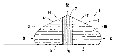
[0047] Referring now to the drawings, and more particularly to Figures 3
through 10,
there are shown preferred embodiments of the structures according to the
present invention.
Specifically, Figure 3A illustrates a storage tank 1 positioned on a level
planar supporting
surface 2. The storage tank 1 comprises a container 3 of flexible material 4
for storing internal
contents such as liquids and granular materials 19 at varying design depths 9.
The container 3
7
CA 02466006 2004-03-23
WO 03/029132 PCT/US02/30420
further comprises a base portion 5 for engaging the supporting surface 2.
Moreover, the
container 3 further comprises at least one supporting system (support
structure) 6 preferably
embodied as a post 6 mounted over the base portion 5 and is supported by the
supporting surface
2. The flexible material 4 extends upwardly from the base portion 5 to form
the sides 8 and the
upper portion 17 of the tank l, and is secured to the supporting post 6 at the
upper portion 17 of
the container 3.
[0048] The internal frame support system 11 of the tank 1 comprises the at
least one
colurml or post 6, placed inside the suitably shaped flexible bag 4. In this
design, all of the
peripheral liquid/granular loads are carried up the fabric sides 8 to the top
7 of the central post 6.
l0 Figure 3A shows the storage tank 1 on a zero degree grade flat site 2,
whereby all of the
horizontal components of the loads are balanced, and the only load to be
carried by the post 6 is a
vertical compression load, which the generally large-diameter single post 6
can easily withstand
without buckling.
[0049] The angle of the top or "roof' 17 (the angle of the roof is that
portion above the
15 waterline 9 to the top 7 of the post 6) of the tank 1 may be selected,
preferably at any angle less
than approximately 80 degrees, but for acceptable post heights, it is best
selected no greater than
approximately 45 degrees from the horizontal. The shape of the curved side 8
of the fabric bag 4
is best calculated for the chosen roof angle at the design depth 9, when the
fabric tensions are
highest. For two dimensional balance, the curve 8 is established by making the
local radius of
2o curvature of the bag 3 at each liquid (or granular material) depth 9
according to the formula
R=K(T/H), where R is the local radius of curvature, T is the fabric tension, H
is the local depth
of the stored material, and I~ is a constant and depends on the density of the
stored material.
From the design level 9 to the top 7 of the posts) 6, the bag 3 is generally
straight.
[0050] The bag 3 may distort somewhat from this datum shape on sloping sites,
and when
25 the tank is less than full, but this is accommodated by the flexible fabric
4, and the tensions do
not increase significantly beyond the design datum.
[0051] If the site 2 is sloping or undulating, as indicated by the five degree
slope in
Figure 3B, the horizontal loads will not be completely in balance, resulting
in an overturning and
bending moment M in the central post 6. For effective site slopes up to
approximately 10
3o degrees, as indicated in Figure 3C, this overturning and bending moment M
can easily be carried
by the generally short, large diameter column 6 without overturning or
buckling. Furthermore,
for such steep site slopes, a smaller diameter central column 6 may be used
and be relieved of
some or all of this overturning and bending moment M by attaching support
cables 10, such as
8
CA 02466006 2004-03-23
WO 03/029132 PCT/US02/30420
guy wires/cables 10 to the support post system 6, and preferably at the top 7
of the column 6, and
anchoring the wires 10 to the ground 2 on the upper sides(s) 161 of the site
2.
[0052] This present design with an internal frame 11 makes it feasible to use
existing
fabrics 4 for water depths 9 up to approximately 10 feet, and grain depths 9
up to approximately
20 feet, with adequate factors of safety on fabric strength, for a large
variety of square,
rectangular, polygonal, and circular tank shapes.
[0053] The entry/exit locations 12 for the stored material 9 may be within the
posts) 6
themselves, or in the fabric bag 4. The concept allows for virtually any
shape/configuration of
the tank 1. For example, Figure 4A shows the geometry for a "square" tank 1
with a liquid depth
l0 9 one-third of the overall length L of the tank l, and a sloped top or roof
17 to shed rain and
snow. The length L is the overall length of the tank 1 when filled. This is
within a few % of the
length of the tank 1 when empty. The length L of this configuration may be
increased without
increasing the liquid depth 9, as shown in Figure 4B. If eventually the
central post 6 becomes
unacceptably high, then multiple posts 6 can be used, and interconnected
together with a linking
15 element 13, as shown in Figure 4C. Alternatively, the slope of the roof 17
may be
increased/decreased as shown in Figure 4D, depending on the rate of rain and
snow to be shed,
or the granular material to be stored. Preferably, for granular material
storage, the design is best
arranged with a roof angle steeper than its angle of repose.
[0054] In an identical fashion, the width of the tank may also be increased,
giving rise to
20 multiple configurations shown in Figures SA through SIB. It should be
appreciated by those
skilled in the art, that other configurations not specifically illustrated
herein, may be used within
the context of this invention.
[0055] For non-emergency situations, where it is feasible and economical to
create a
depression 14 in the ground 2 below the tank 100, the fabric bag 4 can be
shaped whereby the
25 base portion 5 of the storage tank 100 fits into this depression 14, as is
depicted in Figure 6. This
allows practically all of the stored liquid to be drawn off, and all of the
stored granular material
19 to be easily discharged (by auger or by suction) as long as the depression
angle is greater than
the angle of repose. Alternatively, an inverted conical or pyramidal
depression may be formed
by an elevated rigid platform 52, to allow for unloading of the container by
gravity as seen in
3o Figure lOB.
[0056] Next, as illustrated in Figure 7, if necessary, to reduce the non-
divisible weight for
installation or transportation, or to carry higher tensions from increases in
stored depth 9, the
fabric bag 4 can comprise a load-carrying outer support fabric 44 and an
inside non-load-
carrying plastic liner 15 for sealing the liquids or grains 19. The outer
support fabric 44, which
9
CA 02466006 2004-03-23
WO 03/029132 PCT/US02/30420
is positioned over the flexible material 4, may comprise, for example, a
polymer coating on a
woven base or scrim cloth. The inner plastic liner 15 may comprise, for
example, a single film
of polymer, which could expand with the water depth 9. This solution may be
particularly useful
for military purposes, where the tank 1 could be shipped with several
different plastic liners 15,
to be chosen or rotated at the site to allow for storage of fuel, potable
water, etc. It could also be
useful to form a completely sealed storage volume 117, which needs no venting.
[0057] In all or most of the configurations described above, the required
vertical loads
could alternatively be provided by pressurized buoyancy bags) 16 floating on
the liquid/grains
19 acting as the support system, as shown in Figure 8, instead of by rigid
post(s). Figure 9A
to shows the geometry for a storage tank 1 with a fixed bottom cap 20 and a
removable top cap 37.
The upper cap 37 is positioned on the upper portion 17 of the storage tank 1.
The fabric 4 may
be constructed using, for example, a 22 oz/sq.yd. high strength PVC/polyester
fabric. It may be
folded and placed inside the hollow supporting post system (cylinder) 6 for
transportation and
storage. The diameter of cylinder 6 is sufficient to stabilize the tank 1 when
fully or partially
15 filled 9, even on site slopes of 8 to 10 degrees. The fabric bag 4 of the
container 3 can either be
carried all the way to the central post 6, as indicated in Figure 9A, or may
be terminated just
above the waterline 9 in a metal rim 21, as shown in Figure 9B, while straps
or cables 22 carry
the fabric loads to the central post 6.
[0058] The present invention may be practiced in several alternative
embodiments
2o depending on the application of use. For example, the traditional use is to
utilize a square
planform tank 1 with a single vertical post 6, as illustrated in Figure 4A. In
emergency fire
fighting or fish farming use, the open tank 101 design of the present
invention is most suitable,
which requires taking the fabric loads to a stiff metal support rim 21, and
carrying those loads to
the support system (post) 6 by cables or straps 22 as shown in Figure 9B. For
potable water
25 uses, the top 17 of the storage tank 1 should be sealed, which is best
performed by continuing the
fabric 4 directly to the support system (post) 6, either in a stronger fabric
4 at the top 7 or by
reinforcing straps (not shown) welded to the fabric.
[0059] The preferred post configuration for non-potable water is to make the
post 6 as a
hollow canister (cylinder) large enough to contain the fabric bag 4 when it is
folded. This means
30 that the bag 4 can itself be stored in the rigid canister 6 when the tank 1
is not in use, protected
from UV and dust, and storage and handling damage. The footprint of the
canister 6 is generally
small which is important for storage and shipment in readiness for emergency
applications. For
potable water tanks 201, as shown in Figure 9C, the post 60 is made with a
generally small
diameter (with a generally wider base 131 and top 132), and the fabric bag 40
is folded up on the
CA 02466006 2004-03-23
WO 03/029132 PCT/US02/30420
outside of the narrow post 60. An upper cap 30 may also be provided. This
configuration does
not provide the bag storage protection, which the canister design provides.
However, it avoids
any possible contamination, which might otherwise be caused by inserting the
canister 6 into the
bag 4 on site.
[0060] Some of the alternative embodiments of the present invention include
using multi-
shaped tanks with multiple posts, such as those described in Figures SA
through SK. Other
embodiments include having the bags 4 shaped to fit a level, conical, or V-
shaped site 2, or to be
mounted on the surface of a raised platform 52 with a rigid surface providing
the bottom to the
tank 301, 401, 501 as shown in Figures l0A through l OC, respectively.
Alternatively, a
to substitute buoyant sphere 16 for generally square-shaped tanks l, as seen
in Figure 8, or a
buoyant tube 25 positioned along the centerline of a generally rectangular
tank 1, may be used
instead of the posts) 6, as shown in Figure SJ. Still alternatively, for
generally larger tanks, use
of a structural outer bag 14, which may be a woven mesh or net to carry the
loads and a thinner
non-porous liner 15 to seal the liquid may be incorporated. Moreover, the
loads generally
15 increase near the support posts 6. In order to carry increased tensions,
several alternatives exist.
First, heavier fabrics 4 may be used near the upper portion 17 of the storage
tank 1. Second,
welded on webbing straps 10, 22 may be used. Third, rim tubes 125 may be used
to collect the
loads and distribute them to the top 7 of the posts 6 by cables or straps 122
(see Figure SK).
Fourth, catenary cables (not shown) may be used.
20 [0061] In the alternative embodiments described above, and as illustrated
in Figures l0A
through 10.C, the fabric bag 4 and support structure 6 are attached directly
to the supporting
surface (ground 2 as seen in Figures l0A and l OC, or a raised platform 52,
such as the bed of a
transportation vehicle as seen in Figure l OB) thereby avoiding the necessity
of having a fabric
base portion 5 as required by the embodiments illustrated in Figure 3A and
Figure 6. In
25 FigurelOA, the storage tank 1 comprises a flexible bag 4 having a side
portion 8 and an upper
portion 17; and at least oue support structure 6 contained within the flexible
bag 4, wherein the
support structure 6 is positioned below the upper portion 17 of the flexible
bag 4, wherein the
flexible bag 4 is secured to a supporting surface 2, and wherein the support
structure 6 is secured
to supporting surface 2.
30 [0062] The present invention overcomes the several disadvantages of the
conventional
designs. For example, the present invention provides for an essentially
vertical storage of the
tank when it is not in use, without requiring accessory equipment (i.e.,
stored footprint is very
small). Also, the present invention is easily loadable and carried to site by
a forklift, crane, etc.,
without requiring accessory lifting gear such as pallets or a carrying case.
The present invention
11
CA 02466006 2004-03-23
WO 03/029132 PCT/US02/30420
tolerates installation and filling on sloping sites. Moreover, on steep slopes
(approximately 10
degree grade), the present invention can easily be made stable by utilizing
simple guy
ropes/cables 10 attached to the central post 6 and anchored to the high side
161 of the site 2.
Additionally, the present invention's central post 6 provides a support for an
optional coversheet
333 over the storage tank, embodied as a fly sheet 333 for solar heating and
LTV protection as
well as slope stabilization at a low cost, as seen in Figure 9B. In fact, it
is feasible to use this fly
sheet 333 to create some shrapnel protection for military use. The fly sheet
333 could also
provide a cover from rain, snow, leaves, etc.
[0063] Other advantages of the present invention are that the present design
allows for
to larger depths of stored liquids than conventional flexible tanks, and hence
smaller footprint areas
for a given capacity, wluch is ideal at congested or restricted sites.
Furthermore, the present
designs accommodate for filling, storage, and discharge of granular materials
at lower production
costs compared to traditional designs.
[0064] While the invention has been described in terms of preferred
embodiments, those
skilled in the art will recognize that the invention can be practiced with
modification within the
spirit and scope of the appended claims.
12