Some of the information on this Web page has been provided by external sources. The Government of Canada is not responsible for the accuracy, reliability or currency of the information supplied by external sources. Users wishing to rely upon this information should consult directly with the source of the information. Content provided by external sources is not subject to official languages, privacy and accessibility requirements.
Any discrepancies in the text and image of the Claims and Abstract are due to differing posting times. Text of the Claims and Abstract are posted:
| (12) Patent Application: | (11) CA 2466042 |
|---|---|
| (54) English Title: | METHOD AND SYSTEM FOR CODE REUSE AND CAPACITY ENHANCEMENT USING NULL STEERING |
| (54) French Title: | PROCEDE ET SYSTEME PERMETTANT DE REUTILISER UN CODE ET AMELIORATION DE CAPACITE FAISANT APPEL A UN DISPOSITIF NON ORIENTABLE |
| Status: | Deemed Abandoned and Beyond the Period of Reinstatement - Pending Response to Notice of Disregarded Communication |
| (51) International Patent Classification (IPC): |
|
|---|---|
| (72) Inventors : |
|
| (73) Owners : |
|
| (71) Applicants : |
|
| (74) Agent: | SMART & BIGGAR LP |
| (74) Associate agent: | |
| (45) Issued: | |
| (86) PCT Filing Date: | 2002-11-01 |
| (87) Open to Public Inspection: | 2003-05-15 |
| Examination requested: | 2004-04-30 |
| Availability of licence: | N/A |
| Dedicated to the Public: | N/A |
| (25) Language of filing: | English |
| Patent Cooperation Treaty (PCT): | Yes |
|---|---|
| (86) PCT Filing Number: | PCT/US2002/035168 |
| (87) International Publication Number: | WO 2003041293 |
| (85) National Entry: | 2004-04-30 |
| (30) Application Priority Data: | ||||||
|---|---|---|---|---|---|---|
|
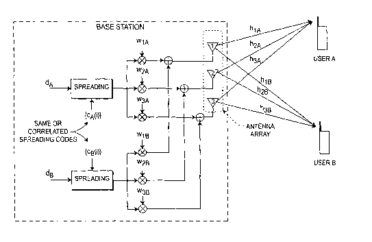
The number of users (USER A, USER B) and data (dA, dB) capacity of wireless
systems (Fig. 1) are increased by employing apparatus and method for
increasing the number of spreading codes (CA, CB) available in the system by
providing a mechanism to reuse the already allocated spreading code or use the
codes that may correlate to those already being used within the same
sector/cell. This, in return, provides capacity improvement proportional to
the number of added base station (BS) antennas (1, 2, 3) for each cell. An
antenna null steering technique for code allocation maintains the cross
correlation properties of the codes only for the desired user and to obtain a
gain in capacity improvement.
Le nombre d'utilisateurs (UTILISATEUR A, UTILISATEUR B) et de capacité de données (d<SB>A</SB>, d<SB>B</SB>) de systèmes sans fil (figure 1) augmente par l'utilisation d'un appareil et d'un procédé permettant d'augmenter le nombre de codes d'étalement (C<SB>A</SB>, C<SB>B</SB>), disponibles dans le système, par le biais d'un mécanisme permet de réutiliser le code d'étalement déjà attribué, ou d'utiliser les codes qui peuvent être corrélés à ceux déjà utilisés à l'intérieur du même secteur/cellule. Ceci, en retour, permet d'améliorer la capacité proportionnellement au nombre d'antennes (1, 2, 3) de station de base (BS) ajoutées pour chaque cellule. Une technique d'antenne non orientable pour attribution de code permet de maintenir les propriétés de trans-corrélation des codes uniquement pour l'utilisateur voulu et d'obtenir un gain au niveau de l'amélioration de la capacité.
Note: Claims are shown in the official language in which they were submitted.
Note: Descriptions are shown in the official language in which they were submitted.
2024-08-01:As part of the Next Generation Patents (NGP) transition, the Canadian Patents Database (CPD) now contains a more detailed Event History, which replicates the Event Log of our new back-office solution.
Please note that "Inactive:" events refers to events no longer in use in our new back-office solution.
For a clearer understanding of the status of the application/patent presented on this page, the site Disclaimer , as well as the definitions for Patent , Event History , Maintenance Fee and Payment History should be consulted.
| Description | Date |
|---|---|
| Inactive: IPC assigned | 2016-06-29 |
| Inactive: First IPC assigned | 2016-06-29 |
| Inactive: IPC removed | 2016-06-29 |
| Inactive: IPC removed | 2016-06-29 |
| Inactive: IPC removed | 2016-06-29 |
| Inactive: IPC expired | 2011-01-01 |
| Inactive: IPC removed | 2010-12-31 |
| Inactive: IPC expired | 2009-01-01 |
| Inactive: IPC removed | 2008-12-31 |
| Application Not Reinstated by Deadline | 2008-11-03 |
| Time Limit for Reversal Expired | 2008-11-03 |
| Deemed Abandoned - Failure to Respond to Maintenance Fee Notice | 2007-11-01 |
| Amendment Received - Voluntary Amendment | 2006-06-27 |
| Inactive: IPC from MCD | 2006-03-12 |
| Inactive: IPC from MCD | 2006-03-12 |
| Amendment Received - Voluntary Amendment | 2006-02-16 |
| Letter Sent | 2005-01-11 |
| Inactive: Single transfer | 2004-11-30 |
| Inactive: Courtesy letter - Evidence | 2004-06-29 |
| Inactive: Cover page published | 2004-06-27 |
| Inactive: Acknowledgment of national entry - RFE | 2004-06-22 |
| Letter Sent | 2004-06-22 |
| Application Received - PCT | 2004-06-04 |
| National Entry Requirements Determined Compliant | 2004-04-30 |
| Request for Examination Requirements Determined Compliant | 2004-04-30 |
| All Requirements for Examination Determined Compliant | 2004-04-30 |
| National Entry Requirements Determined Compliant | 2004-04-30 |
| Application Published (Open to Public Inspection) | 2003-05-15 |
| Abandonment Date | Reason | Reinstatement Date |
|---|---|---|
| 2007-11-01 |
The last payment was received on 2006-10-13
Note : If the full payment has not been received on or before the date indicated, a further fee may be required which may be one of the following
Please refer to the CIPO Patent Fees web page to see all current fee amounts.
| Fee Type | Anniversary Year | Due Date | Paid Date |
|---|---|---|---|
| Basic national fee - standard | 2004-04-30 | ||
| Request for examination - standard | 2004-04-30 | ||
| MF (application, 2nd anniv.) - standard | 02 | 2004-11-01 | 2004-10-15 |
| Registration of a document | 2004-11-30 | ||
| MF (application, 3rd anniv.) - standard | 03 | 2005-11-01 | 2005-10-18 |
| MF (application, 4th anniv.) - standard | 04 | 2006-11-01 | 2006-10-13 |
Note: Records showing the ownership history in alphabetical order.
| Current Owners on Record |
|---|
| INTERDIGITAL TECHNOLOGY CORPORATION |
| Past Owners on Record |
|---|
| LEONID KAZAKEVICH |
| NADER BOLOURCHI |
| RUI YANG |

