Note: Descriptions are shown in the official language in which they were submitted.
CA 02466384 2010-04-29
BUTT PLATE FOR FELLER BUNCHER
CROSS-REFERENCE TO RELATED APPLICATION
[0001] This application claims the benefit of provisional application Serial
No.
60/467,980 filed May 5, 2003, entitled "Butt Plate for Feller Buncher".
BACKGROUND OF THE INVENTION
FIELD OF THE INVENTION
[0002] This invention relates to forestry equipment, and in particular to a
butt plate for a
feller buncher for felling and accumulating trees.
DISCUSSION OF THE PRIOR ART
[0003] Felling heads are widely used in the logging industry for accumulating
several
freshly cut trees in a vertical position prior to laying down the bundle at
once, to be transported
to roadside by a skidder or forwarder. The felling head is mounted to a heavy
duty vehicle, such
as a drive to tree or swing to tree wheeled or tracked vehicle, for high
efficiency logging.
[0004] One type of felling head uses a large saw blade disc having peripheral
cutting
teeth. The disc is rotated in a horizontal plane below a butt plate, with the
teeth exposed at the
front of the butt plate. As successive trees are cut, harvesting arms are
actuated to pull the tree
into an accumulation pocket while at the same time an accumulation arm is
withdrawn from the
accumulation pocket and then moved behind or brought around the bundle of
accumulated trees
to add the newly cut tree to the bundle. See, for example, the prior art
felling head 10 which is
illustrated in Fig. 1.
[0005] In Fig. 1, a conventional butt plate 4 is provided over a disc saw 2
operated by a
motor 11. In this configuration, the butt plate 4 must be dimensioned to be
smaller than the saw
CA 02466384 2004-05-05
radius, limiting the size of the tree accumulation pocket to the small storage
area 5 on the butt
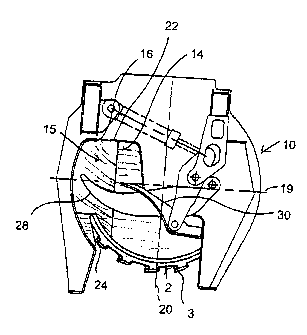
plate 4 itself. With this arrangement, trees can only be pushed rearwardly to
a limited degree,
and there is little space for tree storage, and essentially no space for a
separate accumulation
area, thereby limiting both the size and number of trees which can be
accumulated.
[0006] Because of these restrictions, various high accumulation butt plates
have been
developed. For example, butt plates have been developed to include angled
ramps which extend
over the saw blade to a plateau which provides a larger accumulation pocket,
allowing for the
accumulation of a larger number of trees and trees of a bigger size. Referring
to Figs. 2 and 3,
here a ramp 6 is provided between the butt plate 4 and a substantially flat
accumulation area 5.
The ramp 6 and accumulation area extend radially from an outer edge of the
disc saw 2 toward
the motor 11 at the center of the saw 2. The accumulation area 5 extends over
at least a portion
of the rim of the saw, and the bottom plate 30 of the accumulation area 5 is
elevated to achieve
this. When using this feller head, the trees are severed and then forced from
the butt plate 4, up
the ramp 6, and onto the elevated accumulation area 5 by a pivoted harvesting
arm. While these
butt plates provide a large accumulator, they are difficult to construct as
they require multiple
bends, machining, bolting and/or welding of the butt plate 4 and ramp 6, as
shown in Fig. 3.
Furthermore, because the ramp 6 extends radially from the edge of the saw to
the motor 11, all
accumulated trees must be forced up the ramp 6 to the accumulation area 5.
Accumulating trees,
therefore, requires a significant degree of force and energy. Additionally,
because the
accumulation area is flat, once the trees are severed and provided on the
accumulation area, they
are difficult to keep straight and can slide back and forth on the
accumulation plate. Bundles of
accumulated trees, therefore, are not stable in the accumulator pocket and can
shift during
operation.
(T01281-0004-C.4)
TDO-RED #8229814 i.1 -2-
CA 02466384 2004-05-05
[0007] There remains a need, therefore, for a high accumulation butt plate
which is easy
and inexpensive to manufacture and which can easily accumulate trees while
exerting a limited
amount of force and energy.
SUMMARY OF THE INVENTION
[0008] In one aspect, the present invention provides a felling head for a
feller buncher
including a housing, a disc saw blade having a disc and teeth at an outer
perimeter of the disc,
and a motor, mounted in the housing that drives the disc saw blade with teeth
of the blade being
exposed in a severance area at the front of the housing. The housing includes
a butt plate that is
mounted over the disc saw blade that has a severance area portion behind the
severance area at
the teeth and is generally parallel to the blade. A portion of the
accumulation area is angled
upward to provide an accumulation area that is sloped upward from the
severance area at the butt
plate to an outer edge of the butt plate. At least one arm is moveably coupled
over the butt plate
to move a tree severed by the disc saw into the accumulation area and to
maintain the severed
tree in the accumulation area. The severed trees held in the accumulation area
are each
supported from an outer edge of a butt of each tree so that the trees lean
inward relative to the
felling head.
[0009] In one embodiment, the butt plate is upwardly angled along a line
extending from
a first point adjacent the outer circumference of the butt plate to a second
point on an inner edge
of the butt plate. In another embodiment, the butt plate is angled along a
line parallel to a
machine direction of the felling head. In yet another embodiment, the butt
plate is angled along
a first line extending from a front portion of the butt plate rearwardly in
one direction and along a
second line extending from the first line in a different direction to the back
of the butt plate. A
vertically-extending back plate is provided along the sides of the sloping
accumulation pocket,
(T01281-0004-C'A)
TDO-RED #8224814 r. 1 -3 -
CA 02466384 2004-05-05
wherein the accumulated trees are supported in the sloping accumulation pocket
from an outer
edge of a butt end of each tree and tend to lean inwardly, preferably toward
the vertically
extending back plate
[0010] In another aspect of the invention, a felling head for a feller buncher
is provided.
The felling head includes a saw housing securable to a logging vehicle, a disc
saw blade
mounted in the saw housing and having an exposed front portion in a severance
area of the
housing, and a motor, centered in the saw housing for turning the disc saw
blade. A butt plate
mounted in the saw housing over the disc saw blade is generally parallel to
the blade, and
includes a portion that is angled upward from the severance area to an outer
edge of the butt plate
to form a sloping accumulation pocket for supporting accumulated trees from an
outer edge of a
butt end of each tree supported on the sloping accumulation pocket.
The butt plate can include a debris plate that is coupled beneath the
downwardly sloping
accumulation pocket in the portion that extends radially beyond the teeth of
the saw blade at an
entry of the teeth into the saw housing to limit debris from entering the saw
housing.
The debris plate preferably has a surface that is sloped at the same angle as
the accumulation
pocket, and can also include a channel over the teeth of the saw blade to
provide clearance
between the debris deflector and the teeth of the saw blade. A check plate can
also be provided
between the saw blade and the housing to prevent deflection of the saw blade
that would result in
teeth of the saw blade impacting the housing.
[0011] To limit the entry of debris into the saw housing, the angled portion
of the butt
plate can be directed along a line along the butt plate selected to direct the
flow of chips and
debris to exhaust the chips through the saw housing. The saw housing can also
include a
(TO! 28 / -0004-C A )
TDO-RED #82229814 v.1 -4-
CA 02466384 2004-05-05
backplate extending vertically from a back section and opposing side sections
of the
accumulation pocket to provide a surface against which accumulated trees can
rest.
[0012] In another aspect of the invention, a butt plate is provided including
a toroidal
section having an outer circumference sized and dimensioned to extend over a
portion of a disc
saw blade while maintaining the teeth of the disc saw blade exposed and an
inner circumference
sized and dimensioned to receive a motor, and an accumulation section,
extending laterally from
the toroidal section. The accumulation section includes a ramp angling
upwardly along a line
drawn through the accumulation section from a first point adjacent the teeth
of the disc saw blade
to a second point on an opposing side of the butt plate to an outer edge of
the butt plate.
[0013] These and other objects and advantages of the invention will be
apparent from the
drawings and detailed description.
BRIEF DESCRIPTION OF THE DRAWINGS
[0014] Fig. 1 is a top plan view of a prior art felling head;
[0015] Fig. 2 is a top plan view of a prior art felling head with a high
accumulation butt
plate;
[0016] Fig. 3 is a cutaway view of the felling head of Fig. 2 taken along line
3-3;
[0017] Fig. 4 is a perspective view of a butt plate constructed in accordance
with the
present invention;
[0018] Fig. 5 is a top plan view of the butt plate of Fig. 4, prior to
bending;
[0019] Fig. 6 is a side view of the butt plate of Fig. 4, viewed in the
direction of the bend
line;
[0020] Fig. 7 is a top plan view of a felling head of the present invention
incorporating
the butt plate of Fig. 4;
(T01281-0004-C'A)
TDO-RED #8229814 i'.1 -5-
CA 02466384 2004-05-05
[0021] Fig. 8 is a perspective view of a second embodiment of a butt plate
constructed in
accordance with the present invention;
[0022] Fig. 9 is a top plan view of the butt plate of Fig. 8, prior to
bending;
[0023] Fig. 10 is a side view of the butt plate of Fig. 8, viewed in the
direction f the bend
line;
[0024] Fig. 11 is a top plan view of a felling head of the present invention
incorporating
the butt plate of Fig. 8;
[0025] Fig. 12 is a bottom view of the felling head of Fig. 11 showing a check
plate and
debris plate coupled to the underside of the ramped portion of the
accumulation area;
[0026] Fig. 13 is a fragmentary cross-sectional view taken along the line 13-
13 of Fig.
11;
[0027] Fig. 14 is a top view of the debris deflector plate of Fig. 11;
[0028] Fig. 15 is a side view of the debris deflector plate of Fig. 14;
[0029] Fig. 16 is a perspective view of the felling head of Fig. 11;
[0030] Fig. 17 is a bottom view of the felling head of Fig. 11 illustrating a
rear exhaust;
[0031] Fig. 18 is a front perspective view of the felling head of Fig. 11
illustrating an
additional wood chip exhaust point;
[0032] Fig. 19 is a top view of the felling head of Fig. 11 with the
accumulation pockets
full;
[0033] Fig. 20 is a cutaway view of the felling head of Fig. 19 taken along
the line 20-20
of Fig. 19;
[0034] Fig. 21 is a top view of a felling head with a butt plate constructed
in accordance
with a third embodiment of the invention; and
(TO/281-0004-C'A)
TDO-RED #8229814 r. / -6-
CA 02466384 2004-05-05
[0035] Fig. 22 is a side view of the felling head of Fig. 19, illustrating a
debris and check
plate.
DETAILED DESCRIPTION OF THE PREFERRED EMBODIMENT
[0036] Referring now to the figures and more particularly to Fig. 4, a butt
plate 12
constructed in accordance with the present invention is shown. The butt plate
12 comprises a
first generally toroidal section 13, or severance area of the butt plate, that
is sized and
dimensioned to fit inside the teeth 3 of an underlying saw blade 2, and an
accumulation pocket
15 extending laterally beyond the teeth of the saw blade 2 and rearwardly
behind the exposed
teeth 3 of the saw blade 2 to provide an accumulation area for accumulating
severed trees. As
shown here, the accumulation area 15 comprises both a flat planar portion 14
and a ramped
portion 16, where the ramped portion 16 extends from a bend line 22 in the
butt plate 12 to the
outer edge of the butt plate 12.
[0037] Referring still to Fig. 4, the butt plate 12 includes a front edge 40,
a back edge 42,
and left and right side edges 46 and 48, where left and right are determined
as looking into the
front of a felling head. The front edge of the butt plate 12 includes a curved
section 33, sized and
dimensioned to fit inside of the teeth 3 of disc-shaped saw blade 2 (Figs. 1,
2) as described
above, and a laterally-extending section 17. The curved section 33 extends
from the right side
edge 48 toward a transition point 49, at which the exposed teeth 3 enter a saw
housing. From the
transition point 49, therefore, it is no longer necessary to expose the teeth
3 for severing trees,
and, from this point, the laterally extending section 17 angles forward and
toward the left side
edge 46, away from the curved section 33, forming a triangular section 24 at
the front of the butt
plate which, in use, extends over and beyond the teeth 3 of the saw blade 2,
to reduce the space
above and outside of the teeth 3. The back edge 44 includes an inner radial
curve 18, a
(T0128/-0004-C'A)
TDO-RED #8229814 v.1 -7-
CA 02466384 2004-05-05
rearwardly-extending linear section 21, and a laterally-extending linear
section 45. The inner
radial curve 18 is sized and dimensioned to receive a motor 11 (Fig. 1, 2).
The rearwardly
extending linear section 21 extends away from the inner radial curve 18
substantially parallel to a
center line 20 in the machine direction, and back beyond a lateral center line
19 through the
machine, while the laterally-extending section 45, extends substantially
perpendicularly to the
linear section 21 toward the left side 46. The left side 46 is curved to mate
with a saw housing
as described below, and extends from the lateral straight section 45 in the
back edge 44 to the
laterally extending section 17 of the front edge 40. The right side 48 extends
from the curved
section 33 of the front edge 40 to the curved section 18 of the back edge 42
and can, as shown
here, be curved or angled toward the back edge 42.
[0038] The curve 33 of the front edge 40 and the curve 18 of the back edge 42
together
form the generally toroidal section 13 which is positioned over the saw blade
2. The
accumulation pocket 15 is positioned laterally of the toroidal section 13 and
includes the area
formed between the laterally extending section 17 of the front edge 40, the
linearly extending
portion 21 of the back edge 42, the left side 46, and the lateral straight
section 45 of the back
edge. The accumulation pocket 15 therefore provides an area which extends over
the teeth 3 of
the saw blade 2 for accumulating trees. The accumulation pocket 15 further
includes a bend line
22 which is offset from and substantially parallel to the machine direction
line 20, and hence to
the vertical center line 20 of the felling head 10 and saw blade 2 as drawn
along the machine
direction.
[0039] Referring now to Fig. 5, the butt plate 12 of Fig. 4 is constructed
from
substantially flat metal plate 28. The angled portion 16 is constructed by
bending the
accumulation pocket 15 front to back along the bend line 22 or by welding two
substantially flat
(T01281-0004-(A)
TDO-RED #82298/4 v. I - 8 -
CA 02466384 2004-05-05
plates at an angle (e.g., 20 ). As described above, the bend line 22 is
substantially parallel to the
machine direction line 20 of the saw blade 2, typically the direction that
trees are fed into the
felling head 10 as shown in Fig. 2. A second bend, along bend line 26, returns
the edge 24 of the
small triangular area that borders line 26 to a horizontal plane substantially
parallel to the planar
portion 14. This corner is bent down to ease the accumulating of larger
diameter trees, so the
head can handle a broader range of tree sizes.
[0040] Referring now to Fig. 6, a side view of the butt plate 12 of Fig. 4 is
shown. As
can be seen here the butt plate 12 is horizontally planar through the toroidal
section 13 and the
flat planar portion bordered by line 26 and edge 24 of the accumulation pocket
15. The ramp
portion 16 begins at the bend line 22, and as shown here, extends up at an
angle of approximately
20 degrees to the horizontal planar surface of the butt plate 12, and
continues at an upward slope
to the outer edge of the butt plate 12.
[0041] Referring now to Fig. 7, a felling head 10 constructed to include the
butt plate 12
of Fig. 1 is shown. As can be seen in Fig. 7, the butt plate 12 is provided in
a saw housing 29
and positioned such that the toroidal portion 13 is provided over the saw 2
allowing the teeth 3 to
extend radially therefrom and therefore be exposed at the severance area of
the housing 29. The
accumulation pocket 15 extends rearward beyond a lateral center line 19 of the
saw
(perpendicular to the machine direction), and includes the ramped portion 16
which, as described
above, extends in a direction laterally offset from but substantially parallel
to a longitudinal
center line 20 of the saw 2 in the machine direction. A harvesting arm 28 and
an accumulation
arm 30 are pivotally mounted over the butt plate 12 for moving severed trees
from the severance
area in which the blade is exposed for cutting that extends to each side of
longitudinal center line
20 and to the accumulation pocket 15, and for retaining accumulated trees
therein.
(T01281-0004-C'A)
TDO-RED #8229814 . I -9-
CA 02466384 2004-05-05
[0042] Trees are fed into the felling head 10 in the machine direction as
defined by the
line 20. As a tree is cut it is accumulated initially in the flat portion 14
of the accumulation area
15, therefore requiring very little applied force from harvesting arm 28 to
accumulate the tree
into the accumulation pocket 15. As additional trees are accumulated,
harvesting and
accumulator arms 28 and 30 are activated to force the tree up the ramp portion
16 providing
additional storage for the trees. The ramped portion 16 encourages accumulated
trees to lean and
slide inward, generally toward the center of the saw blade 2, thereby keeping
the trees both
straight and neatly bunched during accumulation. Only when there is
insufficient room on the
lower level 14 of the butt plate for additional trees are trees forced up the
ramp 16.
[0043] Referring now to Fig. 8, a butt plate 12 constructed in accordance with
a second
embodiment of the invention is shown. Here, again, the butt plate 12 comprises
a first generally
toroidal section 13 and an accumulation pocket 15 which includes a ramped
portion 16, and is
constructed generally as described above with reference to Fig. 4. Here,
however, rather than
extending parallel to the longitudinal center line 20 drawn in the machine
direction (i.e. the
direction of straight line forward travel of the machine to which the head is
attached), the bend
line 42 is angled across the butt plate 12, extending from a first point on
the curved portion 33 of
the front edge 40 of the butt plate 12 and offset from the center line 20 to a
second point on the
linear portion 21 of the back edge 44 of the butt plate 12, which is offset
from but relatively
closer to the center line 20, such that the bend line 42 angles toward the
center line 20 as it
moves from the front of the butt plate 12 toward the back of the butt plate
12, so as not to choke
off the open area around the blade downstream of the severance area. As
described above, the
outer circumference of the toroidal area 13 is sized and dimensioned to extend
over a saw blade
2, while allowing the teeth 3 to extend radially beyond the butt plate 12 in
the severance area.
(T01281-0004-CA)
TDO-RED #8229814 n. ! - 10-
CA 02466384 2004-05-05
The accumulation area 15, however, extends radially, laterally and rearwardly
beyond the
toroidal section to provide a larger area for accumulating trees.
[0044] Referring now to Fig. 9, as described above with reference to Fig. 5,
the butt plate
12 is constructed from a substantially flat metal plate 28. The angled portion
16 of the
accumulation pocket 15 is constructed by bending the flat metal plate 28
upward along the bend
line 42 or welding two plates at an angle. Also as described above, the bend
line 42 is angled
with respect to the vertical center line 20 of the saw blade 2. Referring now
to Fig. 10, a side
view of the butt plate 12 of Fig. 8 is shown. As can be seen here, the butt
plate 12 is horizontally
planar through the toroidal section 13. The ramp portion 16 begins at the bend
line 42 and
extends up at an angle of approximately fifteen degrees to the horizontal
planar surface of the
butt plate 12, and continues sloping upward to the outer edge of the butt
plate 12.
[0045] Referring now to Fig. 11, a felling head 10 constructed to include the
butt plate 12
of Fig. 8 is shown. The felling head 10 includes a saw housing 29 in which the
saw blade 2 and
butt plate 12 are mounted. The butt plate 12 is again mounted above the saw
blade 2 such that
the toroidal portion 13 is provided over the saw 2 allowing the teeth 3 of the
saw 2 to extend
radially beyond the butt plate 12 in the severance area. The accumulation
pocket 15 extends
laterally beyond the teeth 3 of the saw blade 2, and includes the ramped
portion 16 which, as
described above, angles from a first point on the curved outer edge 33 of the
butt plate 12 to a
second point on the linear portion 21 of the back edge 44 of the butt plate
12, and therefore
generally toward the center line 20 of the felling head 10. The bend line 42
provides an
accumulation pocket 15 including both an angled portion 16 which extends from
the bend line 42
to an outer edge of the butt plate, and a small flat portion 14. A harvesting
arm 28 and an
accumulation arm 30 are pivotally mounted over the butt plate 12 for moving
severed trees from
(T01281-0004-C'A)
TDO-RED #8229814
CA 02466384 2004-05-05
the severance area of the butt plate 12 which extends on each side of line 20,
to the ramped
portion 16 of accumulation pocket 15, and for retaining accumulated trees
thereon. Referring
now to Fig. 12, the severed trees are retained on the ramped portion 16 of the
accumulator pocket
15, and are held in position by the accumulator arm 30. Because the plate 16
is angled
downwardly toward the center line 20, the severed trees are aligned and stable
in the pocket.
Referring again to Fig. 11, a debris plate 34 is coupled beneath the angled
portion 16 of the butt
plate 12 to prevent wood chips and debris from entering the saw housing 29, as
described below.
[0046] Referring now to Fig. 12, a partial bottom view of the felling head 10
of Fig. 11 is
shown illustrating the debris plate 34 and a check plate 32. The debris plate
34 is welded or
otherwise coupled beneath the butt plate 12 adjacent to the transition point
49 between the
curved section 33 and the laterally-extending section 17 of the front edge 40
of the butt plate 12
where the exposed teeth 3 of the saw blade 2 enter the saw housing 29, and
therefore where
wood chips and debris are most likely to enter the saw housing 29. Referring
now also to Fig.
13, the debris deflector plate 34 is a six-sided plate. A first side 60 is
curved at the radius of
curvature of the saw housing 29 to allow the debris plate 34 to abut the saw
housing 29. The
sides 66, 68, and 70 are sized, dimensioned and angled to follow the corner
formed between
transition point 49 between the curved portion 33 of the front edge 40 of the
butt plate 12 and the
laterally extending portion 17. The side 76 extends linearly from the side 70
to the side 74,
which extends forward and angles toward the curved side 60. A channel 38 is
formed in the
bottom of the debris plate 34 between a first line 62 and a second line 64.
When in position
coupled to the butt plate 12, the side 70 extends from a point on the curved
portion 33 of the
front edge of the butt plate 33 offset toward the center line 20 from the
transition point 49 to an
endpoint position near the saw housing 29, and the side 74 angles from the
endpoint of the side
(TO1281-0004-('A)
TDO-RED #8229814 v.1 -12-
CA 02466384 2010-04-29
76 toward the saw housing 29, thereby substantially closing off the area
beneath the butt plate 12
and between the saw blade 3 and the saw housing 29 from the exposed front area
of the saw
blade 2. Referring now also to Fig. 14, the debris deflector plate 34 is
sloped down from the line
72 toward the side 76 at an angle selected to be substantially the same as the
angle of the bend at
the bend line 42 which, here, is fifteen degrees.
[0047] Referring now also to Fig. 13, a cutaway view of the felling head 10
taken along
the line 13 - 13 of Fig. 11 is shown. As described above, the debris plate 34
is coupled, and
preferably welded, beneath the butt plate 12 and, when provided in the felling
head 10, is
positioned between the plate 12 and the saw blade 2. The bottom of the debris
deflector plate 34
is, as described above, machined to provide a channel 38 which prevents the
debris deflector
plate 34 from contacting and damaging the teeth 3 of the saw blade 2. As
described above, the
debris deflection plate 34 is wedge-shaped, and angles down to close the gap
between the butt
plate 12 and saw blade 3 to inhibit plugging of the housing by wood chips or
other debris.
[0048] Referring again to Fig. 12, the check plate 32 extends behind the
debris deflection
plate 34, substantially following the angle of the curve 33 of the front edge
40 of the butt plate
12, and is welded or otherwise coupled to the underside of the butt plate 12
at the transition point
49 where the saw blade 2 moves under the butt plate 12. The check plate 32
prevents the saw
blade 12 from deflecting into the butt plate 12, and therefore limits the
possibility of damaging
the teeth 3 of the saw blade 2.
[0049] Referring now to Figs. 16 - 18, the felling head 10 further manages the
flow of
wood chips and debris through the saw housing as described more fully in U.S.
Patent Numbers
6,068,035 and 6,176,280. Here, as trees are accumulated, wood chips and debris
are exhausted
from the saw
-13-
CA 02466384 2004-05-05
housing in a number of locations. First, referring to Fig. 16, the debris
plate 34 provided beneath
the butt plate 12 limits or prevents wood chips and debris from entering the
saw housing 29.
Referring now to Fig. 17, the angle of the bend line 42 across the butt plate
12, furthermore, is
selected to direct the flow of wood chips and debris around the saw housing
29, toward a
secondary exhaust point 80 provided at the back of the saw housing 29. Wood
chips and other
debris which is not exhausted through the back of the housing 29 follow the
flow of the saw
blade 2 to an exit aperture 82 provided on the right hand side of the saw
housing 29. By
providing a path for wood chips and debris which promotes a flow of chips
toward exhaust areas
in the saw housing 29, the potential for plugging the saw housing 29 with wood
chips or other
debris is limited.
[0050] Referring again to Fig. 16 and also to Figs. 19 and 20, it can be seen
that the saw
housing 29 includes substantially vertical backing plates 86, 87, and 88 which
surround the
accumulation area 15, extending upwardly from the linearly extending portion
21 of the back
edge 44 of the butt plate, the laterally extending portion 45 of the back edge
44 of the butt plate
12, and the left edge 46 of the butt plate 12, respectively. The backing
plates 86, 87, and 88
therefore provide a walled structure surrounding the accumulation pocket 15.
Referring now
specifically to Fig. 19, as trees are harvested by the harvesting arm 28, they
are accumulated into
the accumulation pocket 15, and the accumulation arm 30 maintains the trees in
the
accumulation pocket 15. Referring now also to Fig. 20, as trees are
accumulated in the pocket
15, they are maintained in a substantially balanced, upright position against
the ramped portion
16 of the pocket 15. Trees supported on ramped portion 16 are supported by an
outer edge of the
butt of the tree, and the inner edge is unsupported, so that the trees lean
inward, generally toward
the backing plate 86 adjacent the longitudinal center plane of the disc saw.
The trees, therefore,
(TO / 281-0004-C'A)
TDO-RED #82298/4 v.1 -14-
CA 02466384 2004-05-05
are more stable in the accumulation pocket as compared to the prior art, and
are maintained in a
straighter bundle which is easier to handle. Although the backing plates 86,
87, and 88 are
shown and described specifically with reference to the embodiment of Fig. 11,
it will be apparent
that the saw housing 29 and the stacking would be similar for the first
embodiment of the
invention shown in Fig. 4, and the third embodiment described below.
[0051] Referring now to Fig 21, a third embodiment of a feller head 10
including a butt
plate 52 is shown. The butt plate 52 is again constructed from a flat piece of
material 28
generally as described above. Here, however, the ramped portion 16 of the
accumulation pocket
15 is formed with two bends 54 and 56. The bends 54 and 56 are formed in the
accumulation
pocket 15 along the circumference of the butt plate 12. The first bend 54 is
formed extending
from the exposed front at the butt plate to about the horizontal center line
19, and generally
follows the curve of the outer circumference of the butt plate 12. The second
bend 56 extends
from the end point of the first bend, at the approximate horizontal center
point 19 toward the
back of the butt plate 12, again substantially following the curve of the
circumference of the butt
plate 12. The double bend including bends 54 and 56 therefore substantially
follow the outer
circumference of the butt plate from front to back.
[0052] Referring now to Fig. 22, a view looking forward into the front of the
felling head
is shown. Here, a check plate 32 and debris plate 34 are preferably coupled
under the ramped
section 16. The check plate 32, as described above, limits motion of the saw
blade 2 to prevent
deflection into the butt plate 12. The debris plate 34 inhibits debris from
entering the saw
housing 29. As described above, the debris plate 34 can also be sloped
downward, toward the
front of the felling head 10 and/or sharpened to provide a blade for cutting
through debris (wood
chips). Furthermore, as described above with reference to the bend line 42,
the double bend
(T01281-0004-CA)
TDO-RED #8229814 v.1 - 15 -
CA 02466384 2004-05-05
provided by bend lines 54 and 56 provides a ramp 16 which directs debris and
wood chips in the
saw housing 29 around the saw housing 29 to an exit side to prevent plugging.
As described
above, the form of the ramp 16 here is selected to direct debris and wood
chips around and out of
the saw housing 29.
[0053] Although a number of specific embodiments have been shown, it will be
apparent
that variations can be made within the scope of the invention. For example,
although specific
ramping bend patterns have been shown, it will be apparent that various angles
directed
generally toward the center of the felling head can also be used. Furthermore,
although the
method of forming the ramped section is described as bending the butt plate
along a bend line,
various other methods of forming a ramp, such as welding pieces together at an
angle, could also
be used.
[0054] A preferred embodiment of the invention has been shown and described in
detail.
Many modifications and variations of the embodiment described will be apparent
to those skilled
in the art. For example, various mechanisms may be used to power the inner and
outer arms
opened and closed. Therefore, the invention is not limited to the embodiment
described.
(T01281-0004-CA)
TDO-RED #8229814 >>.1 - 16-