Note: Descriptions are shown in the official language in which they were submitted.
CA 02466569 2004-05-28
ENCODER FOR DIGITAL DATA STORAGE
Backoround of the Invention
Field of the Invention
The present invention relates to a system and method for encoding data for
storage on a magnetic or other
data storage media and, in particular, to a variable rate bit insertion
encoding system and method.
Description of the Related Art
Variable-rate b'rt insertion techniques are well known as a method for making
a data stream robust against
the detection of possible errors in the data stream. Typically, this method
has application in the communication field,
although variable rate bit insertion has been used in other applications, as
is well known in the art. According to
this technique, data bits are inserted into selected portions of a data stream
where there is an increased likelihood
that an error will be made in detecting the data bits accurately at this
portion of the data stream. For example,
variable-rate bit insertion may be used in a communications system where the
receiving decoder is self-clocked. It
is important that long strings of ones or zeros be broken up so that the phase
locked loop at the detector side does
not lose phase lock on the clock rate at which the data is being transmitted.
This is particularly important in
applications involving reading, for example, from magnetic tape since tape
storage media typically have a very
uncertain speed profile so that frequent clocking information is preferable to
maintain phase lock. Thus, in such
applications where it is desirable to maintain phase lock at the reading or
receiving side, data bits are intentionally
inserted into "trouble regions" within the output data stream so that at the
detector side, sufficient information is
present in the received data signal to maintain accurate phase lock on this
data signal so that the data stream can
ZO be properly decoded.
Although the method of variable-rate bit insertion is desirable as an
inexpensive and fairly simple method
of increasing the robustness of data against errors, such a method has
typically been found to be impractical in other
applications. Most notably, variable-rate bit insertion has had fim'rted
applicability in the magnetic recording
environment. Magnetic recording typically involves storage onto a tape or a
disk, where data is stored to the
magnetic tape or disk first and then read back. To provide for robust storage
of data, variable rate bit insertion
might be used to encode the data before wr'tting to the magnetic media, and
when the data is read back, the
inserted bits would be detected and discarded. However, since the actual
number of bits which are to be inserted
is highly unprEdictable, it is possible that the number of bits inserted would
extend the length of the data stream
by as much as 10 to 12 percent. Such: an extension of the data stream is
unacceptable for purposes of data
storage, especially when it is desirable to maximize data storage efficiency.
For example, 'rf a particular data stream
has characteristics such that a bit insertion is called for every 10 b'tts,
then the amount of data to be stored onto
the magnetic media will increase by 10 percent. This effect'nely makes a 500-
megabyte storage media into a
450-megabyte storage media.
In an effort to transform the data stream into a form that is amenable to
variable-rate bit insertion, the
incoming data stream is first randomized using, for example, a pseudo-random
noise code which is exclusive ORed
with the incoming data stream to give the resulting output a random or pseudo-
random character. This random
CA 02466569 2004-05-28
.2.
character ensures that the probability of a data stream of being extended by
mare than 1 percent, for example, is
statistically negligible. This is because bit insertion is typically performed
to break-up regular patterns so that a
substantially random pattern will require very few bit insertions. Thus, by
randomizing the data before applying the
variabb-rate bit insertion techniques, such techniques can be more readily .
applied in applications involving data
storage on magnetic or other data storage media.
It has been found, however, that in certain instances, when the incoming data
pattern has a characteristic
that correlates with the pseudo noise code (i.e., the randomiser potynomiall
in such a way as to produce undesirable
encoded characteristics (e.g., bng strogs of ones or zeros, or other redundant
patterns, the randomization of the
data stream using that particular randomizing polynomial does not act to
prevent the bngth of the inserted data bits '
from being prohibitively long. A data stream having this characteristic is
typically referred to to a degenerate
pattern. Thus, when the incoming data stream is degenerate, variable-rate b'rt
insertion techniques ere not practical
for use with magnetic storage or other data storage mesa. Furthermore, simply
the poss~g'rty of such a degenerate
data pattern has generally been considered as an impediment to the use of
variabb-rate bit insertion in the data
storage enveonment.
in addition to the aforementioned shortcomings of variable-rate bit insertion
in the data storage applications,
it has been found that conventanal technpues of variable-rate bit insertion do
not always ensure that errors on the
receive side associated with loss of phase information and automatic gain
control are alleviated. For krstence, if a
detected data stream has characteristics such that a maximum swing in
amplitude is not observed for a bng period
of time, this can cause the automatic gain control at the detection side to
lose tracking, thereby introducing
amplitude errors into the detected signal. Furthermore, bss of phase lock may
result from data patterns other than
consecutive strings of zeros and ones. Accordingly, simply inserting a bit in
long strings of zeros and ones does rrot
ensure that phase lock wiA be maintained in a self-clocking system at the
decoding side. Thus, a need exists for
an improved data encoding method which resohres the difficulties associated
with variable-rate bit insertion in data
storage applications and also accounts for receive-side errors associated with
miscaibration of the automatic pain
control or phase lock loop.
Summary of the Invention
A system and method of data coding in accordance with the teachings of the
preferred embodiment of the
invention alleviates the aforementioned shortcomings associated with variable-
rate bit insertion in data storage
applications. In accordance with the present invention, rather than inserting
only a single data bit during a
variable-rate bit insertion technique, multipb bits that encode maximum phase
and amplitude information are inserted
into the data stream so that the informat'ron necessary for maintaining phase
lock and for properly cal'~bratinp the
automatic gain control during the read operation is always present within the
recorded data stream. According to
a particularly advantageous embodiment of this invention, four data bits are
inserted upon each detection of a
"troubb region" of the date stream.
In a preferred embodiment, the method of variable-rate bit insertion is
combbed whh a configurable
randomizer so that if it is determined that a particular pseudo-random
randomizing code produces a degenerate data
CA 02466569 2004-05-28
-3-
pattern, the randomizing polynomial can be reinitialized so that the
randomizer is reconfigured. It has been
found that if one pseudo-noise code produces a degenerate pattern, then
another which is orthogonal to it, such
as one in the same family, will not result in a degenerate data pattern. Thus,
in a preferred embodiment, the
reconfiguration of the randomizer to an orthogonal code ensures that a
degenerate data pattern will not be
produced by the randomizer.
In a particularly advantageous embodiment of this aspect of the invention, the
randomizing
polynomials are reinitialized according to a non-deterministic method so that
the reconfiguration of the
randomizer is not easily predictable, This aspect of the preferred embodiment
of the invention counteracts data
streams which are specifically designed with the intent of producing a
degenerate data pattern.
According to another aspect of the invention, the configuration of the
randomizer is capable of being
altered on a block-by-block basis so that the randomizer configuration can be
changed "on the fly".
According to another aspect of the invention there is provided an apparatus
for encoding a digital
data stream to be stored onto a data storage medium, said apparatus
comprising: a randomizer seed selector
configured to non-deterministically select a randomizer seed; a pseudo-noise
code generator receiving said
randomizer seed which is configured to output a pseudo-noise code defined at
least in part by said randomizer
seed; a logic circuit receiving at least a selected portion of said digital
data stream and said output of said
pseudo-noise code generator, wherein said logic circuit is configured to
combine said digital data stream and
said output of said pseudo-noise code generator to form a randomized digital
data stream for storing onto said
data storage medium.
According to another aspect of the invention there is provided a method of
storing data onto a data
storage medium comprising the steps of: non-deterministically selecting a
randomizer seed; randomizing a
plurality of bits using a pseudo-noise code defined at least in part by said
randomizer seed; storing said
randomized plurality of bits onto said data storage medium; and storing said
randomizer seed onto said data
storage medium so that said randomizer seed is available for subsequent
retrieval and de-randomization of said
plurality of bits.
According to another aspect of the invention there is provided a method of
recording and retrieving
data comprising the steps of: randomizing a first block of data with a first
non-deterministically selected
randomizer code to produce a first randomized block of data; storing said
first randomized block of data and
said first non-deterministically selected randomizer code onto a magnetic
media; randomizing a second block of
data with a second, different non-deterministically selected randomizer code
to produce a second randomized
block of data; storing said second randomized block of data and said second
non-deterministically selected
randomizer code onto said magnetic media; and retrieving said first randomized
block of data from said
magnetic media; retrieving said first non-deterministically selected
randomizer code from said magnetic media;
de-randomizing said first block of data with said first non-deterministically
selected randomizer code; retrieving
said second randomized block of data from said magnetic media; retrieving said
second non-deterministically
selected randomizer code from said magnetic media; de-randomizing said second
block of data with said second
CA 02466569 2004-05-28
-3a-
non-deterministically selected randomizer code.
According to another aspect of the invention there is provided a method of
storing digital data
comprising: non-deterministically defining a data randomization process;
randomizing a block of data using said
data randomization process to produce a randomized block of data; storing said
randomized block of data onto
a data storage medium, and in association therewith, storing information
regarding said non-deterministically
defined data randomization process, wherein said information allows de-
randomization of said randomized block
of data when said randomized block of data and said information are retrieved
from said data storage medium.
Brief Description of the Drawings
Figures 1 a and 1 b are overall system diagrams that illustrate exemplary
embodiments of a data
encoder and a data decoder system, respectively, for coding data to be stored
on a data storage media and
decoding data which is read from the data storage media.
Figure 2 is a simplified block diagram that illustrates the main functional
elements of the
randomizer/bit insertion encoder of Figure 1a.
Figure 3 is a simplified block diagram that illustrates the main functional
elements of the
derandomizer/bit extractor decoder of Figure 1 b.
Figure 4 is a flowchart that illustrates the general method used to insert a
data bit pattern in
accordance with the variable-rate encoding method of the present invention.
Figure 5 is a flowchart that illustrates a submethod used to determine the
null metric within the null
metric subroutine block of Figure 4.
Figure 6 is a flowchart that illustrates the general method used in accordance
with the present
invention to determine the automatic gain control metric within the gain
control metric subroutine block of Figure
4.
Figure 7 is a flowchart that illustrates the method used in accordance with
the present invention to
determine the phase metric within the phase metric subroutine block of Figure
4.
Figure 8 is a flowchart that illustrates the submethod used within the insert
bit pattern subroutine
block of Figure 4 to select and insert the appropriate bit pattern into the
input data stream.
Figure 9 is a flowchart that illustrates a general method used in accordance
with the present invention
to reconfigure the randomizer polynomial when data is to be stored to a
magnetic disk.
Figure 10 is a flowchart that illustrates the overall method used in
accordance with the present
invention to reconfigure the randomizer polynomial when the data storage media
written to is a magnetic tape.
Figure 11 schematically illustrates the format of a data block in one
preferred embodiment of the
invention.
Figures 12-12d schematically illustrate the method used within a convolutional
encoder to simulate
the read-head impulse response in order to determine the null, phase, and
automatic gain control metrics.
CA 02466569 2004-05-28
.Q.
Detailed Description of the Preferred~mbodiment
Figure 1a is a highly simplified schematic black diagram that illustrates an
exemplary data encoder system
for use in encoding a data input stream for storage on a data storage media.
As depicted in Figure 1a, the system
100 includes a Reed-Solomon encoder 105, which receives the data input stream
from a direct memory access (DMA)
channel 102, which manages the flow of data in and out of the shared memory
resources. Reed-Solomon encoding
is well known in the art, and will not be described in detai herein.
Furthermore, it wdl be appreciated by those of
ordinary skill in the art that the data input stream need not be encoded by a
Reed-Solomon encoder. In practice,
other forms of error encoding, such as treks encoding, convolutbnal encoding,
etc., may be used in the system of
Figure 1a as called for by the specific application. Once the data has been
Reed-Solomon encoded within the
Reed-Solomon encoder 105, the data is block interleaved within a block
interleaver 110. As is wag known in the
art, a block inter(eaver typically comprises a matrix wherein the data stream
is fed in by rows and read out by
columns. By bbck interleaving the encoded data, errors which occur during a
deep fade (i.e., when a long succession
of data is lost due to Rayleigh fading effects) are distributed in smaNer
chunks throughout a larger portion of the
data input stream so that within any given region, errors in the data are more
likely to be recoverable. Once the
data has been block interleaved, the data are input to a randomaerlbit-
insertion encoder 115. in accordance with
the preferred embodiment of the present invention, the custom
randomizerlbit=insertion encoder 115 randomaes the
incoming data stream with a configurable pseudo noise code, and thereafter
inserts data bit patterns as nece:aary
in order to make the randomized data stream robust against well-known detectbn
errors such as the loss of phase
lock or calibration on the automatic gain control (AGC) circuit on the
decoding side. The randomaerlbil-insertion
encoder 115 wig be dascribod in greater detail below with reference to Figure
2.
Once the data has Deen randomized and bit insertion has taken place at the
appropriate "troubb spots,"
the data is stored onto a data storage media 125 which, for example, may
comprise a magnetic disk, a magnetic
storage tape, or the like. The block interleavar 110 and the randomizerlbit-
insertion encoder 115 both operate under
the control of a microcontroger 120.
figure 1b is a highly simplified bbck diagram which shows an exemplary system
used to decode date stored
on the data storage media 125 when the data has bean encoded by the system and
method described with referoace
to Figure 1a. As shown in Figure 1b, data read from the data storage media 125
is fed into a
derandomizerlbit-extractor decoder 130. Tha derandomizarlbit-extractor decoder
130 is described in greater detail
below with reference to Figure 3. The derandomizerlbit-extractor decoder 131)
acts to essantiary reverse the
3D randomaation and bit-insertion process performed within the
randomaerfbit~inaertion encoder 115. That is, the
decoder 130 detects. extracts and discards the data bit patterns that were
inserted within the encoder 115, and
thereafter derandomaes the date to obtain the original date stream that was
input to the randomizer/bit-insertion
encoder 115.
Thereafter, the output of the derandomaerfb'rt-extractor decoder 130 is
providrd to a block dearterlasaver
135, which reorders the interleaved blocks into their original order, as is
well understood in the act. After the data
has been deinterleaved w'rchin the block deinterleaver i35. this data is fed
krto a Raed-Solomon decoder 145. The
CA 02466569 2004-05-28
-5~
Reed-Solomon decoder 145 acts to detect and correct errors within the output
data stream. Once the data has been
Reed-Solomon decoded, the output data stream from the Reed-Solomon decoder 145
should be a reconstruction of
the data stream that was originally input to the Reed-Solomon encoder 105 for
storage on the data storage media
125. A DMA channel 147 directs the flow of data to the appropriate. memory
resource. The
derandomizerlbit-extractor decoder 130, the block deinterleaver 135, and the
Reed~Solomon decoder 145 are all under
the control of a microcontroller 140, which may, in one embodiment, be
implemented as the same microprocessor
as the microcontroller 120.
In the preferred embodiment, the microcontrollers 120, 140 enableldisable the
encoder 115 and the decoder
130. Furthermore, the microcontroller monitors error status from the decoder
130 (e.g., CRC errors, insert extraction
errors, etc.). The microcontroller further monitors the encoder 115 for
excessive insertions and provides the correct
randomizer seed for the encoder 115 and the decoder 130. In addition, the
microcontroller creates header bytes for
each block indicating address information for the Reed-Solomon decoder and the
randomizer seed required for
decoding. The microcontroller further invokes rewrites when a read-after-write
error is detected. Finally, the
microcontroller invokes a read retry when the capability of the Reed-Solomon
encoderldecoder is exceeded as is well
understood in the art. Each of the main operations of the microcontrollers
120, 140 will be described in greater
detail below.
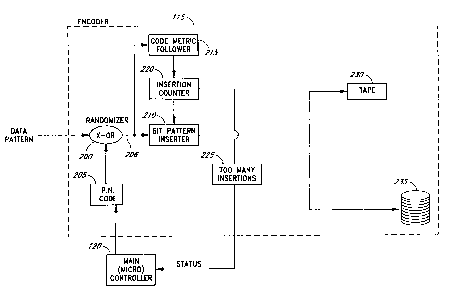
Figure 2 is a schematic block diagram that illustrates the main functional
elements of the
randomizer)bit-insertion encoder 115 of Figure 1a. As shown in Figure 2, a
data pattern input provided by the block
interleaver 110 enters a randomizer 200. In one preferred embodiment, the
randomizer 200 comprises an exclusive
OR gate.. which receives the input data pattern on a first input and receives
a pseudo~random noise code on a second
input via a second input from a pseudo-noise code generator 205. As will be
described in greater detail below, the
pseudo-noise code generator 205 comprises a shift register and adder
configuration, which is defined by a randomizer
polynomial, discussed in greater detail bekrw. Of course, it will be
appreciated that the randomization of data using
t
a linear feedback shift register (LFSR) is well understood and conventional.
By reinitializing the input values of the
pseudo-noise code generator register, the pseudo-noise code that is generated
by the generator 205 can be
reconfigured so that the pseudo-noise code can easily be changed on the fly
(e.g., in between data blocks).
The output of the randomizer 200 feeds to a bit pattern inserter 210, as well
as a code metric follower
215. The code metric follower 215 provides an input to an insertion counter
220, which in turn provides an input
to the bit pattern inserter 210. as well as to a bit-insertion threshold
detector 225. The bit-insertion threshold
detector 225 provides a status signal to the main microcontroller 120, which
in turn provides a control signal to the
pseudo-noise code generator 205.
The output of the bit pattern inserter 210 is provided to the data storage
media. As shown in Figure 2,
the media may comprise a magnetic tape 230 or a magnetic disk 235. It wiU be
appreciated by those of ordinary
skill in the art that the bit pattern inserter 210 is typically connected to
one or the other of the data storage media
230, 235, and is not typically connected to both simultaneously.
CA 02466569 2004-05-28
-6~
In operation, the data pattern from the interteaver 110 is exclusive ORed with
the pseudo~noise code to
produce an output data pattern on the fine 206 with an essentially random data
pattern dis~tribut'ron. As discussed
_ briefly above, data patterns that have an essentially random characteristic
(i.e., data distribution) are statisticagy ideal
for minimaing the number of data bits which must be inserted to break up
redundant patterns which increase the
ikelihood of a decoding error.
The randomized output over the line 206 is detected by the code metric
follower 215, which determines
whether or not the randomized data stream meets the three separate metric
criteria defined in accordance with the
present invention to mininize the likelihood of decoding error. The operation
of the code metric foNower 215 will
be described in greater detai below with reference to Figures 4-7.
1 D When the code metric follower 215 determines that a bit pattern is to be
inserted within the randomizer
data stream along the line 206, the insertion counter 220 is incremented, and
the appropriate bit pattern is inserted
by the b'rt pattern insertar 210. Although, in one preferred embodiment, the
bit pattern inserted comprises a four-bit
word, in practice, a single bit or. altemat'rvely, a multiple bit word (i.e.,
having two, three or more bits) could be
inserted as called for by the specific application. The method employed by the
bit pattern inserter 210 to insert the
appropriate bit pattern will be described in greater detail below with
reference to Figures 4 and 6. Once the bit
pattern is inserted, the data stream passes through a storage media for
permanent storage. For example, the data
stream may be written to the tape 230 or to the magnetic disc 235.
The insertan counter 220 keeps track of the number of bit patterns which are
inserted into the data stream
output by the b'rt pattern inserter 210. If too many insertions are detected
within the insertion detector 225, this
causes a signal to be transmitted to the micro controller 120. The micro
controller 120 controls the pseudo-noise
code generator 205 to reconfigure the pseudo-noise code output by the
generator 205. The method by which the
micro controller 120 modifies the pseudo-noise code output by the pseudo-noise
code generator 205 wiN be described
in greater defog below with reference to Figures 9 and 10.
Data written to either tape or disc can be encoded. As data is being written
to the magnetic disc 235,
if the disc sector size is exceeded due to variable rate encoding of the data
written to the sector, the block is
truncated at the end of the sector and the sector is overwritten with the same
data randomized using a different
randomizing code (i.e., saedl.
In this manner, not only can a data pattern be randomised to reduce the number
of b'rt insertions made on
a data stream to be stored, but the randomizer code can be reconfigured on the
ily so that, in the event that the
original randomizer code is insufficient to produce the number of bit
insertions under the tolerable amount, the
subsequent randomaing code will result in a bit insertion frequency which is
within the allowable limits for storage
on a magnetic medium.
Figure 3 is a schematic block diagram which illustrates the main functional
elements of the derandomaerlbit
extractor decoder 130 of Figure 1b. As shown kr figure 3, data storage media
such as the tape 230 or the disc
235 inputs data into an automatic gain control circuit 305 which automaticaly
adjusts the amplitude of the incoming
data stream to an appropriate level for monitoring by a code metric follower
310. Analog-to-digital conversion
CA 02466569 2004-05-28
.7.
hardware 307 is used to restore the analog signal output of the AGC circuit
305 to the digital bit stream written
to the magnetic media. The code metric follower 310 operates in substantially
the same manner as the code metric
follower 215 of Figure 2. The code metric follower 310 receives the data
stream output by the AID convertor circuit
307 and generates command signals to an extraction counter 315 as well as to
the main micro controller 120. The
input to the main micro controller 120 provides an indication to the micro
controller 120 that a particular b'rt pattern
detected within the data stream corresponds to an inserted bit pattern rather
than to the natural bit pattern of the
data. When the code metric follower in the decoder 310 detects a pattern that
contains an insertion, the extraction
counter 315 is notified. The extraction counter 315 removes the inserted data
bits and at the same time verifies
that the extracted bits are the correct polarity based upon the polarity of
the previous two decoded bits, as
described below with reference to Figure 8. If the polarity is incorrect, an
error status signal is generated to inform
the microcontroller 140.
The bit pattern extractor 320 outputs the data stream through a cyclical
redundancy code (CRC) check
circuit 325. The CRC check circuit 325 verifies that the appropriate bits are
extracted from the data stream and
outputs a signal to the micro controller 120 if an error has been detected.
When an error is detected by the CRC
check circuit 325, the block is flagged as an erasure. In the subsequent Reed-
Solomon decoder 145, the data,which
is tagged as an erasure is reconstructed using the correction capabilities
provided by the Reed-Solomon decoder 145.
As is well known in the art, Reed-Solomon encoding allows for error detection
as well as correction. The proportion
to the number of corrections to the number of defections can be varied
depending upon the desired application. In
the preferred embodiment of the invention, the Reed-Solomon encoderldecoder is
set to perform the maximum number
of corrections (i.e., to correct as many errors as are detected). This is
because the detection of errors is
advantageously performed using the CRC. In the event that more errors are
detected than can be corrected, the
microcontroller 140 requests a retransmission of the data. Once the data has
been checked by the CRC check circuit '
325, the data is once again exclusive ORed with the appropriate pseudo-noise
code via a derandomizer circuit 330
(comprising an exclusive-OR pate in one advantageous embodiment) and a pseudo-
noise code generator 335. The
pseudo-noise code generator 335 receives instructions from the micro
controller 120 indicating which pseudo-noise
code is to be used to decode a given block of data via the derandomizer 330.
As is well understood in the art, the
information concerning which code to use for derandomaation can be obtained
from the header portion of the block
of data, which is typically randomaed using a fixed code rather than a
variable code. Consequently, the same data
pattern which was initially written for storage to the tape 230 or disc 235 is
reproduced at the output of the
exclusive-OR gate 330, and transferred to the block de-interlesver 135 (see
Figure 1b) for further processbrg.
Figure 4 is a flowchart that illustrates the general method used in accordance
w'tth the present invention
to insert a data pattern in accordance with the variable-rate encoding method
of the present invention. As depicted
in Figure 4, the method initiates, as represented by a start block 400, and
enters four metric subroutine blocks 410,
420, 430, 435 for parallel processing to determine a null metric, a phase
metric, an automatic gain control IAGC)
metric, and a preamble pattern metric, respectively.
CA 02466569 2004-05-28
.8.
The null metric determined within the subroutine block 41 D, is used as a
measure of consecutive zeros
(commonly referred to as a null pattern) detected within the data stream. As
discussed briefly above, when a null
pattern persists within the data stream for an extended period, the effects
can be deleterious on the decoding sa
that errors are mare likely to occur. Thus, the subroutne block 410 tabulates
the length of a nud pattern and
outputs a flag or a metric value indicative of a nuH pattern. The method used
within the subroutine block 410 to
determine the null method is described in greater detail below with reference
Figure 5.
As represented within the subroutine block 420, the phase metric of the
incoming data stream is
determined. The phase metric is an indication of the phase content of the data
stream. As discussed briefly above,
it is important for a data stream to contain adequate phase content since data
decoding is based not only on
amplitude, but on phase. Thus, a decoder may lose calibration if the phase
content of the incoming data signal is
sufficiently low that the phase decoder is unable to sufficiently reca6brete.
This can result in inaccurate phase
measurements made by the phase decoder. Thus, as a measure of the phase
content of the incoming data stream,
the subroutine block 420 outputs a phase metric value. The method employed
whhin the subroutine bbck 42D is
descrbed in greater detail below with reference to Figure 7.
As represented within the subroutine block 430, the automatic gain control
(AGC) metric is determined.
For purposes of accurately determining the amplitude at which the read signal
shoukf be put to the A1D converter
307 (Figure 31, the automatic pain control circuit 305 must amplify the data
stream from the magnetic media to the
appropriate level. However, this AGC circuit 305 sometimes requires
recalibration. This recalibration depends upon
variations in the amplitude of a signal to determine the gain amplitude which
the signal ought to have. Thus, it is
particularly advantageous if the signal occasionally undergoes a maximum
amplitude variation while reading the data
pattern so that the AGC circuit 305 is able to recalibrate at the appropriate
intervals. Thus, if the determination
is made within the subroutine block 430 that a maxrcnum amplitude variation
has not occurred within a determined
interval, then an AGC flag. or a measurement value indicating how long it has
been since a maximum amplitude
variation, is output by the subroutine block 430. The method employed within
the subroutine block 430 to determine
the AGC metric is described in greater detail below with reference to Figure
6.
In one particularly advantageous embodiment of the invention, the code
follower 215 is configured to
monitor the header and data field portions of the data block in order to
ensure that the preamble pattern is not
reproduced outside of a preamble field. The monitoring for the preamble
pattern is performed within the subroutine
block 435. If 'rt is determined that any 14 b'rt portion of the preamble has
been reproduced elsewhere, then a flag
is set which causes the b'rt inserter to insert a single bit at the end of
this 14 bit sequence. In this case, the
inserted b'tt is chosen to be the same as the second to last encoded bit,
thereby ensuring that a preamble sequence
is not recorded in the header or data fields of a block.
The metrics determined within the subroutine blocks 410, 420. 430, 435 serve
as inputs to a decision block
440 which determines if any one of the nug, phase or AGC metrics has been
exceeded. In one advantageous
embodiment, the subroutine blocks 410, 420, 430, 435 simply set flags to
indicate that a metric threshold has been
exceeded. If any one of the metrics has been exceeded, then a bit pattern is
inserted into the data stream to
CA 02466569 2004-05-28
~9~
compensate for the "trouble spot," as represented within a subroutine block
450 (see Figure 81. However, if it is
determined within the decision block 440 that the metric has not been
exceeded, then the method returns to the
inputs of the subroutine blocks 410, 420, 430, 435. The appropriate metric
values are reset at the beginning of
each new block of data.
Figure 5 illustrates a flow chart of the submethod used to determine the null
metric within the null metric
subroutine block of Figure 4. The submethod begins as represented within a
start block 500, and a determination
is made 'rf the value stored within register R3 of the register=nnplemented
impulse response simulator of Figure 12
is equal to 0. As will be described in greater detail below with reference to
Figures 12 through 12d, the impulse
response of the read head used to read data from the magnetic storage media is
simulated as a means of estimating
the null, phase and AGC metrics. The value contained within the register R3 is
indicative of the duration of a null
pattern so that the value contained within the register R3 can be used to
determine whether or not a b'rt pattern
must be inserted to break up a null pattern.
If 'rt is determined that the value contained within the register R, is equal
to 0, as represented within the
decision block 505, then a counter (i.e., an R~ counter) is incremented, as
represented within an activity block 510.
However, if it is determined within the decision block 505 that the value
stored within the register R3 is not equal
to 0, then the R~ counter is cleared to 0, as represented within an activity
block 515, and the method returns to
the decision block 505.
Once the R3 counter has been incremented, a further test is performed, as
represented within a decision
block 520, to determine 'rf the value stored within the R, counter is equal to
10. If the value stored within the R3
counter is not yet equal to 10, then this indicates that the null pattern is
not sufficiently long to merit insertion of
a bit pattern. However, if it is determined that the value stored within the
R3 counter is equal to 10, then this is
an indication that the null pattern is of a sufficient length to require
insertion of a bit pattern to break up the null
pattern. Thus, 'rf the value stored within the R~ counter is less than 10, the
method returns to the decision block
505; however, if the value stored within the R, counter is equal to 10, then a
null metric flag is set to indicate that
a bit pattern is to be inserted by the bit pattern inserter 210, as
represented within an activity block 525. Once
the null metric flag has been set, as represented within the activity block
525 this indicates that an insertion will
be made. The R3 counter will then be automatically cleared to 0 when the
inserted bit pattern is detected since this
will cause R3 to set to a non-zero value. The method then returns to monitor
the value stored within the register
R~.
Figure 6 is a flow chart which illustrates a general method used in accordance
with the present invention
to determine the automatic gain control metric within the gain control metric
subroutine block of Figure 4. The
method begins, as represented within a start block 600, and a test is
performed to determine if the absolute value
stored within the register R~ is not equal to 2, as represented within a
decision block 605. As will be discussed
in greater detail below, the value stored within the register R3 may be used
as a measure of read amplitude. Thus,
if the absolute of the register R3 is not equal to 2, then this indicates that
the read amplitude has not exhibited a
maximum variation in the positive or negative directions. Thus, there is a
danger that the automatic gain control
CA 02466569 2004-05-28
1O~
will be unable to accurately calibrate, since a maximum amplitude variation
has not been observed by the automatic
pain control c'rccu'rtry. For this reason, the method of Figure 6 keeps track
of the number of clock cycles which
transpire between maximum amplitude variations. To accomplish this, an
automatic gain control counter is
incremented, as represented within an activity block 610. However, if it was
determined within the decision block
605 that the absolute value stored within the register R~ was equal to 2, then
this indicates that a maximum
amplitude variation has been observed by the AGC circuitry so that the AGC
counter is cleared to 0, as represented
within an aciiv'rty block 815. From the activity black 815, the method returns
to the decision block 605, where the
read amplitude is again monitored.
Once the AGC counter has been incremented, as represented within the activity
block 610, a determination
is made, as represented within a decision block 620, if the AGC counter has
incremented up to a value of 60. A
value of 60 stored within the AGC counter indicates that 60 clock cycles have
transpired since the last maximum
variation ~ amplitude, and it has been found that this number of clock cycles
is a convenient number at which to
insert an appropriate bit pattern for purposes of recalibrating the automatic
gain control circuitry. Thus, as depicted
in Figure 6, if the AGC counter increments to a value of 60, then an AGC
metric flag is set to indicate that the
appropriate bit pattern is to be inserted, as represented within an activity
block 825. If the AGC counter is not yet
incremented to a value of 60, then the method returns to the decision block
605 to continue monitoring read
amplitude variations via the value stored within the register R~.
As will be described in greater detail below with reference to Figure 8, in
order to determine which bit
pattern wig be inserted into the data stream, as indicated within the activity
block 625, the 2 bits within the data
stream prior to the inserted b'rt pattern are monitored, and a b'rt pattern is
selected in order to ensure that the
combination of the input bit pattern and the prior 2 data bits in the data
stream cooperate to produce a maximum
amplitude variation. Once the AGC null metric flag has been set, this will
cause the insertion of a bit pattern which
wiN subsequently clear the AGC counter to 0, as represented within the
activity block 615. In the meantime, the
method resumes monitoring the simulated read amplitude.
Figure 7 is a flow chart which llustrates the method used in accordance with
the present invention to
determine the phase metric w'tthin the phase metric subroutine block of Figure
4. The method initiates, as
represented within a start block 700, and the absolute value of the difference
between the value stored within the
register R5 and the R3 of Figure 12 is calculated, as represented within an
activity bbck 705.
Thereafter, the value cak:ulated within the activity block 705 is transformed
into a weighted average value,
as represented within an activity block 710. Since, in the embodiment
described herein, the value calculated within
the activity block 705 may be 0, 1, 2, 3 or 4, then the corresponding weighted
average values are 0, 2, 4, 6 and
6. For example, if the value calculated within the activity block 705 is 3,
then this value will be transformed to
a value of 6 within the activity block 710, while if the value calculated
within the activity block 705 is 4, then this
value will be transformed to a value of B within the activity block 710.
Thereafter, as represented by an acYrv'rty block 715, a moving average is
computed from the weighted
average values calculated for the all of the bits starting from the preamble
of the data block which have been
CA 02466569 2004-05-28
monitored for phase content. This moving average is recalculated each time a
new value is calculated within the
activity block 705. Advantageously, at the beginning of each data block, the
average value is set to some number
indicating near maximum phase content. As the moving average is calculated
this value varies as determined by the
actual phase content of the data stream. If this moving average falls beneath
a certain threshold value, then this
indicates that the data stream has a very low phase content, so that a bit
pattern should be inserted to improve
phase calibration. The reason for this is that the value stored within the
register R5 is a time delayed version of
the value stored within the register R3. Thus, the difference between the
values stored within the register R5 and
R3 is a measure of the rate of change of the data stream at a sample time
corresponding to the value stored w'tthin
the register R,. Thus, this differential value measures the phase content so
that from this differential value, an
indication can be made as to whether or not a bit pattern needs to be inserted
in order to increase the phase content
of the data stream.
Once the moving average has been calculated, a determination is made if this
moving average is less than
the threshold value, as represented within a decision block 720, in one
advantageous embodiment, the threshold
value is greater for the header field than for the data field isee Figure 11/,
however, the actual values used for these
threshold values may vary from application to application and may be
determined as called for by the particular
implementation. A phase metric flag is then set as represented within an
activity block 723, and the method returns
to monitor for phase content. In this manner, when a lack of phase content is
detected within the data stream, a
flag is set which causes a bit pattern to be inserted in order to increase the
phase content of the data stream.
However, if the moving average is above the threshold value, then the method
reenters the activity block 705 to
determine the next difference value.
Figure 8 is a flow chart which illustrates a submethod used within the insert
bit pattern subroutine block
of Figure 4 to select and insert the appropriate bit pattern into the input
data stream. The method initiates, as
represented by start block 800, and a determination is made if the preamble
pattern has been detected, as
represented within a decision block 801. If the preamble pattern has been
detected, then this causes the appropriate
bit to be inserted into the data stream, as represented within an activity
block 802. Otherwise, if the preamble
pattern has not been detected, a determination is made 'rf the flag which has
been set is the null metric flag, as
represented within a decision block 803. If the null metric flag has been set,
then a bit pattern of "1100" is
inserted into the data stream to breakup the null pattern, as represented
within an activity block 804. The insertion
of a data pattern of 1100 conveniently breaks up the null pattern, and also
includes phase and amplitude information
to provide for accurate phase and amplitude calibration. From the act'rv'rty
block 804, the method returns to the main
method of Figure 4.
If it is determined within the decision block 803 that the null metric flag
has not been set, then a
determination is made if the previous 2 bits in the data stream were "00," as
represented within a decision block
805. If the fast two bits were 00, then a bit pattern of 1100 is inserted into
the data stream, as represented
within an activity black 810, to produce a 6~bit pattern of "001100." However,
if it is determined within the
decision block 805 that the previous 2 data bits were not 00, then the method
proceeds to determine if the last
CA 02466569 2004-05-28
12-
2 bits were '01," es represented within a decision block 815. If the last 2
bits were 01, then a b'rt pattern of
1001 is inserted, as represented within an activity block 820, to produce a 6-
bit data pattern of "011001."
However, if the last 2 data bits is the data stream were not 01, then the
method proceeds to a decision black 825,
wherein a determination is made if the last 2 data bits were "10." If the fast
2 data bits in the data stream were
10, then a data pattern of 0710 is inserted, as represented within an activity
block 830, to produce a 6-b'rt data
pattern of "100110." However, if the last 2 data bits were not 10, then this
indicates that the last 2 data bits
were 11, so that a data bit pattern of 0011 is inserted into the data stream,
as represented within an activity block
840, to produce a 6-bit data pattern of "110011." It will be appreciated by
those skilled in the art that the method
of bit insertion descrbed above ensures that maximum phase and amplitude
information is inserted into the data
1D stream to assist the phase locked loop and the A6C circuit so that phase
lock and gain calibration are not lost.
Once the appropriate data bit pattern has been inserted within the activity
blocks 810, 820, 830 or 840,
then the method returns to the main method of Figure 4, as represented within
an activity black 850. In this
manner, the method of the preferred embodiment ensures that the appropriate
sufficient phase content wiU be
inserted into the data stream to provide far accurate phase lock calibration.
Furthermore, since the insertion of a
4.bit data pattern in accordance with the method of Figure 8 will result in a
maximum phase variation (i.e., R~ ~ RS
- 4 or .4), and since this value is weighted so that a maxwnum phase variation
wiU result in an even larger
contribution to the moving average, one bit pattern insertion should be
sufficient to raise the moving average well
over the threshold level so that the bit pattern insertion obtains optimum
phase content.
Figure 9 is a flow chart which illustrates the general method used in
accordance with the present invention
to reJ~onfigure the randomam polynomial when data is to be stored to a
magnetic disk. The method initiates es
represented within a start block 900 and thereafter, whenever a bit pattern is
inserted into the data stream, as
represented within an activity block 910, a determination is msde whether the
number of bits inserted is too large
for a given block of date es represented within a decision block 920. In one
embodiment, the number of insertions
is tabulated, and if four times this number of insertions is greater than the
nunber of bits which would cause the
data biiock to be too large for storage onto the disk, a flag is :et.
Thus, if it is determkred that the number of insertions has not exceeded the
threshold value, the method
returns to the activity black 910 for tabulation of the next bit pattern
insert. However, if it is determined that the
threshold value has been exceeded within the decision block 920, the method
proceeds to truncate the last data
block as represented within an activity block 930. That is, the data block
which is written to the disc is truncated
so as not to exceed the sector site to which the date block is written.
Thereatter, the randomizer initial settings
for the next data block to be randomized are changed by the microcontroUer
120, as represented within activity bbck
940. In one advantageous embodiment, the randomizer in'rtal settings can be
changed to settings for an orthogonal
pseudo-noise code to that which was used on the last block of data.
The method used to reconfigure a randomizing polynomial to produce an
orthogonal code is well known in
the art. Tha reconfiguration to an orthogonal code ensures that the next block
of data will not have a high
correlation with the new pseudo-noise code. This is because, orthogonal codes
have an essentially taro correlation
CA 02466569 2004-05-28
-13-
with one another so that, assuming that consecutive blocks of data have
essentially the same bit pattern
characteristic, when a bit pattern has a high correlation with a given pseudo-
noise code, the same pattern will have
a low correlation with a pseudo-noise code orthogonal to the original pseudo-
noise code. Thus, by changing the
randomizer initial settings for the next block of data so that the new pseudo-
noise code is orthogonal to the last
pseudo-noise code. the number of insertions for the data b-it stream can
always be reduced beneath the threshold
required for storage onto the disk.
In one preferred embodiment, the randomizing polynomial used to generate the
family of pseudo-noise codes
used to randomize the data stream is:
9rX~-~~+~~+~9+~B+~~+,r'6+~S+,r'~+,~3+Xro+~+X.+~+X+ ~
Finally, after the randomizer initial setting has been changed, the last block
of data, for which a number
of insertions was too high, is overwritten using the new pseudo-noise code as
represented w'tthin an activity block
950. All subsequent data blocks are also randomized using the new pseudo-noise
code. It should be noted that in
the case of the disk storage, it is possible to change the randomizer
polynomial coefficients on the fly and to
overwrite the last data block because of the characteristics of a disk storage
media which allow for overwrite an
the fly. Thus, in accordance with the method of Figure 9, data can be written
to a disk drive without the danger
that such data will be too large for storage purposes since changing of the
randomizer polynomial on the fly will
ensure that the percent increase for a given data block will never exceed the
sector space allocated for storage to
the magnetic disk.
It should be noted here, that in certain instances data has been encoded in
such a way as to anticipate
changes in a randomizer polynomial (i.e., with the specific intent of
producing a degenerate pattern) so that if a
straightforward method of changing the randomizer polynomial coefficient is
used, it is still possible that such data
streams will require an unacceptable number of bit insertions. Thus, in
accordance with a preferred embodiment,
the method of changing the randomaer polynomials is itself pseudo-random or
non-deterministic so that data streams
which are intentionally encoded to frustrate data storage in this method may
still be randomized in such a way so
as to reduce the number of b-'rt insertions to a tolerable level. As is well
known in the art, a number of mutually
orthogonal codes are associated within a family of codes defined by the
randomizer polynomial. Thus, any one of
the codes orthogonal to the code used last could be randomly chosen as the
next randomizer seed. Alternatively,
a complex, non-repetitive pattern for choosing consecutive codes could also be
used, as called for by the particular
application.
Figure 10 is a flow chart which illustrates the overall method used in
accordance with the present invention
to reconfigure the randomizer polynomial when the data storage media written
to is a magnetic tape. The method
initiates as represented within a start block 1000, and thereafter, any bit
insertions into the data stream are
tabulated as represented within an activity block 1010. If it is determined
that the number of insertions for a given
data block is within the allowable limits, as represented within a decision
block 1020, then the method returns to
the activity block 1010 to awa'tt the next insertion. However, ff 'tt is
determined within the decision block 1020
that the number of insertions has exceeded the allowable threshold level, then
a further determination is made within
CA 02466569 2004-05-28
.14.
a decision block 1030 if the number of insertions is too large for one or more
blocks of data. In one advantageous
embodiment, one block of data is monitored before 'rt is determined that the
number of insertions has been excessive
for too long of a time, however two, three or more blocks could also be
monitored es caled for by the particular
application. If a number of insertions has not been excessive for too long of
a period, then the method returns to
the activity block 1010. However, if it is determined within the decision
block 1030 that the number of insertions
has been too large for too long of a time, then the randomizer initial
settings fi.e., the coefficients to the randomizer
polynomial? are changed for the next block as represented within an activity
block 1040. The method employed
within the act'nity block 1040 is substantially identical to the method
employed within the activity black 940 of
Figure 9.
After the randomizer polynomial coefficients have been changed for the next
data block, the method returns
to the activity bbck 1010 to continue monitoring of the number of inserts into
the data stream. In this manner,
the preferred embodiment ensures that the number of brt insertions into data
to be stored onto a magnetic tape does
not increase the sue of the data to be stored above a tolerable limit (e.g., 1
%!.
Figure 11 schematically illustrates a format of a data block in one preferred
embodiment of the invention.
The overall block format is application specific. Each block preferably
consists of a series of framed sub-blocks
containing an interleaved series of systematic Reed-Solomon code words. Error
correction is based primarily on
erawres. This is efficient and uses a low bandwidth.
As shown in Figure 11, each data block includes a preamble, a header, a data
portion, a cyclical redundancy
check (CRC) portion and a postamble. The preamble typically comprises a
four.byte segment which is used to
identify the beginning of a new data bbck, end is advantageously not encoded
with the pseudo-noise code so that
it is not necessary to know the pseudo-noise cede in order to detect the
preamble segment. In one actual
embodiment, the preamble is "0100110011001100110D110011001111."
The header segment contains in'rtiafuation for the date segment scrambler, as
well as other information.
It is preferably a three byte sequence which is sent to the shared memory
resource by the microcontroUer 120 for
each 512. bytes data block received by the shared memory resource from the
host. The header field therefore
preferably consists of the first three bytes received by the encoder from the
direct memory access (DMAI channel.
Prior to recording, the header is randomaed using a fixed randomaer code
li.e., seedl. Because the header is
randomized using a fixed seed which is always available to the decoder 130,
the header randomizatan may result
in a header sequence with poor read characteristics. for instance, the fixed
header randomizer may produce a header
which contains a long string of zeros. Because re-randomaation is unavailable
for the header field, it is preferable
to use a different encoding scheme for the header field than the data field.
For example, the header could be
encoded using a fixed 4l5 or 819 code. This is less efficient than the
variable rate insertion code used on the data
block, but it provides a better assurance of reedability in the absence of re-
randomization. As a preferable
alternative, the variable rate bit insertion can be performed on the header,
but with different bit insertion thresholds
for null sequence length, phase content, and amplitude variations than are
utilized when writing the data field to
better ensure adequate read characteristics for the header f'~eld.
CA 02466569 2004-05-28
15-
The randomizer initialization is preferably identical for all sub~blocks in a
physical frame. Because of read
while write error correction, sub-blocks may be associated v~ith a track or
flame different from the physical track
or frame they are recorded in. Thus, information used to compensate for this
effect is included w'tthin the header.
The data field contains data which has been encoded using the randomizing
polynomial. This data field
includes the last 512 bytes from the AMA channel. In one advantageous
embodiment, randomization of the data
involves exclusive OR-ing the data with the least significant bit of the 24-
bit randomizing polynomial discussed above
according to a method which is well known in the art.
The CRC segment advantageously comprises a six byte field calculated from the
preceding header and data
fields after the randomization. This sub-block is never randomized and allows
a sub-block to be validated without
knowledge of the randomaer initialization. In one preferred embodiment, the
polynomial used to calculate the CRC
field is:
8~x~ °x'8+x'~'+x"+x'~+z'6+x"+~'+x"+x"+x'°+~b+xas+~s+~~+
~'+xi?+z~'+~°+xiv+x'-+x"+x~o+x9+xe+x'+xi+x+ J
The postamble field advantageously comprises a four-bit pattern such as 0101.
Figures 12-12d schematically illustrate the method used within a convolutional
encoder to simulate
the read head impulse response in order to determine the null, phase, and AGC
metrics. In order to
determine whether or not the read head used to read the data from the magnetic
media is receiving sufficient
amplitude and phase information, it is important to simulate the effects of
the read head using a partial
response simulation method. In the particular implementation used in the
preferred embodiment, the
extended partial response, class 4 (EPR4) is simulated since the simulation
using this method is closest to
the actual response observed in the read head used in the preferred
embodiment.
As depicted in Figure 12, a data stream is input into a parallel multiplier
circuit wherein each bit
of the data stream is simultaneously multiplied by either a positive one or a
negative one. As depicted in
Figure 12, a bit from the data stream is multiplied by a positive 1 and then
added to the value within a
register Ro, while the same bit is multiplied by 1 and added to the value
stored within a register element R,.
The same data bit is also multiplied by a -1 to be added to the value stored
within the register elements R2
and R" respectively. Upon each clock cycle, the value stored within the shift
register elements are shifted
over by 1 bit so that a convolutional encoding is performed to simulate the
read head impulse response.
For example, as depicted in Figure 12a-12d, assuming that the register
elements R°-Rs are initialized
to 0, when the first bit in the data stream is received, register elements
R°-R3 will respectively have values
of 1, 1, -1, -1, 0, and 0, as depicted in Figure 12a. Subsequently, the values
within the shift register
elements R°-RS are shifted by one element so that Rq is equal to 0, R,
is equal to 1, RZ is equal to 1, R, is
equal to -1, R, is equal to -1, and Rs is equal to 0.
Thereafter, when the next data bit in the data stream is applied, (e.g., a 0
as shown in Figure 12b),
this value is multiplied by the appropriate multiplier value and added to the
value stored within the shift
register elanents R°-Rs. Because the data stream value is 0 as shown in
the example of Figure 12b, this
does not change the value of any of the bits stored within the shift register
elements R°-Rs.
CA 02466569 2004-05-28
~16-
However, in the next clock rycle the data bits are shifted once again and the
next bit in the data
stream is then multiplied by the appropriate multiplier values and added to
the respective values within the
shift register elements Ra-R,. As depicted in Figure 12c, when a 1 is applied
in the next clock cycle, this
causes a value of 1 to be added to the 0 value stored within the shift
register element Ro, while a value of
1 is also added to the 0 value stored within the shift register element R,.
Furthermore, values of -1 are
added to the values stored within the shift register elements R~ and R,
thereby resulting in a net D value to
be stored within the shift register elements R, and R,. Finally, the shift
register elements R, and RS include
the shifted values of -1 and -l, respectively.
Once again, these values are shifted by one element (so that Ro-RS are now
equal to 0, l, l, 0, 0,
-1, respectively) and the next bit in the data stream is multiplied by the
appropriate factor and added to the
shift register elements Ro-R,. The subsequent multiplication and addition to
the value stored within the shift
register elements Ro-R, results in values of 1, 2, 0, -I, 0, and -1 to be
stored within the shift register
elements Ra-R" respectively.
As will be appreciated from the above-described method, whenever a long stream
of consecutive
zeros is input as the data stream, this will eventually cause the register
value of R, to assume a value of 0
for an extended number of clock cycles. Thus, the value stored within register
R, is indicative of a null
within the data stream. Furthermore, it will also be appreciated that the
value of R, is indicative of gain
content so that the value of R, will become a +2 or a -2 whenever a large
amplitude variation is observed
in the data stream. Thus, whenever a value of 2 or -2 has not appeared within
the register element R, for
an extended period of time, this indicates that the data stream is devoid of
amplitude information so that
a bit pattern which adds amplitude information must be inserted as described
above. Finally, it will be
appreciated that since the value stored within register element R, is simply a
time delayed version of the
value stored within register element R" the difference between the value
stored within the register elements
R, and RS taken during the same clock cycle will be indicative of the "slope"
of the impulse response
produced by the data stream at time R,. Thus, the difference between the value
stored within the register
element R, and the value stored within the register element R, is a measure of
the phase content, where a
large differeace indicates a high phase content and a small difference
indicates a low phase content.
Although the preferred embodiment has been described in detail above, it will
be appreciated by
one of ordinary skill in the art that certain obvious modifications could be
made to the preferred
3D embodiment without departing from the spirit or central characteristics of
the invention. For example, the
insertion counter could be implemented as a device which monitors overall
block size or the ratio of inserted
bits to non-inserted bits. Therefore the scope of the invention should be
interpreted in light of the following
appended claims.