Note: Descriptions are shown in the official language in which they were submitted.
CA 02466810 2004-05-18
WO 03/047385 PCT/US02/38700
TITLE OF THE INVENTION
[0001] Child-resistant Container
CROSS-REFERENCE TO RELATED APPLICATIONS
[0002] This application claims priority from U.S. Provisional Patent
Application No.
60/334,409, filed November 30, 2001 and entitled "child Resistant Container".
BACKGROUND OF THE INVENTION
[0003] The present invention relates to a child-resistant container and more
specifically to a
child-resistant container for storing a blister pack having an arrangement.of
blisters each of
which contains a tablet or capsule.
[0004] Many phamnaceutical products such as tablets and capsules are packaged
in blister
packs to deter children from obtaining and ingesting the products. The
designer of such blister
packs is confronted with conflicting requirements. The blister pack must be
child-resistant and
at the same time able to be opened without unreasonable difficulty. Typical
blister packs are
known to be difficult for some adults to open while still failing to be a
deterrent for
unsupervised children.
[0005] A child-resistant container for storing blister packs provides a second
layer of safety.
To be effective the container should require a degree of perception and manual
dexterity above
the abilities of unsupervised children attempting to gain access to the
contents of the blister
pack and should also be easy for adults to use. A container requiring the
coordinated use of
both hands and the simultaneous application of a force to both a latch and a
lock assembly to
gain access to the blister pack, such as the container of the invention
disclosed herein, should
provide the requisite level of protection.
SUMMARY OF THE INVENTION
[0006] In accordance with one aspect of the invention, a child-resistant
container for
holding at least one item includes a housing having upper and lower walls and
at least one open
side between the upper and lower walls and a tray that is pivotably connected
to the housing at
a pivot joint. The tray is adapted for holding at least one item and is
pivotable between a first
CA 02466810 2004-05-18
WO 03/047385 PCT/US02/38700
position in which the tray is in the housing for preventing access to the at
least one item and a
second position in which the tray extends through the at least one open side
of the housing for
exposing the at least one item. A latch comprising a flexible member is
connected to the tray.
The flexible member is biased into engagement with the housing when the tray
is in the first
position. A lock assembly is engageable with the tray when the tray is in the
first position. In
use, the tray is secured in the first position by the latch and the lock and
is angularly
displaceable from the first position to the second position upon the
simultaneous application of
a first force to the latch, a second force to the lock and a torque to the
tray.
BRIEF DESCRIPTION OF THE SEVERAL VIEWS OF THE DRAWINGS
[0007] The foregoing summary, as well as the following detailed description of
preferred
embodiments of the invention, will be better understood when read in
conjunction with the
appended drawings. For the purpose of illustrating the invention, there is
shown in the
drawings embodiments which are presently preferred. It should be understood,
however, that
the invention is not limited to the precise arrangements and instrumentalities
shown.
[000] In the drawings:
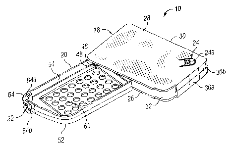
[0009] Fig. 1 is a top perspective view of a child-resistant container in
accordance with a
preferred embodiment of the present invention
[0010] F~. . 2 is a top perspective view of the child-resistant container in
Fig. 1 showing the
tray in the second (open) position;
(0011] Fig. 3 is a top plan view of the child-resistant container in Fig. 1;
[0012]~ Fig. 3a is a greatly enlarged view of a portion of Fig. 3 showing the
latch assembly;
[0013] Fig. 4 is a right side elevation view of the child-resistant container
in Fig. 3;
[0014] Fig. 5 is a front elevation view of the child-resistant container in
Fig. 3;
[0015] Fig. 6 is an exploded top perspective view of the child-resistant
container in Fig. l;
[0016] Fig. 7 is a top plan view of the child-resistant container in Fig. 1
showing a
preferred ornamental design for the top of the housing; and
[0017] Fig. 8 is a partial top plan view of the child-resistant container in
Fig. l, showing
another preferred ornamental design for the top of the housing.
2
CA 02466810 2004-05-18
WO 03/047385 PCT/US02/38700
DETAILED DESCRIPTION OF THE INVENTION
[0018] Certain terminology is used in the following description for
convenience only and is
not limiting. The words "right," "left," "lower" and "upper" designate
directions in the
drawings to which reference is made. The words "inwardly" and "outwardly"
refer to
directions toward and away from, respectively, the geometric center of the
child-resistant
container and designated parts thereof. The terminology includes the words
above specifically
mentioned, derivatives thereof, and words of similar import.
[0019] Referring to the drawings in detail, wherein like numerals indicate
like elements
throughout, there is shown in Figs. 1-7 a preferred embodiment of a child-
resistant container 10
in accordance with the present invention. The container 10 is for containing a
blister pack (not
shown) having an arrangement of blisters, each containing a tablet or capsule.
[0020] Those having ordinary skill in the art will appreciate from this
disclosure that
contents or items other than tablets or capsules can be contained in the
container 10 of the
present invention. For example, liquid or granular pharmaceuticals, contact
lenses suspended in
liquid or similar items potexitially hazardous to children or adults can be
safely contained in a
readily accessible and convenient manner using the container 10 of the present
invention.
Accordingly, while the preferred container 10 is discussed below as having a
tray 20 for
holding a blister pack, those having ordinary skill in the art will appreciate
from this disclosure
that the present invention is not limited to containers for containing blister
packs.
[0021] Thus, the container 10 can be used to contain other contents without
departing from
the scope of the present invention. The necessary changes to the container 10
to accommodate
contents other than a blister pack would be obvious to one of ordinary skill
in the aut when
considered in combination with this disclosure. Accordingly, for brevity; the
below disclosure
is directed to a container 10 for blister packs having an arrangement of
tablets with the
understanding that the invention is not limited to containing blister packs or
tablets.
[0022] Referring to Figs. 1-3 and 6, the container 10 includes a housing 18, a
tray 20, a
latch 22, and a lock assembly 24. The housing 18 has a generally rectangular
shape. However,
those of skill in the art will appreciate from this disclosure that the
container 10 of the present
invention is not limited to a container having a housing of any particular
shape. For example,
the housing 18 may be cylindrically shaped, triangularly shaped, cubically
shaped or the like
without departing from the scope of the present invention. Preferably, the
rectangular-shaped
housing 18 has first, second, third, and fourth corners 18a, 18b, 18c, 18d,
each of which has a
CA 02466810 2004-05-18
WO 03/047385 PCT/US02/38700
generally arcuate shape. The first corner 18a preferably has a radius of
curvature greater than
the second, third and fourth corners 18b, 18c,~18d and is adjacent to the
second and fourth
corners 18b, 18d. As will be discussed further below, those having ordinary
skill in the art will
understand that the first corner 18a having the greater radius of curvature
enables a user to
readily ascertain the orientation of the container 10. The artisan will also
understand that there
are numerous other methods that may be employed to enable the user to
determine the
orientation of the container 10, such as a faceted corner or the use of a
textured surface. Thus
the invention is not limited to the use of generally arcuate corners, one of
which having a
distinguishable difference in its radius of curvature over others, as the sole
method for
determining orientation.
(0023] Referring to Figs. 2-3 and 6, the housing 18 has a base 26, a top 28,
at least one
closed side 30 and at least one open side 32. The at least one closed side 30
extends between
the base 26 and the top 28 along a first portion 34 of a perimeter 36 of the
base 26. The at least
one open side 32 extends between the base 26 and the top 28 along a second
portion 38 of the
perimeter 36 of the base 26 and at least from the fourth corner 18d to the
first corner 18a.
Preferably the at least one closed side 30 comprises a base component 30a and
a top component
30b. The base component 30a extends upwardly from the base 26 and the top
component 30b
extends downwardly from the top 28. The top edge 40a of the base component 30a
of the at
least one closed side 30 has a rabbet 42a with an outwardly projecting lip
44a. The bottom
edge 40b of the top component 30b of the at least one closed side 30 has a
rabbet 42b with an
inwardly projecting lip (not shown) for mating in a snap fit connection with
the corresponding
rabbet 42a and lip 44a of the top edge 40a of the at least one closed side 30.
[0024] Those having ordinary skill in the art will understand from the present
disclosure
that the base component 30a and the top component 30b of the at least one
closed side 30 are
preferably formed as an integral part of the base 26 and top 28, respectively.
The artisan also
will understand that the base component 30a and the top component 30b may be
secured to
each other by a variety of other well known fastening methods such as an
interference fit,
screws, adhesives or the like. Further, the artisan will understand that the
base component 30a
and the top component 30b need not be formed as an integral part of the base
26 and top 28,
respectively, but rather may be separate structures secured to the base 26 and
top 28,
respectively, by the methods discussed above without departing from the spirit
and scope of the
invention.
4
CA 02466810 2004-05-18
WO 03/047385 PCT/US02/38700
[0025] A pivot 46 extends between the base 26 and the top 28 through the tray
20 as
discussed below. The pivot 46 is preferably positioned proximal to the fourth
corner 18d of the
housing 18 and comprises a first cylindrical structure 46a and a second
cylindrical structure
46b. The first cylindrical structure 46a is integral with the base and extends
upwardly from the
base 26. The second cylindrical structure 46b is integral with the top 28,
extends downwardly
from the top 28 and engages the first cylindrical structure 46a in peg-in-hole
like union. Those
skilled in the art will understand from this disclosure that the pivot 46 may
be any of a variety
of well known connectors that provide for angular displacement between to the
connected
structures, such as a hinge, without departing from the spirit and scope of
the invention.
[0026] The tray 20 preferably has a shape that generally corresponds to the
shape of the
base 26 and is preferably generally rectangular in shape. The tray 20 is
pivotably connected to
the housing 18. Preferably the tray 20 has a pivot hole 48 therethrough that
is joumaled with
the pivot 46. The tray 20 is pivotable between a first (or closed) position 50
(FIG. 1) in which
the tray 20 is in the housing 18 and a second (or open) position 52 (FIG. 2)
in which the tray 20
extends through the at least one open side 32 of the housing 18. The tray 20
has at least one
side 54 that extends upwardly along a first portion 56 of the perimeter 58 of
the tray 20 and that
corresponds to the at least one open side 32 of the housing 18. Those having
ordinary skill in
the art will understand from this disclosure that the at least one side 54
preferably, but not
necessarily, extends around the entire perimeter 58 of the tray 20. The tray
20 additionally has
a plurality of access holes 60 for providing access to the corresponding
arrangement of blisters
of the blister pack securable to the tray 20 by a plurality of pins 62
integral with the tray 20 and
extending upwardly therefrom.
[0027] Referring to Figs. 3, 3a and 6, the latch 22 comprises a flexible
member 64
associated with the tray 20 and a notch 66 associated with the housing 18. The
flexible member
64 has a first end 64a that is integral with the at least one side 54 of the
tray 20 and a second
end 64b that has an outwardly projecting tang 68. The flexible member 64 is
elastically biased
outwardly. The notch 66 is in an inwardly facing surface of the at least one
closed side 30 of
the housing 18. The notch 66 is proximal to the first corner 18a of the
housing and is
positioned for releasably engaging the tang 68 when the tray 20 is in the
first position 50 (FIG.
1). The outwardly facing surface of the latch 22 preferably, but not
necessarily, is a textured
surface. Those skilled in the art will understand from the present disclosure
that the latch 22
CA 02466810 2004-05-18
WO 03/047385 PCT/US02/38700
may be one of a variety of well known latching devices, such as a slider or a
snap without
departing from the spirit and scope of the invention.
[0028] Referring to Figs. 3 and 6, the lock assembly 24 is connected to the
housing 18 and
is engageable with a security aperture 70 in the tray 20 when the tray 20 is
in the first position
50 (FIG. 1). The lock assembly 24 preferably comprises a flexible upper tab
24a and a flexible
lower tab 24b. The upper tab 24a is preferably formed from a partial cutout in
the top 28 and
has a first end 72a integral with the top 28 of the housing 18 and a second
free end 72b. The
upper tab 24a is elastically biased outwardly and displaceable inwardly. The
lower tab 24b is
preferably formed from a partial cutout in the base 26 of the housing 18 and
has a first end 74a
integral with the base 26 and a second free end 74b. The lower tab 24b is
elastically biased
inwardly and displaceable outwardly. An upwardly extending push rod 76 is
integral with the
lower tab 24b proximal to the second free end 74b and engages the upper tab
24a. An upwardly
extending security boss 78 spaced from the push rod 76 is also integral with
the lower tab 24b
and is positioned for removable insertion into the security aperture 70 in the
tray 20, when the
tray 20 is in the first position 50. Those skilled in the art will understand
from the present
disclosure that other methods may be used to lock the tray 20 in the first
position 50 such an
outwardly biased bolt slideable within a bore in the top 28 of the housing 18
without departing
from the spirit and scope of the present invention.
[0029] Referring to Figs. 7-8, the upper tab 24a preferably has an ornamental
design such
as a star or a target applied to its outer surface as depicted in the
referenced figures to direct the
user's attention to the location of the upper tab 24a on the container 10.
Additionally,
preferably, but not necessarily, the top 28 of the container 10 may bear
markings such as the
markings shown in Figs. 7-8 providing guidance to the user regarding how to
operate the
device.
[0030] Those having ordinary skill in the art will understand from the above
disclosure that
the tray 20 is secured in the first position 50 by the latch 22 and the lock
assembly 24 and is
angularly displaceable from the first position 50 toward the second position
52 upon the
simultaneous application of an inwardly directed force to the flexible member
64 of the latch 22
and upper tab 24a of the lock assembly and a torque to the tray.
[0031] Preferably, but not necessarily, the above-disclosed components of the
container 10
are fabricated from die-formable polymeric materials. However, a wide variety
of well-known
6
CA 02466810 2004-05-18
WO 03/047385 PCT/US02/38700
materials including but not limited to metals such as aluminum or stainless
steel may be used
without departing from the scope and spirit of the invention.
[0032] The container 10 is preferably ergonomically designed for simplicity of
use as
follows. The container 10 with the tray 20 in the first or closed position 50
grasps the container
in the left hand with the at least one closed side 30 facing the palm of the
user's hand, the
top 28 facing upwardly and the left thumb placed over the upper tab 24a of the
lock assembly
24. The index finger of the user's right hand is placed on the flexible member
64 of the latch
22. To open the container 10, the user simultaneously applies with the left
thumb and right
index forger an inwardly directed force to the upper tab 24a and the flexible
member 64
respectively and a torque to the tray 20. The force applied to the upper tab
24a causes the upper
tab 24a to be displaced inwardly and thereby transfer the force to the push
rod 76 of the lower
tab 24b which, in turn, is displaced downwardly and outwardly to withdraw the
security boss
78 from the security aperture 70 and unlock the tray 20.
[0033] ~ The application of the inwardly directed force to the flexible member
64 causes an
inward displacement of the flexible member 64, which in turn causes the
withdrawal of the tang
68 from the notch 66 in the at least one closed side 30 of the housing 18. The
simultaneous
withdrawal of the security boss 78 and the tang 68 frees the tray 20 for
angular displacement
about the pivot 46. With both the upper tab 24a and the flexible member 64
inwardly
displaced, the application of the torque to the tray 20 pivots the tray 20
form the first (closed)
position 50 to the second (open) position 52.
[0034] When the tray 20 is in the open position 50, the user may either place
a new blister
pack in the tray 20 and secure it in position with the blister pack retention
pins 62, remove a
tablet from a blister of an already contained blister pack, or replace an
already present blister
pack with another.
[0035] The application of a reverse torque to the tray 20 returns the tray 20
to the closed
position 50. When the tray 20 is returned to the closed position 50, in the
absence of the force
applied to the upper tab 24a and the flexible member 64, the tang 68 is
inserted in the notch 66
and the security boss 78 is inserted in the security aperture 70 due to the
biased positioning of
the latch 22 and the lock assembly 24.
[0036] Those skilled in the art will appreciate that changes could be made to
the
embodiments described above without departing from the broad inventive concept
thereof. By
way of example, although the container 10 has been described for use with a
single blister pack
7
CA 02466810 2004-05-18
WO 03/047385 PCT/US02/38700
layer or the like, the container 10 may be arranged in a stacked configuration
to accommodate a
plurality of trays 20. It is understood, therefore, that this invention is not
limited to the
particular embodiments disclosed, but it is intended to cover modifications
within the spirit and
scope of the present invention as defined by the appended claims.
8