Note: Descriptions are shown in the official language in which they were submitted.
CA 02466924 2010-05-10
Real Time Interactive Video System
Cross-Reference to Related Applications
100011 This application is related to commonly-owned US patent No.
6,774,908, filed on
August 31, 2001 and issued on August 10, 2004 entitled "System and Method for
Tracking
an Object in a Video and Linking Information Thereto."
Computer Listing Appendix
[0002] This application includes a Computer Listing Appendix as provided on
pages 25
and 26 of this description.
Background of the Invention
1. Field of the Invention
10003] The present invention relates to a real time interactive video
system which
enables individual frames appearing in a sequence of video frames broadcast in
real time to
be selected
1
CA 02466924 2004-05-07
WO 03/041393
PCT/US02/36078
and stored for on demand access. Accessible within these frames are video or
pixel objects that
are linked to data objects on other resource platforms.
2. Description of the Prior Art
[0004] Various interactive video systems are known which allow viewer
interaction With
video content by way of various transport media, such as coaxial cable and
telephone wire. For
example, various N id lo on demand (VOD) systems are known which allow a user
to select video
content, such as movies, special event broadcasts and the like for playback.
Examples of such
video on (1.emand sistems are disclosed in U.S. Patent Nos. 5,752,160;
5,822,530; 6,184,878; and
6,204,843. In such video on demand systems, the user interface typically
includes a set top box
connected to transport media to provide a bi-directional communication link
between the user
and the video content provider. More specifically, video content selections
are transmitted to the
video content provider, such as a broadcast or cable TV provider. User content
selections are
processed by a so-called head-end processor, which processes the user's
request and causes the
selected video content to be transmitted to the user's set top box for
playback on a monitor or a
television.
[00051 Such video on demand systems are not real time systems. In
particular, the video
content in such video on demand systems is normally prerecorded and stored in
a suitable
storage media, such as a video content server, for transmission on demand. In
such video on
demand systems, the user controls the playback time of the selected video.
More specifically,
the playback time is determined by the time a request for the video content is
made by the user.
[0006] Other systems are known which provide interactivity with video
content on a real
time basis. Such systems are generally known as multicasting systems. Examples
of such
multicasting systems are disclosed in U.S. Patent Nos. 5,724,691; '5,778,187;
5,983,005 and
6,252,586. Such multicasting systems relate to video content distribution
systems which
simultaneously deliver multiple channels of video content in real time and
enable user to select
the content but not the time for receiving the selected video content.
[0007] = Systems which provide interactive messaging along with video content
are also
known. For example, U.S. Patent Nos. 5,874,985; 5,900,905 and 6,005,602
disclose video
messaging systems which overlay video content with programming or emergency
messages. In
such systems, the messages are continuously displayed until actively
acknowledged by an end
user.
2
CA 02466924 2004-05-07
WO 03/041393 PCT/US02/36078
[00081 Other interactive video systems are known which link static objects
in the video
content with other resource platforms. Examples of such systems are disclosed
in U.S. Patent
Nos. 5,781,228; 5,907,323; and 6,240,555. In particular, the '228 patent
discloses an interactive
video system in which static icons are displayed adjacent the video content.
The static icons are
linked to informational resources, such as audio, video or animated content.
[0009] U.S. Patent. No. 5,9J7323 discloses an interactive television
program guide. This
interactive system inciudes a display window adjacent the program guide which
can provide
additional information on selected programs when selected.
[0010] U.S. Patent No. 6,240,555 discloses an interactive video system
which provides static
links to other resource platforms. In particular, an interactive panel is
displayed adjacent the
playback window. The interactive panel includes various buttons including
educational and
merclandising buttons that are linked to other resource platforms. Selection
of one of the
buttons links the viewer to a collection of information related to the video
content. For example,
selection of the merchandising button displays a number of merchandising items
related to the
video content that are available for sale.
[0011] U.S. Patent Nos. 5,903,816; 5,929,850; and 6,275,989 disclose
interactive television
systems which include one or more broadcast channels and an on demand viewer
selection
channel. The on demand viewer selection channel includes static images related
to the video
content in the broadcast channels. The viewer may select one of the static
images for display or
link to other static images.
[0012] All of the systems described above relate to interactive video
systems which provide
interactivity with static pixel objects related to the video content. In order
to improve the
entertainment- level of such interactive video systems, systems have been
developed which
provide interactivity with dynamic pixel objects within the video content
itself. Examples of
such systems are disclosed in U.S. Patent Nos. 6,205,231 and 5,684,715. These
patents relate to
interactive television systems in which tags are embedded in the video
content. In particular,
tags are embedded for various pixel objects within the video content to enable
a pixel object to
be selected. Unfortunately, such systems are only suitable for on-demand
content. Such systems
have heretofore not been known to be suitable for real time broadcast.
[00131 Other systems have been developed to provide interactivity in
connection with real
time broadcasts. An example of such a system is disclosed in U.S. Patent No.
6,253,238. This
3
CA 02466924 2004-05-07
WO 03/041393
PCT/US02/36078
system provides interactive pseudo-web pages which can be selected to obtain
various types of
information, generally unrelated to the video content, such as e-mail
messages, sport scores,
weather and the like. Unfortunately, such systems do not provide interactivity
with the digital
content on a real time basis. Thus, there is need for an interactive video
system which provides
interactivity with the digital content on a real time basis.
=
Summary 3f the Invention
[0014] Briefly, the present invention relates to real time interactive
video system for use in
real time broadcasts as well as video on demand systems which requires no
modification of a
television set. In a real time broadcast application, the video content is
broadcast for playback on
a conventional television or monitor. Frames are extracted from the video
content in
predetermined time intervals, such as one second intervals, and stored in a
directory on an
Internet server. For example, for a 30 frame per second video source, one
frame of every 30 is
extracted and stored as a still image along with linked video files which link
pixel objects with
the stored frames to data objects, or other resource platforms. In order to
synchronize the stored
frames and linked video files with the real time video content broadcast, each
frame is either
numbered sequentially, or referenced by the time code of the frame from which
it was extracted.
Interactivity with the real time video content broadcast in real time is
provided by way of a
viewer interaction platform, for example, a computing platform, such as a
personal computer or a
set top box, or a wireless platform, such as personal digital assistant (PDA)
or cell phone, such as
a 3G cell phone, linked to the Internet server which hosts the stored frames
and linked video
files. In accordance with an important aspect of the invention, a video frame
interaction
application, resident on the view interaction platform, allows a viewer to
select specific frames
from the video content, as it is broadcast and stores these frames in the
memory of the viewer
interaction platform. If the viewer interaction platform has limited memory,
an Internet link to
the image can be saved. The frames are chosen by activating an "entry key" on
the view
interaction platform. The user selection is either sent to the website for
immediate retrieval of the
selected frame, or alternatively, the requested linked is saved for later
access to the website. The
website, upon request, sends the selected frame to the. video frame
interaction application which
allows the viewer to access pixel objects and link to other resource
platforms.
4
CA 02466924 2011-10-11
[0014a] According to an embodiment of the present disclosure there is provided
an image
processing system for processing video content in a sequence of video frames
and linking a
pixel object embedded in said video content to data corresponding to the pixel
object, the
image processing system comprising: a video capture system for capturing a
frame of said
sequence of video frames; a user interface for enabling a user to select the
pixel object in
said captured frame, said video capture system determining a range of color
values
corresponding to the selected pixel object; a pixel object tracking system
configured to track
the selected pixel object through a plurality of the sequence of video frames
based on the
determined range of color values; a video linking system which generates a
linked video file
that is separate from and not embedded in said sequence of video frames, said
linked video
file comprising (i) a pixel object file identifying the selected pixel object
by frame number
and location within the captured video frame and at least one subsequent video
frame, and
(ii) a separate data object file that includes information related to the
object that corresponds
to the selected pixel object, the data object file being linked to the
corresponding pixel object
file, wherein said linked video file is configured to be exportable to a media
player so that a
location in said sequence of video frames selected by a pointing device during
playback of
the video frames can be linked with the data object when said selected
location corresponds
to the selected pixel object; and wherein said video capture system determines
the range of
color values corresponding to the selected pixel object by: (i) determining a
value of at least
one of (ia) a hue, and (ib) a color variable, of at least one pixel of the
selected pixel object,
(ii) applying a predetermined value range to the determined value, (iii)
analyzing pixels that
(iiia) fall within a predetermined distance of said at least one pixel of the
selected pixel
object, and (iiib) fall within the applied value range, (iv) determining a
further range of
values based on the analyzed pixels, and (v) using the determined range of
further values as
said range of color values corresponding to the selected pixel object.
[0014b] According to another embodiment of the present disclosure there is
provided an
image processing system for processing video content in a sequence of video
frames and
linking a pixel object embedded in said video content to data corresponding to
the pixel
object, the image processing system comprising: a video capture system for
capturing a
sequence of video frames; a user interface for enabling a user to select a
pixel object in at
least one of the captured frames, said video capture system determining a
range of color
values corresponding to the selected pixel object; a pixel object tracking
system configured
to track the selected pixel object through a plurality of the sequence of
video frames based
4a
CA 02466924 2011-10-11
on the determined range of color values; and a video linking system which
generates a linked
video file that is separate from and not embedded in said sequence of video
frames, said
linked video file comprising (i) a pixel object file which identifies, by
frame number and
location within the frame, the selected pixel object in the captured frame and
at least one
subsequent frame, and (ii) a separate data object file which includes data
that corresponds to
the selected pixel object, said linked video file being configured to be
exportable to a media
player, wherein said video capture system determines the range of color values
corresponding to the selected pixel object by: (i) determining a value of at
least one of (ia) a
hue, and (ib) a color variable, of at least one pixel of the selected pixel
object, (ii) applying a
predetermined value range to the determined value, (iii) analyzing pixels that
(iiia) fall
within a predetermined distance of said at least one pixel of the selected
pixel object, and
(iiib) fall within the applied value range, (iv) determining a further range
of values based on
the analyzed pixels, and (v) using the determined range of further values as
said range of
color values corresponding to the selected pixel object.
100140 According to yet another embodiment of the present disclosure
there is
provided an image processing system for processing video content in a sequence
of video
frames and linking a pixel object embedded in said video content to
corresponding data, the
image processing system comprising: a video capture system for capturing a
sequence of
video frames; a user interface for enabling a user to select a pixel object in
at least one of the
captured frames, said video capture system determining a range of color values
corresponding to the selected pixel object; a pixel object tracking system
configured to track
the selected pixel object through a plurality of the sequence of video frames
based on the
determined range of color values; and a video linking system which generates a
linked video
file that is separate from and not embedded in said sequence of video frames,
said linked
video file comprising (i) a pixel object file which identifies, by frame
number and location
within the frame, the selected pixel object in the at least one captured frame
and at least one
subsequent frame, and (ii) a separate data object file, linked to the pixel
object file, which
includes data corresponding to the selected pixel object, said video linking
system being
configured to be exportable to a media player, said video linking system
clustering the
sampled video content with plural frames per cluster, wherein said video
capture system
determines the range of color values corresponding to the selected pixel
object by: (i)
determining a value of at least one of (ia) a hue, and (ib) a color variable,
of at least one pixel
of the selected pixel object, (ii) applying a predetermined value range to the
determined
4b
CA 02466924 2011-10-11
value, (iii) analyzing pixels that (iiia) fall within a predetermined distance
of said at least one
pixel of the selected pixel object, and (iiib) fall within the applied value
range, (iv)
determining a further range of values based on the analyzed pixels, and
(v)using the
determined range of further values as said range of color values corresponding
to the selected
pixel object.
4c
CA 02466924 2004-05-07
WO 03/041393 PCT/US02/36078
Description of the Drawings
[0015] These and other advantages of the present invention will be readily
understood with
reference to the following specification and attached drawing wherein:
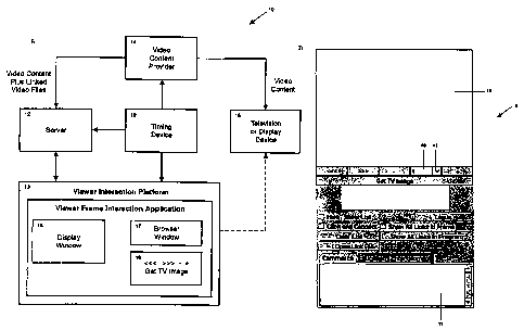
[0016] FIG. 1 A is a block diagram of the real time interactive video
system in accordance
with the present invention.
[0017] FIG. 1B is an exemplary graphical user interface for use with the
real time interactive
video system illustrated in FIG. 1A.
[0018] FIG. 2 is a software flow diagram of the frame capture and export
application in
accordance with the present invention.
[0019] FIG. 3 is a block diagram of an exemplary frame buffer for use with
the present
invention.
[0020] FIGS. 4A and 4B are software flow diagrams of the navigational
control buttons for
use with the present invention.
[0021] FIG. 5 is a block diagram of a system for generating linked video
files for use with
the present invention.
[0022] FIG. 6 is a screen shot of a developmental graphical user interface
for use in a
developing the linked video files.
[0023] FIG. 7 is a system level software diagram of the system illustrated
in FIG. 5.
[0024] FIG. 8 is a software flow diagram of the system illustrated in FIG.
5, illustrating a
frame extraction application.
[0025] FIGS. 9A and 9B are flow diagrams of the pixel object capture
portion of the system
illustrated in FIG. 5.
[0026] FIG. 10 is a flow diagram of the automatic tracking portion of the
system illustrated
in FIG. 3.
[0027] FIG. 11 illustrates the automatic tracking of an exemplary red
frame against a
blue background for two successive frames for the system illustrated in FIG.
10.
Detailed Description
[0028] The present invention relates to a real time interactive video
system for use with both
real time and video on demand content. In accordance with an important aspect
of the invention,
the video content is preprocessed, for example, by a video content provider,
or application
CA 02466924 2010-05-10
service provider, by a method which creates linked data files that identify
interactive pixel
objects within the content by frame number and the x, y coordinates of each
object. The
creation of the linked video files is described in detail in connection with
FIGS. 5-11. In
general, the linked data files also include data object files which link the
various pixel
objects to a uniform resource locator, fixed overlay information, a streaming
video link, a
database interaction link or other resource platform hereinafter "data
object". As will be
discussed in more detail below, the use of linked data files avoids the need
to embed tags in
the original video content. However, the principles of the present invention
are also
applicable to video content with embedded tags, embedded either by manual or
automatic
authoring image processing systems, such as disclosed, for example, in U.S.
Patent No.
6,205,231.
Video Content File Storage
[0029] In addition to preprocessing of the video content as discussed
above, the video
content is partitioned into predetermined time segments, for example, one
second segments,
hereinafter "frames". These frames are converted to a small image file type,
such as a .jpeg,
.tif or .gif file. Each of the image files, which represent a frame, is
sequentially numbered
and stored in a directory hosted by a server 12 (FIG. 1), such as a web
server. In particular,
the first frame of video content is identified as one; the second one second
section as two,
etc. As will be discussed in more detail below, such a file structure for
storage of the video
content facilitates synchronization of the real time broadcast with playback
of the video
content on a video playback platform 13 to provide interactivity with the
video content on a
real time basis.
[0030] Alternately the images which represent the video content frames may
be
identified by the time code number taken from the video frame from which it
was created,
and stored in a directory hosted by a server. In this method synchronization
between
broadcast programming and the linked data files is provided by analysis of the
time code
numbers.
[00311 In accordance with an important aspect of the invention, broadcast
of the video
content by the video content provider is synchronized or near synchronized
with the digital
content exported from the server 12 to the video playback platform 13 by way
of a timing
device 19. As will be discussed in more detail below, such timing devices are
normally used
to generate timing signals that are transmitted by video content providers and
distributors 14
6
CA 02466924 2010-05-10
to synchronize all of the broadcasts of the video content throughout the
broadcast network.
Leitch Technology Corporation is known to provide such timing signals for many
known
video content providers and distributors 14. An example of such a timing
device, identified
with the reference numeral 19, as provided by Leitch Technology Corporation,
is disclosed
in U.S. Patent No. 6,191,821. Such a system is known to be accurate to one
second per year.
[0032] Alternately, the synchronization between the video images being
broadcast and
the images files being in a directory on a server may be maintained by a
computer device
created to accurately read time code information from an on-going broadcast
and trigger
computer commands based on information programmed into its memory based on the
time
code information of the program being broadcast. Mixed Signals, Inc.
(http:/www.
mixedsignals.com) is known to provide such monitoring technology.
[00331 In accordance with the present invention, the timing signals from
the timing
device 19 are also applied to the server 12 as well as to the viewer
interaction platform 13.
As such, the broadcast of the video content by the video content provider or
distributor
allows for interactivity with the digital content on a real time basis, as
will be discussed in
more detail below. Alternately, if a time code is being used as the method to
provide
synchronization, the timing device 19 sends a frame accurate time code signal
to the server
12 hosting the content information. Thus, when a request is sent by the video
frame
interaction application to the server 12, the server 12 synchronizes the
request to the
incoming information regarding the frame being broadcast at that moment and
sends the
appropriate frame image.
Video Frame Interaction Application
[00341 As shown in FIG. 1A, a view interaction platform 13 is provided to
enable a
viewer to interact with video content on a real time basis with absolutely no
modifications to
the television or display device. The viewer interaction platform 13 may be a
computing
platform, such as a personal computer or a set top box, or a wireless
platform, such as
personal digital assistant (PDA) or a cell phone, such as 3G cell phone or
other wireless
devices. A viewer frame interaction application, resident on the viewer
interaction platform,
may be used to support a display window 16, a browser window 17 implemented,
for
example, as a graphical user interface, for example, as shown in FIG. 1B and a
set of control
buttons, collectively identified with the reference numeral 18, and displayed.
In
embodiments in which viewer interaction
7
CA 02466924 2004-05-07
WO 03/041393 PCT/US02/36078
platform 13 does not include a display, such as a set top box embodiment, the
display window 16
and browser window 17 and control buttons may be displayed on the television
or display 15, for
example, after the broadcast of the video content.
[0035] The images shown in the display window 16 are controlled by the
control buttons 18.
The display window 16 is for displaying the selected video frames while the
browser window 17
may be used to display the information that resides in the linked video files,
such Is the data
objects.
Interactive Real Time Video Playback
[0036] The frames of the video content are stored in a directory on the
server 12 and
synchronized in one of two ways with a broadcast program in order to provide
interactivity with
the video content on a real time basis. For example, frames are extracted from
the video content
in predetermined time intervals, such as one second intervals, and
sequentially stored in a
directory on the server 12. In the first embodiment, where synchronization is
based on time, the
system monitors the control buttons 18 (FIG. 1). Any time a "Get TV Image"
control button 18
is selected, or button with a similar function, as indicated in step 21 (FIG.
2), the request is time
stamped in step 23. The time stamp request is exported via the Internet to the
server 12 which
locates the frame file corresponding to the time stamp in step 25. In
particular, a user request,
for example at 8:08:05 p.m. would correspond to file number 485 (60 sec/min x
8 min x 1
file/sec +5 sec x 1 file/sec) since, in this example, the video content is
stored in the server 12 in
one second segments. The frame file is exported to the video frame interaction
application 13 in
step 27
[0037] In the second embodiment, where a time code is used as a
synchronization method, a
computer, for example, located at the broadcast facility, monitors a video
program as it airs. As
the program airs, the time code information is sent to the server 12. When the
"Get TV Image" or
similar button is activated, a request for the frame being broadcast at that
moment is immediately
sent to the server 12. The server 12 synchronizes the request with the frame
information being
sent from the computer monitoring the broadcast. The server 12 processes the
request and sends
the video frame interaction application the frame closest in time to the one
requested, since the
frames are stored in one second intervals.
8
CA 02466924 2004-05-07
WO 03/041393 PCT/US02/36078
[0038] As shown in FIG. 3, all of the frames that correspond to time stamps
or time codes
may be stored in a frame buffer 29 located at the server 12 in sequential
order along with the
linked video files which link data objects with specific pixel objects in each
of the frames.
During the program, or at the end of the broadcast, the viewer then has the
option of reviewing
the frames in the frame buffer 29 for pixel objects of interest in those
frames as discussed below.
[0039] In order to facilitate navigation of the frames, various frame
navigational buttons are
provided. For example, local frame advance navigation buttons may be provided.
In particular,
a <<< (back) button allows a viewer to page back through frames locally stored
in the viewer
interaction platform 13 on frame by frame basis. Server frame advance buttons
may also be
provided. These server frame advance buttons allow a user to page through
unselected frames on
the server 12 (FIG. 1). In particular, a (+) button allows a user to page
forward through
unselected frames in the server 12 on a frame by frame basis. A (-) button
allows a user to page
backward through unselected frames in the server 12 on a frame by frame basis.
[0040] FIGS. 4A and 4B are flow charts for the navigational buttons. With
reference first to
FIG. 4A, the system monitors in step 31 whether any of the navigational
buttons are depressed.
If not, the system continues to monitor whether any of the navigational
buttons are depressed. If
one of the navigational buttons is depressed, the system checks in steps 33-39
(FIGS. 4A and 4B)
to determine which navigational button was depressed or whether data has been
entered into a
frame advance dialog box 40 (FIG. 1B) in step 41.
[0041] If the system determines in steps 33 or 35 that one of the local
frame advance
navigational buttons, <<<or >>>, has been selected, the system pages either
backward or
forward, depending on the local frame advance navigational button selected,
through frames
locally stored in the viewer interaction platform 13 (FIG. 1) on a frame by
frame basis and
displays the selected frame in the display window 16 in steps 49 or 51,
respectively. Similarly, if
the system determines in steps 37 or 39 (FIG. 4B) that one of the server frame
advance control
buttons, (+) or (-), have been selected the system, in steps 53 or 55, pages
either backward or
forward, depending on the server frame advance navigational button selected,
through unselected
frames stored at the server 12 (FIG. 1) and displays the selected frame in the
display window 16.
[0042] If the system determines that none of the frame advance navigational
buttons have
been selected, the system checks in step 41 (FIG. 4B) whether a data value has
been entered into
the frame advance dialog box 40 (FIG. 1B). The frame advance dialog box 40
allows unselected
9
CA 02466924 2004-05-07
WO 03/041393 PCT/US02/36078
frames stored at the server 12 (FIG. 1A) to be called on a time interval
basis. A drop down menu
43 (FIG. 1B) may be provided to provide a choice of time intervals, for
example, seconds or
minutes. After the system determines that a data value has been entered into
the frame advance
dialog box 40 (FIG. 1B), the system determines the previously selected time
interval, for
example, seconds or minutes, to determine the selected frame. For example, if
the number 2 has
been entered in the frame advance dialog box 40 and the "minutes" time
interval was previously
selected by way of the drop down menu 43, the system would call, for example,
file number 120
(60 sec/min x 2 minutes x 1 file/sec) in step 59 and display the selected
frame in the display
window 16 (FIG. 1).
Interaction Video Graphical User Interface
[0043] Playback of the video content and linked video files 24 is by way of
the viewer
interaction platform 13 (FIG. 1). The viewer interaction platform 13 includes
the viewer frame
interaction application which supports a common media player API 40 for
playback of the video
content and provides resources for accessing the linked video files to enable
pixel objects to be
selected with a standard pointing device, such as a mouse, and linked to one
or more data
objects.
[0044] In particular, the viewer frame interaction application reads the
linked data files
discussed above and stores these files in two arrays. The first array may be
single dimensional
and may contain information about the video content and in particular the
segments. The second
array may be used to provide information regarding the location of the pixel
objects of clickable
areas for each movie segments. Exemplary code for storing the linked data
files into a first array
and a second array is provided in an Appendix.
[0045] The video frame interaction application enables pixel objects within
the video content
to be selected with a standard pointing device, such as a mouse. The (x, y)
coordinates of the
location selected by the pointing device for the selected frame number is
captured and compared
with information in the linked video files 24 to determine whether the
selected location
corresponds to a selected pixel object. In particular, the (x, y) coordinates
and frame number are
compared to a pixel object file (discussed below) to determine if the selected
location in the
display window 16 corresponds to a pixel object. More specifically, for the
selected frame, all
clickable areas in the frame are scanned to determine the clickable area or
pixel object that
CA 02466924 2004-05-07
WO 03/041393 PCT/US02/36078
contains the x, y coordinates associated with the mouse click. If so, the
system displays the data
object that has been linked to the pixel object by way of the link index in
the object file in the
browser window 17 to provide user interaction with the video content broadcast
in real time or
on demand. Exemplary code for returning a link index is provided in the
Appendix.
[0046] The video frame interaction application 42 may also provide for
additional capability.
For example, the graphical user interface 20 may be provided with buttons for
categorizing the
various data objects that have been linked to the video content. As shown, in
FIG. 1B, the
graphical user interface 9 may include categorical buttons, such as the
entertainment, commerce
and education buttons to display the data objects in each of the exemplary
categories. These
category titles may be customized for each program, and are dynamically
written to reflect the
content of the program being shown. In this configuration, the data object
files are configured
with such categorical information. As such, when one of the categorical
buttons is selected, all
of the selected links in that category are retrieved from the linked video
files and displayed in
browser window 17.
[0047] The graphical user interface 9 may also include additional
functionality, for example,
as seen in FIG. 1B. In particular,"Show All Links in a Frame" and "Show All
Links in Program"
buttons may also be provided. The "Show All Links in Frame" button displays
all links in a
given frame in the display window when selected. This function allows a user
to scroll through
the access content, for example, by way of a scroll buttons to locate the
scene or frame in which
the desired item appears. Once the frame has been located, the user can click
within the
displayed frame and all of the available items contained within the display
frame are sorted and
displayed in the display window. The "Show All Links" button, when selected,
displays all of
the data object links to the Video content. The` data objects are displayed-in-
the display 'Window.
[0048] "Hide/Show List", "Login", "Clear List" and "Open Link" buttons may
also be
provided. The "Hide/Show List" button may be used to hide or show the
functions of the
graphical user interface 9. In particular, when the "Hide/Show List" button is
selected, an on/off
state is toggled and stored in memory.
[0049] The Login button may be used to prevent or limit access by the video
from interaction
platform. The login capability may be used to capture valuable data about the
user's habit and
requested information. In this application, a web server (not shown) may be
used to host a
database of user information and password information commonly known in the
industry. When
11
CA 02466924 2004-05-07
WO 03/041393 PCT/US02/36078
the Login button is selected, a request is sent from the viewer interaction
platform 13 to a login
web server for authentication. An authentication message is then returned to
the viewer
interaction platform 13 to enable playback of the linked video content.
[0050] The Clear List button may be provided to delete all of the data
objects in the display
window 16. When the Clear List button is selected, the viewer interaction
platform deletes 13
all of the data objects in a temporary memory used for the display window 16.
An Open Link
button allows for additional information for selected data objects to be
accessed. In particular,
once a data object is selected from the display window, selection of the open
link button may be
used to provide any additional information available for the selected data
object.
Video Content Pre-Processing
[0051] As mentioned above, the system in accordance with the present
invention is suitable
for use for both real time broadcast and video on demand video content. The
video content is
pre-processed as discussed below to create the linked video files as discussed
above. The pre-
processing discussed below is merely exemplary. Other types of pre-processing
may also be
suitable.
[0052] In an exemplary embodiment in a development mode of operation, the
video content
may be preprocessed by an image processing system for automatically tracking a
pixel object,
selected in a frame of a video frame sequence, in preceding and succeeding
video frames for the
purpose of linking the selected object to one or more data objects. The image
processing system
compensates for changes in brightness and shifts in hue on a frame by frame
basis due to lighting
effects and decompression effects by determining range limits for various
color variable values,
such as hue (H), red ¨ green (R ¨ G), green ¨ blue (G ¨ B) and saturation
value2 (SV2) to provide
relatively accurate tracking of a pixel object. Moreover, unlike some known
image processing
systems, the exemplary image processing system does not embed tags in the
video content.
Rather the exemplary system, generates linked video files, which identify the
pixel coordinates
of the selected pixel object in each video frame as well as data object links
associated with each
pixel object. The linked video files are exported to the viewer interaction
platform 13 which
includes the viewer frame interaction application which supports playback of
content of various
compression schemes such as those used by various commonly known media
players, such as
Real Player, Windows Media Player and Quick Time and enables pixel objects to
be selected
12
CA 02466924 2004-05-07
WO 03/041393 PCT/US02/36078
during playback with a pointing device, such as a mouse which enables access
to linked to data
objects.
[0053] A graphical user interface (GUI) may be provided to facilitate the
development of
linked video files during a development mode of operation. In particular, a
developmental GUI,
for example, as illustrated in FIG. 6, may be used to facilitate processing of
the original video
cont Ir by either a video content provider or an application service provider,
to develop the
linkc 1 iideo files as discussed above.
[0054] Various embodiments of the exemplary video content pre-processing
are
contemplated. For example, referring to FIG. 5, the system may be implemented
by way of a
resource platform, shown within the dashed box 20, formed from one or more
servers or work
stations, which may constitute an Application Service Provider or may be part
of the video
content producer. In this implementation, a source of video content 22, for
example, an on-
demand source from, for example, a DVD player or streaming video source from a
video content
producer, is transferred to the resource platform 20, which, in turn,
processes the video content
22 and links selected pixel objects within the video content 22 to data
objects and generates
linked video files 24.
[0055] The resource platform 20 is used to support a development mode of
operation in
which the linked video files 24 are created from the original video content
22. As shown in FIG.
5, the resource platform 20 may include an exemplary resource computing
platform 26 and a
video processing support computing platform 28. The resource computing
platform 26 includes
a pixel object capture application 30, a video linking application 32 and
generates" the linked
video files 24 as discussed above. The pixel object capture application 30 is
used to capture a
pixel object selected in a frame of video content 22. The video linking
application 32
automatically tracks the selected pixel object in preceding and successive
frames in the video
sequence and links the pixel objects to data objects by way of a pixel object
file and data object
file, collectively referred to as linked video files 24. The linked video
files 24 are created
separately from the original video content 22 and are amenable to being
exported to the server 12
(FIGS. 1 and 5).
[0056] The resource computing platform 22 may be configured as a work
station with dual
1.5 GHz processors, 512 megabits of DRAM, a 60 gigabit hard drive, a DVD-RAM
drive, a
display, for example, a 21-inch display; a 100 megabit Ethernet card, a
hardware device for
13
CA 02466924 2004-05-07
WO 03/041393
PCT/US02/36078
encoding video and various standard input devices, such as a tablet, mouse and
keyboard. The
resource computing platform 26 is, preferably provided with third party
software to the
hardware.
[0057] The video processing support computing platform 28 includes a show
information
database 34 and a product placement database 36. The show information database
34 includes
identifying inform ati m relative to the video content, such as show name,
episode number and the
like. The product placement database 36 includes data relative to the various
data objects, such
as website addresszs, to be linked to the selected pixel objects. The show
information database
34 as well as the product placement database 36 may be hosted on the video
processing support
computing platform 28 or may be part of the resource computing platform 26.
Development Mode of Operation
[0058] The development mode of operation is discussed with reference to
FIGS. 7-11.
Turning to FIG. 7, a video source, such as, a streaming video source, for
example, from the
Internet or an on-demand video source, such as a DVD player, is imported by
the pixel object
capture application 30 (FIG. 5) which captures, for example, 12 frames per
second of the video
content 20 and converts it to a bit map file 44. In particular, the video
content 22, for example,
in MPEG format, is decompressed using public domain decoder software,
available from the
MPEG website (www.mpeg.org) developed by the MPEG software simulation group,
for
example, MPEG 2 DEC, an executable MPEG 2 decoder application. As is known in
the art,
such MPEG decoder software decodes an entire MPEG file before providing global
information
on the file itself. Since the video content must be identified by frame for
use by the pixel object
capture application 30 and the video linking application 32, the frame
information may be read
from the decoded MPEG file once all of the frames have been decoded or
alternatively
determined by a frame extraction application which stores the frame
information in a memory
buffer as the MPEG file is being loaded into the pixel capture application 30
as illustrated in
FIG. 8 and described below.
Frame Extraction Application
[0059] The frame extraction application is illustrated in Fig. 8 and
described below.
Referring to FIG. 8, the MPEG file is imported into the pixel object capture
application 30 in
14
CA 02466924 2004-05-07
WO 03/041393 PCT/US02/36078
compressed format in step 46. In this embodiment, the pixel object capture
application 30 works
in conjunction with the standard MPEG decoder software as illustrated in FIG.
8 to avoid waiting
until the entire file is decoded before obtaining the frame information. While
the MPEG file is
being imported, the pixel object capture application 30 reads the header files
of the MPEG data
in step 48 and stores data relating to the individual frame type and location
in a memory buffer in
step 50. As such, the pixel object capture system 30 is able to decode
selected frames of the
compressed MPEG file without the need for decoding all of the previous frames
in step 52.
Based upon the frame information stored in the memory buffer in step 50, the
decoded MPEG
files may then be converted to a bit map file 44 (FIG. 7), as discussed above
in step 54.
Section Break Application
[0060] The pixel object capture application 30 may optionally be provided
with a section
break application 55 (FIG. 7) to facilitate downstream processing and aid
partitioning of the
content among several users. The section break application 55 analyzes the
video content during
loading. The section break data is stored in a temporary buffer 56 (FIG. 7)
and used for pixel
object analysis of a selected frame and proceeding and succeeding frames by
the pixel object
capture application 30 and the video linking application 32.
[00611 The section break application 55 automatically analyzes the video
content to
determine how changes in lighting affect RGB values creating large shifts in
these values. In
particular, the median average of the pixel values for a series of frames is
computed. The
section break application 55 compares the changes in the pixel values with the
median average.
A section break may be determined to be an approximately 5x change in pixel
values from the
median average. These section breaks are stored in a buffer 56 as a series of
sequential frame
numbers representing (start frame, end frame) where each start frame equals
the proceeding
frame plus one frame until the end of the video. This information may be
edited by way of the
graphical user interface 60 (FIG. 6), discussed below. If changes are made to
the frame numbers
corresponding to the section breaks, the new information is sent to the
section break memory
buffer 56 (FIG. 7) where the original information is replaced.
[0062] As will be discussed in more detail below, the frames in the video
content are
analyzed for a selected pixel object during a session with the pixel object
capture application 30
(FIG. 5). A pixel object may be selected in any frame of a video sequence 57
(FIG. 7). The
CA 02466924 2010-05-10
video linking application 32 processes preceding and subsequent frames 59 by
automatically
tracking the selected pixel object and generating linked video files 24 for an
entire segment
as defined by the segment break application, or for a length of frames
determined by the
operator. The segment may be as small as a single frame or may include all the
frames in the
content.
Developmental Graphical User Interface
[0063] In order to facilitate development, a developmental graphical user
interface 60
may be provided, as illustrated in FIG. 6. As shown, the developmental
graphical user
interface 60 includes a viewing window 61 for displaying a frame of video
content and a
number of exemplary data fields to associate information with the video
content.
[0064] An exemplary product placement list display window 62 is used to
provide a
graphic list of all of the data objects associated with a particular video
frame sequence. The
product placement list display window 62 is populated by the product placement
database 36
(FIG. 5). The list of data objects is propagated anytime the developmental
graphical user
interface 60 is created or an existing graphical user interface 60 is opened.
[0065] As shown in FIG. 6, available data objects are displayed in the
product placement
list display window 62 as text and/or icons. In order to facilitate linking of
the data objects to
various pixel objects within the video frame sequence, the data objects
displayed in the
product placement display window 62 may be displayed in different colors. For
example,
one color may be used for data objects which have been linked to pixel objects
while a
different color may be used for data objects which have not been assigned to
pixel objects.
Such technology is well within the ordinary skill in the art, for example, as
disclosed in U.S.
Patent No. 5,983,244.
[0066] A "Show Info" data field 64 may also be provided in the
developmental graphical
user interface 60. The show information data field 64 is populated by the show
information
database 34 and may include various data associated with the video frame
sequence, such as
production company name; show name; episode number/name; initial broadcast
date; and
proposed ratings.
[0067] A "Product Placement Info" data field 65 and an associated display
66 may also
be provided. The display area 66 is a reduced size image of the image
displayed in the
display window 61. The Product Placement Info data field 65 include various
information
regarding the
16
CA 02466924 2004-05-07
WO 03/041393 PCT/US02/36078
data objects stored in the product placement database 36 (FIG. 5) for a
selected data object. For
example, these product placement information data object fields may include
the following
fields: product name; placement description; action, for example, redirect to
another server;
address of the alternate server; a product identifier; a locator descriptor as
well as a plurality of
data fields 70, 71 and 72 which indicate the frame locations of the data
objects in the product
placement list display 62 that have been linked to pixel objects. In
particular, the data field 70
indicates the first frame in the video frame sequence in which the data
object, identified in the
Product Placement Info data field 65 is been linked to a pixel object.
Similarly, the data field 71
identifies the last frame in the video frame sequence in which the data object
has been linked to a
pixel object Lastly, the data field 72 identifies the total number of frames
in the video frame
sequence in which the selected data object has been linked to pixel objects.
[0068] In order to facilitate automatic authoring of the video frame
sequence, the
developmental graphical user interface 60 may be provided with a number of
control buttons 73-
80. These control buttons 73-80 are selected by a pointing device, such as a
mouse, and are
collectively referred to as "Enabling Tools." A "Set Scope" control button 73,
when selected,
allows a user to select a pixel object in the display window 61 by way of a
point device. An x, y
display 92 identifies the x and y coordinates within the display window 61
corresponding to a
mouse click by the user in connection with the selection of the pixel object
within the display
window 61.
[0069] A "Set First Frame" control button 76 allows the first frame of the
video frame
sequence to be selected by the user. Once the "Set First Frame" button 76 is
selected, a number
of control buttons 82, 84 and, 86 as well as a scroll bar 88 may be used to
advance or back up the
frame being displayed in the display window 61. A counter display 90 is
provided which
identifies the selected frame.
[0070] Once the first frame is selected by the user, as discussed above, a
"Bound Object"
button 75 may be selected. The Bound Object button 75 causes the system to
automatically draw
a boundary around the selected pixel object based upon image processing edge
boundary
techniques as discussed below. The boundary may take the shape of a geometric
object, such as
a square, rectangle or circle as discussed in more detail below in connection
with the pixel object
capture application 30. After initial object has been captured, the Track
Object button 74 may be
selected for initiating automatic tracking or authoring of the selected pixel
object in both
17
CA 02466924 2004-05-07
WO 03/041393 PCT/US02/36078
proceeding and succeeding frames. As will be discussed in more detail below,
the pixel object
locations video frames and are used to create the linked video files 24.
[0071] In order to facilitate development of the linked video file 24,
markers may be used
under the control of the control buttons 77-80. The markers are used to
identify the first frame
associated with a marker. For example, a marker display window 94 is provided.
The "Insert
Marker" button 77 is selected to mark the first frame linked to a si)ecific
pixel object. The
markers may be displayed in text and include a reduced size version of the
marked frame.
[0072] The markers can be changed and deleted. The "Change Marker" button
78 allows a
marker to be changed. In particular, by selecting the "Change Marker" button
78, the frame
associated with that marker can be changed. This may be done by advancing or
backing up the
video frame sequence until the desired frame is displayed in the display
window 61. The current
marker and the marker display window 94 may then be changed to refer to a
different frame
number by simply selecting the "Change Marker" button 78.
[0073] A "Delete Marker" button 79 allows markers in the marker display
window 94 to be
deleted. In order to delete a marker, the marker is simply highlighted in the
marker display
window 94 and the "Delete Marker" button 79 is selected.
[0074] A "Show Marker" button 80 may also be provided. The "Show Marker"
button 80
controls the display of markers in the marker display window 94. The "Show
Marker" button 80
may be provided with a toggle-type function in which a single click shows the
markers in the
marker display window 94 and a subsequent click clears the marker display
window 94.
[0075] Each of the markers are displayed in a content map display window
96. The content
map display window 96 displays a linear representation of the entire content
with all markers
depicted along with the frame numbers where the markers appear.
Pixel Object Capture Application
[0076] The pixel object capture application 30 (FIG. 5) is initiated after
the first frame is
selected by the user by way of the development graphical user interface 60
(FIG. 6). In
particular, After the section breaks are determined, the estimated first frame
of the content is
displayed in a viewing window 61 on the graphical user interface 60. Once this
frame is loaded
in the viewing window 61, the user may choose to specify another frame to be
notated as the first
frame. This is done to ensure that any extra frames captured with the content
that do not actually
18
CA 02466924 2004-05-07
WO 03/041393 PCT/US02/36078
belong to the beginning of the content can be skipped. The user may select a
specific frame as
the first frame as discussed above. The selected video frame is then loaded
into the viewing
window 61 for frame analysis as discussed below. The process of choosing the
first frame is only
performed once at the beginning of the program content, it is not necessary to
do this at the start
of each section.
[00771 When the viewing window 61 is loaded with content, the resource
computing
platform 26 accesses the show information database 34 and the product
placement database 36
(FIG. 5) to populate the various data fields in the developmental graphical
user interface 60
(FIG. 6) as discussed above.
[00781 Once a frame has been loaded into the viewing window 61 (FIG. 6) in
the
developmental graphical user interface 60, pixel objects are selected and
captured during a
session with the pixel object capture application 30 (FIG. 5). The video
linking application 32
automatically tracks the selected pixel objects in the preceding and
succeeding frames and
generates linked video files 24, which link the selected pixel objects with
data objects, stored in
the product placement data base 38.
[00791 Selection and capturing of a pixel object is illustrated in
connection with FIG. 6. In
general, a pixel object is visually located in the viewing window 61 (FIG. 2)
during a session
with the pixel object capture application 30 by selecting a pixel in a single
frame corresponding
to the desired pixel object by way of a pointing device coupled to the
resource computing
platform 26 (FIG. 5) and processed as illustrated in FIGS. 9A and 9B. The
selected pixel is
captured in step 100. The captured pixel is analyzed in step 102 for either
RGB (red, green,
blue) values or Hue. In step 104, the system determines whether the hue value
is defined. If so,
range limits for the hue value are determined in step 106. Alternatively, the
RGB color variable
value component for the selected pixel may be calculated along with its range
limits in step 108.
The initial determination of the range limits for the hue or RGB color
variables is determined by,
for example, + 10 of the Hue or RGB color variable value. After the range
limits for either the
hue or the RGB color variables have been determined, the system analyzes the
pixels in a 10-
pixel radius surrounding the selected pixel for pixels with hue/value
components falling within
the first calculated range limits in step 110. The pixels that fall within
these range limits are
captured for further analysis. Range values for the pixels captured in step
110 are calculated in
step 112. For example, range limits for the color variables: hue (H), red ¨
green (R ¨ G), green
19
CA 02466924 2010-05-10
- blue (G - B) and the saturation value2 (SV2) are determined for each of the
variables. The
range limits are determined by first determining the mean of the color
variable from the
sample and then for each variable, calculating the range limits to be, for
example, 3X the
sigma deviation from the mean to set the high and low range limit for each
variable. Once
the range limit for the variables are determined, known image processing
techniques, for
example, edge processing techniques, for example, as disclosed on pages 1355-
1357 of Hu et
al., "Feature Extraction and Matching as Signal Detection" International
Journal of Pattern
Recognition and Artificial Intelligence, Vol. 8, No. 6, 1994, pages 1343-1379,
may be used
to determine the boundaries of the color within a frame as indicated in step
114. All of the
pixels within the bounding area are captured that fall within the range limits
for the
variables, hue, R - G, G - V, SV2 in step 116. Next, in step 118, a centroid
is calculated for
the bounding area and the range limits for the color variables are
recalculated in step 118.
The recalculated range limits determined in step 118 are used for
determination of the edges
of the bounding area in step 120 to define a finalized bounding area in step
122 for the
object. In step 124, the location of the bounding area of the selected object
is determined by
capturing the (x, y) coordinates for the upper left corner and the lower right
corner as well as
the coordinates of the centroid of the bounded area. Thus far, selection of an
object in a
single frame of the video content has been discussed.
Automatic Pixel Object Tracking
[0080] Automatic tracking of the selected pixel object is described in
connection with
FIGS. 10 and 11. In particular, FIG. 10 represents a flow chart for the
automatic tracking
system while FIG. 11 represents a visual illustration of the operation of the
automatic
tracking system. Referring first to FIG. 11, an exemplary frame 126 is
illustrated, which, for
simplicity, illustrates a red object 128 against a blue background. As shown,
the pixel object
128 has a centroid at point Xo along the X1 axis 130. As shown in frame 2
identified with the
reference numeral 129, the example assumes that the pixel object 128 has moved
along the
x-axis 130 such that its centroid is located at position xl along the x-axis
130.
[0081] Referring to FIG. 10, the video linking application 36 (FIG. 5)
begins automatic
tracking by starting at the centroid of the previous frame in step 132. Thus,
the video linking
application 36 samples a 10-pixel radius 133 relative to the previous frame
centroid in step
134
CA 02466924 2004-05-07
WO 03/041393 PCT/US02/36078
as illustrated in FIG. 11. Using the range limits for the color variables
previously determined,
the video linking application 36 locates pixels in the sample within the
previous color variable
range in step 136. As shown in FIG. 11, this relates to the cross-hatched
portion 138 in frame
126. In order to compensate for variances in the color variables due to
lighting effects and
decompression effects, the video linking application 36 next determines a
rough color variable
range for the pixels within the cross-hatched area 135 in step 140 using the
techniques discussed
above. After the rough color variable range is calculated, the video linking
application 36
samples a larger radius, for example, an 80 pixel radius, based on the
previous frame centroid in
step 142. As shown in FIG. 11, this example assumes that a substantial portion
of the pixel
object 128 is within the second sample range. In step 145, the pixels in the
new sample which
fall within the rough color variable range are located and are indicated by
the cross-hatched area
138 in FIG. 11. In order to further compensate for variances in the color
variables, the video
linking application 36 recalculates the color variable ranges for the located
samples in step 146.
Once the refined color variable range has been determined, the pixels within
the recalculated
color variable range are located in step 148. As shown by the double cross-
hatched area 139 in
FIG. 11, the pixels within the recalculated color variable range are
illustrated in FIG. 11. As can
be seen from FIG. 11, the pixels falling within the rough color range, in the
example, are shown
to cover a larger area than the pixel object 11. Once the color range values
are recalculated in
step 146 in the pixels within the recalculated color variable range are
determined in step 148 the
pixel object 128 is located and in essence filters out pixels falling outside
of the pixel object 128
as shown in FIG. 8. Once the pixels are located with the recalculated color
variable range in step
148, a new centroid is determined in step 150. In addition to calculating the
centroid, the video
linking application 36 also determines the coordinates of the new bounding
box, for example, as
discussed above in connection with steps 120-124. In step 152, the system
stores the coordinates
of the centroid in the (x, y) coordinates of the bounding box in memory. The
system checks in
step 154 to determine if the last frame has been processed. If not, the system
loops back to step
132 and processes the next frame by repeating steps 134 to 154. As mentioned
above, the frame
data is extracted from the video content and utilized to define the frames
within a segment.
Thus, this process may be repeated for all the frames identified in the first
frame found and last
frame found fields in the developmental graphical user interface 60.
Alternatively, the video
linking application can be configured to process more frames than those found
within segment.
21
CA 02466924 2004-05-07
WO 03/041393
PCT/US02/36078
However, by breaking down the processing in terms of segments, tracking of the
pixel objects
will be relatively more accurate because of the differences in the color
variable values expected
during segment changes.
Linked Video Files
[0082] In order to further optimize the image processing of the video
linking application 32,
the resource computing platform 26 may process all or part of the video frames
and store the
coordinates in step 152 (FIG. 10), Assuming the fastest possible human
reaction time to be 1/3
of a second, it follows that an extraction rate of 10 frames per second will
provide adequate
tracking information Thus, the linked video files 24 store the centroid
coordinates of the upper
left and lower right coordinates of the selected objects within the 1/3 second
intervals known as
clusters. At 30 FPS, a cluster is defined as a ten frame segment of video. The
file information
illustrating object movement contained within the ten frame segment is
represented by the co-
ordinates used (upper left, and lower right corners) to draw the object
bounding boxes. Thus, ten
frames of information are compressed into one. The number of frames per
cluster depends on the
frame rate. Using standard frame rate clusters are defined as follows:
Standard (FPS=frames/second) Frames/Cluster
NTSC (29.97FPS) 10
30 FPS 10
PAL (25 FPS) 8, 8, 9 /video section
15 FPS 5
12 FPS 4
[0083] Since the linked video files 24 are based on a sample rate of
three (3) frames per
second, the linked video files 21 will be usable at any playback rate of the
original content.
Moreover, by limiting the sample rate to three (3) frames per second, the
linked video files 21
are suitable for narrowband transmission, for example, with a 56 K bit modem
as well as
broadband streaming applications, such as ISDN, DSL, cable and Ti
applications.
[0084] Exemplary linked video files 24 are described and illustrated below.
22
CA 02466924 2004-05-07
WO 03/041393 PCT/US02/36078
Exemplary Linked Video File
Line 1: 569 0 2172 30 0
Line 2: 129 0 0 0 0
Line 3: 001 001 010 4 132
002 011 025 4 137
003 026 040 4 142
004 041 055 4 147
005 056 070 4 152
128 2136 2150 2 564
Line 131: 129 2151 2172 2 567
Line 132: 001 001 010 4 132
6 125 276 199 1
138 75 179 119 2
213 60 246 83 3
207 92 241 117 4
Line 137: 002 011 025 4 137
9 123 278 199 1
133 52 177 119 2
212 56 250 83 3
208 89 243 118 4
Line 142: 003 026 040 4 142
Line 1
Line 1: 569 0 2172 30 0
[0085] The first number in Line 1 (569) identifies the' total number of
lines in the linked
video file 24 file. The next two numbers in Line 1 (0, 2172) are the first and
last frame numbers
for the movie clip associated with the linked video file 24. The next number
in Line 1(30)
indicates the playing of the movie clip in frames-per-second.
Line 2
Line 2: 129 0 0 0 0
23
CA 02466924 2004-05-07
WO 03/041393 PCT/US02/36078
[0086] Line 2 only uses the first space, and the number in this space
indicates the total
numbers of video frame "clusters" in the video content.
Line 3
Line 3: 001 001 010 4 132
[0087] In this example, Lines 3-131 contain information on the one hundred
twenty-nine
(129) video clusters. Each such line follows a similar format. The first
number, 001 in this
example, is the cluster number. The next two numbers (001,010) are the
starting and ending
frames of the video segment. The next number (4) indicates that this video
cluster has four
clickable areas or objects within it. The final number (132) indicates the
line of the linked video
file 24 where a detailed description of the video cluster can be found.
Line 132
Line 132: 001 001 010 4 132
Line 133: 6 125 276 199 1
138 75 179 119 2
213 60 246 83 3
207 92 241 117 4
[0088] in this example, the detailed descriptions of the video clusters
begins on line 132 for
video cluster #1. The first line repeats the general video cluster information
from prior in the
linked video file 24. Each of the following four lines provide information on
a separate clickable
area. The first four numbers are the (x,y) coordinates for the upper left
comer and the lower
right comer, respectively. In Line 133, for instance, (6, 125) are the (x,y)
coordinates for the
upper left comer and (276, 199) are the (x,y) coordinates for the lower right
comer of that video
cluster. The last number in the line ("1" in Line 133) is the "link index".
The "link index" links
the pixel object coordinates with the data object coordinates from the product
placement
database 36 (FIG. 1).
[0089] Obviously, many modifications and variations of the present
invention are possible in
light of the above teachings. Thus, it is to be understood that, within the
scope of the appended
claims, the invention may be practiced otherwise than as specifically
described above.
[0090] What is claimed and desired to be covered by a Letters Patent is as
follows:
24
CA 02466924 2004-05-07
WO 03/041393
PCT/US02/36078
Exemplary Code for Reading Data into First Array
number0fLine = readFirstNumberOfFirstLine( );
startFrame = readNextNumber ( );
endFrame = readNextNumber ( );
trueFramePerSecond = readNextNumber ( );
number0fMovieSegment = readFirstNumberOfSecondLine 0;
for (int 1=0; i<number0fMovieSegments; i++) {
firstArray [i*5] = readNextNumber Q;
firstArray [i*5+1] = readNextNumber ( );
firstArray [i*5+2] = readNextNumber Q;
firstArray [i*5+3] = readNextNumber 0;
firstArray [i*5+4] = readNextNumber 0;
numberOfClickableAreas =
calculateTheSum0fClickableAreas
(firstArray [i*5+31);
1
Exemplary Code for Reading Data into Second Array
for (int i=0; i<numberOfClickableAreas; i++) {
readLine 0;
secondArray [i*5] = readNextNumber Q;
secondArray [i*5+1] = readNextNumber Q;
secondArray U*5+2] = readNextNumber ( );
secondArray [i*5+3] = readNextNumber ( );
secondArray [i*5+4] = readNextNumber ( );
CA 02466924 2004-05-07
WO 03/041393
PCT/US02/36078
Exemplary Code for Returning a Link Index
int getLinlcIndex(int x, int y, in frameNumber) {
approximatedFrameNtunber = frameNumber * trueFramePerSecond / 12;
segmentNumber = getSegmentNumber (approximateFrameNumber);
numberOfClickableAreas = firstArray[segmentNumber*5 + 3];
segmentStart = firstArray[segmentNumber*5 +4]
- numberOfSegments ¨3;
// 3 is the offset needed due to extra lines
or (int i=0; i < numberOf ClickableAreas; i++) {
x0 = secondArray[ (segmentStart +
y0 = secondArray[ (segmentStart + i)*5 + 1];
x2 = secondArray[ (segmentStart + i)*5 + 2];
xy2 =secondArray[ (segmentStart + i)*5 + 3];
if (x0 <= x && x <= x2 && y0 <= y && y <= y2) {
return secondArray [(segmentStart + i)*5 + 4];
return ¨1;
26