Language selection

Search

Patent 2467045 Summary

Third-party information liability

Some of the information on this Web page has been provided by external sources. The Government of Canada is not responsible for the accuracy, reliability or currency of the information supplied by external sources. Users wishing to rely upon this information should consult directly with the source of the information. Content provided by external sources is not subject to official languages, privacy and accessibility requirements.

Claims and Abstract availability

Any discrepancies in the text and image of the Claims and Abstract are due to differing posting times. Text of the Claims and Abstract are posted:

  • At the time the application is open to public inspection;
  • At the time of issue of the patent (grant).
(12) Patent Application: (11) CA 2467045
(54) English Title: WATER FILTER CARTRIDGE
(54) French Title: CARTOUCHE DE FILTRE A EAU
Status: Deemed Abandoned and Beyond the Period of Reinstatement - Pending Response to Notice of Disregarded Communication
Bibliographic Data
(51) International Patent Classification (IPC):
  • B01D 27/00 (2006.01)
  • B01D 27/08 (2006.01)
  • B01D 35/00 (2006.01)
  • B01D 35/153 (2006.01)
  • C02F 1/00 (2006.01)
(72) Inventors :
  • ROWE, GREGORY NORMAN (United Kingdom)
  • PERRIN, ROBERT BRYAN (United Kingdom)
(73) Owners :
  • AVILION LIMITED
(71) Applicants :
  • AVILION LIMITED (United Kingdom)
(74) Agent: MARKS & CLERK
(74) Associate agent:
(45) Issued:
(86) PCT Filing Date: 2002-11-12
(87) Open to Public Inspection: 2003-05-22
Availability of licence: N/A
Dedicated to the Public: N/A
(25) Language of filing: English

Patent Cooperation Treaty (PCT): Yes
(86) PCT Filing Number: PCT/GB2002/005100
(87) International Publication Number: WO 2003042107
(85) National Entry: 2004-05-12

(30) Application Priority Data:
Application No. Country/Territory Date
0127128.7 (United Kingdom) 2001-11-12

Abstracts

English Abstract


A water filter comprises a cap (70) having an inlet (84) and an outlet (74), a
valve (88) being provided in the inlet (84). A housing (10) has a filter
cartridge (26) removably contained in the housing. Valve opening means in the
form of a ramp like projection (56) is provided on an upper end cap (40) of
the filter cartridge (26). The housing is connected to the cap by a bayonet
fitting. When the housing (10) is rotated to connect to the cap (70), the
cartridge (26) is also rotated, and the projection (56) contacts the valve
member (96) to open the valve.


French Abstract

L'invention concerne un filtre à eau comprenant un chapeau (70) qui comporte une entrée (84) et une sortie (74), l'entrée (84) étant équipée d'une soupape (88). Ce filtre comprend en outre un boîtier (10) dans lequel une cartouche (26) de filtre est installée de manière amovible. Des moyens d'ouverture de soupape comprenant une protubérance (56) en forme de rampe sont placés sur le capuchon couvrant l'extrémité supérieure de la cartouche (26) de filtre. Le boîtier est assemblé avec le chapeau au moyen d'une fermeture à baïonnette. Lorsqu'on fait tourner le boîtier (10) pour l'assembler avec le capuchon, la cartouche (26) tourne également, et la protubérance (56) entre en contact avec un élément (96) de soupape et provoque l'ouverture de la soupape.

Claims

Note: Claims are shown in the official language in which they were submitted.

CLAIMS:
1. A water filter comprising a cap having an inlet and an outlet, a valve
being provided in the inlet, a housing connectable to the cap to close an open
end of the housing, and a filter cartridge removably contained in the
housing, and valve opening means being provided on an upper end of the
filter cartridge at the open end of the housing, wherein when the housing is
connected to the cap, the valve opening means opens the valve, and when
the housing is disconnected, the valve closes.
2. A filter as claimed in claim 1, wherein the valve opening means is a
projection on an end of the filter cartridge.
3. A filter as claimed in claim 1 or 2, wherein the valve is biassed to the
closed position.
4. A filter as claimed in claims 1,2 or 3, wherein the housing is rotated
relative to the cap to connect the housing to the cap, and the valve opening
means engages the valve member as the housing is rotated.
5. A filter as claim in claim 4, wherein a bayonet fitting is provided for
connecting the housing and the cap.
6. A filter as claimed in claim 4 or 5, wherein the valve opening means
has a sloping surface and a valve member of the valve rides up the sloping
surface as the housing is rotated.
7. A filter as claimed in any one of claims 1 to 6, wherein the cartridge is
engaged with the housing so as to rotate therewith.

8
8. A filter as claimed in claim 7, wherein an inner surface of the housing
and a co-operating surface on the cartridge are shaped so that the cartridge
does not rotate in the housing.
9. A filter as claimed in claim 8, wherein the inner surface of the
housing has a recess, and a co-operating protrusion is provided on the
cartridge.
10. A filter cartridge for the water filter of any one of claims 1 to 9, the
cartridge comprising a body of porous material for filtering water, the body
having at one end the valve opening means, the cartridge being readily
replaceably installed in use in a housing which is separable from the
cartridge.
11. A water filter substantially as herein before described with reference
to the accompanying drawings.
12. A filter cartridge substantially as hereinbefore described with
reference to the accompanying drawings.

Description

Note: Descriptions are shown in the official language in which they were submitted.


CA 02467045 2004-05-12
WO 03/042107 PCT/GB02/05100
Water Filter Cartridge
The present invention relates to a water filter cartridge.
Water filters are now widely used in the domestic environment. Typically, a
filter is placed in-line between a main water supply and a tap or fountain on
the kitchen worktop, adjacent the sink or basin, the filter being housed in
the kitchen unit, below the worktop.
One product, marketed by WTC Ecomaster Corporation of Minneapolis,
Minnesota, comprises a cap which is mounted in-line with the water supply,
and a replaceable filter unit which is a bayonet fit to the cap. The filter
unit
is a plastics housing enclosing a body of filter material. The cap has a water
inlet, feeding water from the mains supply through a waterway and down
into the housing, water passes through the filter body in the housing and
then back up to an outlet in the cap, which is connected to the tap. To
facilitate replacement of the unit without the need to disconnect or turn off
the water supply, a spring loaded valve closes the water inlet in the cap. As
the unit is twisted into position in the cap to engage the bayonet fitting, a
cam in the housing lifts the valve against the spring to open the waterway.
Similarly, when the unit is untwisted, the cam allows the valve to drop,
closing the waterway. One difficulty with this system is that it is wasteful
of material. The plastic housing is substantial in order to resist distortion
under high water pressure up to 120 psi. It must also be sealed around the
water filter material in the housing during manufacture and so the complete
unit, housing and filter material, is disposed o~ The top of the housing is a
complex moulding, incorporating both the cam and bayonet fittings. Also,
the user cannot usually inspect the filter material (inspection may reveal

CA 02467045 2004-05-12
WO 03/042107 PCT/GB02/05100
2
nothing to the user, but users may want to comfort of seeing the filter
material).
Another product which has been marketed for many years in combination
with a tap for delivering hot, cold and filtered water, under the trade mark
TRIFLOW and marketed by FRANKS AG of Switzerland, utilises a
cylindrical housing with a drop in filter cartridge. The housing screws into
a cap which is connected in line with the water supply. This product has the
advantage that only the cartridge is replaced, however it is necessary to
provide a manually operated tap or valve upstream of the cap, to turn off
the water supply when changing the cartridge.
The present invention provides a water filter comprising a cap for
connection in-line with a water supply, the cap having an inlet water way
including a valve and a water outlet, a housing connectable to the cap, and a
filter cartridge which is removably contained in the housing, wherein valve
opening means is provided on an upper end of the filter cartridge to open the
valve when the housing is connected to the cap.
Thus, only the filter cartridge needs to be disposed of, while the benefit of
automatically shutting of the water supply is provided.
Also, by providing the cam on the filter cartridge, not the housing, the user
cannot install an empty housing - as the valve will remain closed.
Preferably the valve opening means is a projection on the end of the filter
cartridge. Preferably the cartridge is keyed to the housing so that the
cartridge will rotate with the housing, and the projection on the cartridge is
in the form of a cam or ramp to engage and open the valve as the cartridge
is rotated.

CA 02467045 2004-05-12
WO 03/042107 PCT/GB02/05100
The invention also provides a filter cartridge having the projection at one
end thereof.
The invention will be further described by way of example, with reference to
the accompanying drawings, in which:
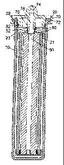
Figure 1 is a cross-section through a housing and cartridge of a water filter
in accordance with the invention, along line I-I of Figure 2;
Figure 2 is a plan view of the housing and cartridge of Figure 1;
Figure 3 is a cross-section through the water filter with the cap in place,
along line I-I of Figure 2,
Figure 4 is an underneath view of the cap; and
Figure 5 is an enlarged, partial cross-section through the water filter along
line V-V of Figure 4.
Referring to Figures 1 and 2, a housing 10, which may be integrally
moulded of plastics material, comprises a circular cross-section cylindrical
tube wall 12 closed by a bottom wall 14. A peripheral lip 16 encircles the
top, open end 18 of the tube and two opposed lugs 20 extend outwards to
form a bayonet coupling to a cap (vide hereinafter). An inner surface 22 of
wall 12, has a step 21 to form a larger diameter upper region 23, in which
two diametrically opposed recesses 24 are formed (see Figure 5).
A filter cartridge 26 is suspended in the housing 10. Cartridge 26 comprises
a circular cross-section outer sleeve 28 of porous filter material such as a
ceramic, and a circular cross-section inner sleeve 30 of porous carbon filter
material, such materials are well known in the art. Sleeve 28 is capped at

CA 02467045 2004-05-12
WO 03/042107 PCT/GB02/05100
4
its lower end 34 by a plastics base 36, and at its upper end 38 by a cap 40.
Cap 40 is supported on step 21 and has protrusions 42 which engage in the
recesses 24 in wall region 23.
Cap 40 is a loose fit in the tube 12, but dimensioned so that protrusions 42
engage with recesses 24 to ensure that the cap 40 and so the complete
cartridge 26 will rotate with the housing 10. Cap 40 has recesses 44 in its
outer periphery (Figure 2) to form channels between the cap 40 and the wall
surface 23 for water to flow into the space 46 between sleeve 28 and wall 12.
Water passes, under pressure, through sleeves 28, 30 into the inner space
48 and out through an aperture 50 in cap 40. A stub sleeve 52 surrounds
aperture 50 on the upper surface 54 of cap 40.
Also provided on the upper surface 54 of cap 40 are two cams 56. Each cam
has a sloping surface 58 leading to a flat or horizontal surface 60, i.e.
parallel to surface 54.
Referring to Figure 3, a cap 70 which may be moulded of plastics material is
fitted on the housing 10. Cap 70 has internally facing arcuate recesses 72
for receiving the lugs 20 to provide a bayonet fitting. Also seen in Figure 3
is an outlet waterway 74 which extends from the centre of the cap 70 to the
outer edge for connection to a pipe leading to a tap. Waterway 74 connects
with outlet aperture 50 via a channel 78 in a spigot 76 which is sealed to
cylinder 52 by two O-ring seal 80. Cap 70 seals with inner surface 22 of
housing 10 by an O-ring seal 82.
Figure 4 is an underneath view of cap 70 showing outlet water way 74.
Waterway 74 may be threaded at its outer end to receive a pipe connector.
Also shown is an inlet waterway 84 which extends from the outer periphery
86 of cap 70 to a spring-loaded poppet valve 88.

CA 02467045 2004-05-12
WO 03/042107 PCT/GB02/05100
Referring to Figure 5, which is a cross-section at right angles to Figure 3,
inlet waterway 84 ends in a passage 90 which connects with the space 92
above cap 40, via poppet valve 88. Valve 88 comprises a valve seat 94 which
is screwed into the cap 70, trapping a valve member 96. Valve member 96 is
biassed by a spring 98 towards valve seat 94. A conical surface 100 on
member 96 engages a surface 102 on valve seat 94 to form a seal. An O-ring
(not shown) will be interposed between surfaces 100, 102, carried loosely on
valve member 96 to form a seal.
In Figure 5, the housing 10 and cartridge 26 have been installed in the cap
and rotated to the locked position, bayonet lugs 20 abutting stops 104 (see
Figure 4) when the bayonet fitting is rotated fully home. One of the ramps
56 has lifted valve member 96 to open the valve 88, allowing water to flow.
With the cap 70 installed in-line between the water supply and a tap, when
housing 10 and cartridge 26 are removed, spring 98 and the water pressure
push valve member 96 onto valve seat 94, preventing water escaping
through passage 90. To install a filter cartridge, cartridge 26 is placed in
housing 10, the protrusions 42 and recesses 24 aligning the cartridge cap 40
and hence cams 56, relative to bayonet lugs 20. To facilitate location of the
cartridge 26 as it is 'dropped' in the housing 10, the upper inner wall region
98 is enlarged an a ramp 106 forms a junction with region 23, sloping down
to the upper end of the recesses 24. The cartridge and housing are raised in
position, lugs 20 passing between the sockets 72. The cap 70 seals against
housing 10 and cartridge 26 with '0' ring seals 80, 82. Housing 10, and
hence also cartridge 26, is then rotated to engage the bayonet lugs 20 in
sockets 72. At about 45 to 60 degrees of rotation, ramp 58 of cam 56
engages the bottom end valve member 96. At 60 to 90 degrees rotation, the
cam 56 has lifted valve member 96 so that it rests on flat surface 60 of cam
56, and is fully open, as seen in Figure 5.

CA 02467045 2004-05-12
WO 03/042107 PCT/GB02/05100
6
By providing a rotationally symmetric fitting, the cartridge 26 can be fitted
in either of two positions in housing 10, and housing 10 can engage cap 70 in
either of two positions. It will be appreciated that the shapes may be
altered to ensure that the parts always engage in one configuration only, or
in more than two.
The cartridge 26 may be keyed to the housing 10 in other ways.
Other modifications will be apparent to those skilled in the art.

Representative Drawing
A single figure which represents the drawing illustrating the invention.
Administrative Status

2024-08-01:As part of the Next Generation Patents (NGP) transition, the Canadian Patents Database (CPD) now contains a more detailed Event History, which replicates the Event Log of our new back-office solution.

Please note that "Inactive:" events refers to events no longer in use in our new back-office solution.

For a clearer understanding of the status of the application/patent presented on this page, the site Disclaimer , as well as the definitions for Patent , Event History , Maintenance Fee  and Payment History  should be consulted.

Event History

Description Date
Inactive: IPC expired 2023-01-01
Application Not Reinstated by Deadline 2007-11-13
Time Limit for Reversal Expired 2007-11-13
Deemed Abandoned - Failure to Respond to Maintenance Fee Notice 2006-11-14
Inactive: IPC from MCD 2006-03-12
Inactive: First IPC assigned 2004-12-20
Inactive: IPC assigned 2004-12-20
Letter Sent 2004-09-09
Inactive: Single transfer 2004-08-09
Inactive: Courtesy letter - Evidence 2004-07-20
Inactive: Cover page published 2004-07-16
Inactive: Notice - National entry - No RFE 2004-07-14
Application Received - PCT 2004-06-15
National Entry Requirements Determined Compliant 2004-05-12
Application Published (Open to Public Inspection) 2003-05-22

Abandonment History

Abandonment Date Reason Reinstatement Date
2006-11-14

Maintenance Fee

The last payment was received on 2005-10-24

Note : If the full payment has not been received on or before the date indicated, a further fee may be required which may be one of the following

  • the reinstatement fee;
  • the late payment fee; or
  • additional fee to reverse deemed expiry.

Please refer to the CIPO Patent Fees web page to see all current fee amounts.

Fee History

Fee Type Anniversary Year Due Date Paid Date
Basic national fee - standard 2004-05-12
MF (application, 2nd anniv.) - standard 02 2004-11-12 2004-05-12
Registration of a document 2004-08-09
MF (application, 3rd anniv.) - standard 03 2005-11-14 2005-10-24
Owners on Record

Note: Records showing the ownership history in alphabetical order.

Current Owners on Record
AVILION LIMITED
Past Owners on Record
GREGORY NORMAN ROWE
ROBERT BRYAN PERRIN
Past Owners that do not appear in the "Owners on Record" listing will appear in other documentation within the application.
Documents

To view selected files, please enter reCAPTCHA code :


To view images, click a link in the Document Description column. To download the documents, select one or more checkboxes in the first column and then click the "Download Selected in PDF format (Zip Archive)" or the "Download Selected as Single PDF" button.

List of published and non-published patent-specific documents on the CPD .

If you have any difficulty accessing content, you can call the Client Service Centre at 1-866-997-1936 or send them an e-mail at CIPO Client Service Centre.


Document
Description 
Date
(yyyy-mm-dd) 
Number of pages   Size of Image (KB) 
Drawings 2004-05-12 3 94
Description 2004-05-12 6 229
Abstract 2004-05-12 2 77
Claims 2004-05-12 2 55
Representative drawing 2004-07-16 1 17
Cover Page 2004-07-16 1 45
Notice of National Entry 2004-07-14 1 193
Courtesy - Certificate of registration (related document(s)) 2004-09-09 1 129
Courtesy - Abandonment Letter (Maintenance Fee) 2007-01-09 1 175
Reminder - Request for Examination 2007-07-16 1 119
PCT 2004-05-12 7 264
Correspondence 2004-07-14 1 25