Note: Descriptions are shown in the official language in which they were submitted.
CA 02467224 2004-05-13
APPARATUS FOR DETERMINING SHAPING RATE
AND
METHOD OF DOING THE SAME
BACKGROUND OF THE INVENTION
FIELD OF THE INVENTION
The invention relates to an apparatus for determining a shaping rate,
a system for doing the same, a method of doing the same, and a program for
causing a computer to carry out the method.
DESCRIPTION OF THE RELATED ART
In conventional QoS (quality of service) technology, priority control and
band control are carried out by network devices to thereby earlier transmit
packets having a higher priority and narrow a band of an output interface,
ensuring enhancement in communication quality in Internet and Intranet.
However, in a best-effort type network in which a band is not
guaranteed, if a band of an actually using channel becomes smaller than a
shaping rate, packets might by abandoned in the network regardless of a
priority
of the packets.
For instance, Japanese Patent Application Publication No.
2001-168871(A) has suggested a data transmission system in which when a
lower-layer protocol has data indicative of a rate at which data can be
transmitted from a network, an upper-layer protocol transmits packets at the
rate indicated in the data.
Japanese Patent Application Publication No. 2002-217960(A) has
suggested an IP-packet router which avoids a problem of concentration of
packets
to a particular processor to ensure that IP-packets are smoothly routed.
Japanese Patent Application Publication No. 2002-247092(A) has
suggested a system for determining a band in a communication terminal acting
1
CA 02467224 2004-05-13
as a node in a connectionless network. The system automatically sets a band to
match to bands of all of the communication terminals arranged in a common
network.
Japanese Patent Application Publication No. 10-145383(A) has
suggested a shaping circuit which controls a period of time necessary for
transmission of a next cell, in accordance with a reference shaping time as a
reference period of time, and controls cell transmission in accordance with
the
period of time. The reference shaping time is determined in the range of 0% to
100%.
Japanese Patent Application Publication No. 11-317743(A) has
suggested a scheduler which schedules a stream queue supplying cells having
QoS conditions different from one another, and shapes a transmission rate such
that congestion in a bottleneck in an ATM switch avoids.
Japanese Patent No. 2910746(B2) (Japanese Patent Application
Publication No. 11-112511(A)) has suggested a method of traffic-shaping,
including controlling a rate of an ATM cell transmitted from an ATM network
device, applying a frame period to the ATM cell, and monitoring a transmission
rate of the ATM cell.
Japanese Patent Application Publication No. 2000-49787(A) has
suggested a band division system in which when a band is assigned to a
plurality
of connections, bands actually transmitted from a terminal device are divided
to
each of the connections in accordance with a priority of each of the
connections.
Japanese Patent Application Publication No. 2000-101608(A) has
suggested a shaping method for converting an input data flow of a rate of an
input data packet into an output data flow of a rate of an output data packet.
Japanese Patent Application Publication No. 2000-115191(A) has
suggested a shaping device including a shaper which buffers received data cell
for
each of kinds of data cell connection, and transmits the buffered data cell in
accordance with a transmission rate defined for each of data cell connection,
and
2
CA 02467224 2004-05-13
a data transmitter which detects a sub-congestion condition just short of a
congestion condition in which next data cell has to be abandoned in accordance
with a number of data cell having been buffered for each of kinds of data cell
connection, and a non-congestion condition, and transmits results of the
detection
to a device for transmitting data cell.
Japanese Patent Application Publication No. 2000-253056(A) has
suggested a transmission-band controller in a data transmission device which
makes communication with network, including a data buffer temporarily storing
transmission data, first means for adding cer.tain protocol data to the
transmission data and transmitting the transmission data to the network,
second
means for transferring data at a predetermined interval for every certain
volume
of data between the data buffer and the first means, and varying the volume of
data and the interval, and third means for calculating an interval at which
the
second means transmits data, based on both data indicative of a volume of data
to be transmitted in a certain period of time and the certain volume of data,
and
indicating the calculated interval to the second means.
Japanese Patent Application Publication No. 2001-77819(A) has
suggested a method of solving an address used when data is transmitted between
first and second networks, including the steps of ass:igning a priority to
data to be
transmitted to the second network from the first network, monitoring wires in
the second network, determining a transmission route and a transmission rate
for transmitting data through the second network, varying a transmission rate
of
data having a low priority among data transmitted through the wires, when a
rate at which the wires in the determined transmission route is over a
threshold
by transmitting the data, and re-arranging the wires in accordance with the
varied transmission rate.
Japanese Patent Application Publication No. 2001-268118(A) has
suggested a system for transmitting packets, including a node system through
which a data packet passes, the data packet having a header including data
3
CA 02467224 2004-05-13
indicative of a band necessary for communication through the use of the data
packet, the node system including first means for receiving a data packet,
second
means for reading a header of the received data packet, and third means for
judging whether a band necessary for making communication through the use of
the data packet can be ensured based on the read-out header.
However, the systems and the router suggested in the above-mentioned
Publications are accompanied with a problem of poor communication quality,
because a usable band varies in accordance with a place, a time and/or a
provider
in a best-effort type network in which a band is not guaranteed.
SUMMARY OF THE INVENTION
In view of the above-mentioned problem in the conventional systems, it
is an object of the present invention to provide an apparatus for determining
a
shaping rate which apparatus is capable of automatically determining a band of
an output interface of a communication terminal in accordance with a band in a
best-effort type network such as Internet in which a band is not guaranteed.
It is also an object of the present invention to provide a system for
doing the same.
It is further an object of the present invention to provide a method of
doing the same.
It is further an object of the present invention to provide a program for
causing a computer to carry out the method.
Hereinbelow is described the above-mentioned apparatus, system,
method and program in accordance with the present invention through the use of
reference numerals used in later described embodiments. The reference
numerals are indicated only for the purpose of clearly showing correspondence
between claims and the embodiments. It should be noted that the reference
numerals are not allowed to use in the interpretation of claims of the present
application.
4
CA 02467224 2008-05-08
76319-12
In one aspect of the present invention, there is provided an apparatus
for determining a shaping rate, to inake communication with a communication
terminal through a best-effort type network, including a Ping transmitter
(201)
transmitting at least one Ping packet used for measuring a band, and Ping data
indicative of the Ping packet, a first controller (202) receiving the Ping
packet
from the Ping transmitter (201) and transmitting' the Ping packet in
accordance
with a priority thereof, a judgment unit (206) receiving the Ping data from
the
Ping transmitter (201), and a second controller (203) determining a shaping
rate and shaping
the Ping packet received from the first controller (202) independent of said
judgment unit,
wherein the judgment unit (206) makes band data indicative of an actually
usable band,
based on a response received from 'the communication terminal (103, 303) and
the Ping data received from the Ping transmitter (201), and transmits the band
data to the second controller (203), and the second controller (203) varies a
shaping rate in accordance with the band data received from the judgment unit
(206).
The apparatus may furthe:r include a packet transmitter (204) through
which the Ping packet is transmitted to the communication terminal from the
second controller (203).
The apparatus may further include a packet receiver (205) which
receives the response from the communication terminal and transmits the
received response to the judgment unit (206).
It is preferable that the Pir.ig transmitter (201) determines a number of
Ping packets to be transmitted therefrom, and a packet size.
It is preferable that the Ping transmitter (201) transmits a control
packet in place of the Ping packet.
It is preferable that the Ping packet measures a band of a
communication terminal (40) disposed. in a provider (403).
It is preferable that the first controller (202) assigns a
minimum-guaranteed band to each of classes.
5
CA 02467224 2008-05-08
76319-12
It is preferable that the first controller (202) inserts the Ping packet
received from the Ping transmitter (2;01) and other packets into separate
classes.
It is preferable that the first controller (202) assigns a
minimum-guaranteed band to a class through which the Ping packet passes
which band is lower than a minimuin-guaranteed band to be assigned to a class
through which the packets passes.
It is preferable that the second controller, (203) determines a maximum
shaping rate among shaping rates at which the Ping packet is transmitted from
the second controller (203).
It is preferable that the Ping transmitter (201) determines an interval
at which the actually usable band is measured.
In another aspect of the present invention, there is provided an
apparatus for determining a shaping rate, to make communication with a
communication terminal through a best-effort type network, including a packet
transmitter (701) transmitting at least one control packet used for measuring
a
band, a first controller (702) receiving the control packet from the packet
transmitter (701) and transmitting; the control packet in accordance with a
priority thereof, and a second controller (70:3) determining a shaping rate
and shaping the
control packet received from the first controller (702) independent of said
judgment unit,
wherein the second controller (703) receives band data indicative of an
actually usable band,
from the communication terminal (503), and varies a shaping rate in accordance
with the band data.
It is preferable that the packet transmitter (701) determines a number
of control packets to be transmitted therefrom, and a packet size.
It is preferable that the second controller (703) determines a maximum
shaping rate among shaping rates at which the control packet is transmitted
from the second controller (703).
It is preferable that the packet transmitter (701) determines an
interval at which the actually usable band is measured.
6
CA 02467224 2008-05-08
76319-12
In another aspect of the present invention, there
is provided a method of deter-mining a shaping rate at which
communication is made with a communication terminal through
a best-effort type network, comprising: transmitting at
least one Ping used for measuring a band, and Ping data
indicative of said Ping from a first controller to a second
controller independent of a judgment unit; shaping said
Ping; transmitting the shapec. Ping to said communication
terminal; receiving a response from said communication
terminal; making band data indicative of an actually usable
band, based on said response and said Ping data, said band
data being made by said judgment unit; and varying said
shaping rate in accordance with said band data.
The method may further include determining an
interval at which the band is to be measured, and varying
the shaping rate at the interval.
There is further provided a method of determining
a shaping rate at which communication is made with a
communication terminal throug;Z a best-effort type network,
comprising: transmitting at least one control packet used
for measuring a band from a f:irst controller to a second
controller independent of a judgment unit; shaping said
control packet; transmitting the shaped control packet to
said communication terminal; receiving band data indicative
of an actually usable band, from said communication
terminal; making band data indicative of an actually usable
band, based on said band data, said band data being made by
said judgment unit; and varyirig said shaping rate in
accordance with said band data.
The method may furtr.er include determining an
interval at which the band is to be measured, and varying
the shaping rate at the interval.
7
CA 02467224 2008-05-08
76319-12
In still another aspect of the present invention,
there is provided a computer readable medium having computer
readable program code stored thereon for execution by one or
more computers, that when executed implement a method of
determining a shaping rate at. which communication is made
with a communication terminal. through a best-effort type
network, the method comprising: transmitting at least one
Ping used for measuring a bar..d, and Ping data indicative of
said Ping from a first controller to a second controller
independent of a judgment unit; shaping said Ping;
transmitting the shaped Ping to said communication terminal;
receiving a response from said communication terminal;
making band data indicative of an actually usable band,
based on said response and said Ping data, said band data
being made by said judgment unit; and varying said shaping
rate in accordance with said band data.
It is preferable that the steps further include
determining an interval at which the band is to be measured,
and varying the shaping rate at the interval.
There is further provided a computer readable
medium having computer readable program code stored thereon
for execution by one or more computers, that when executed
implement a method of determining a shaping rate at which
communication is made with a communication terminal through
a best-effort type network, the method comprising:
transmitting at least one control packet used for measuring
a band from a first controller to a second controller
independent of a judgment unit; shaping said control packet;
transmitting the shaped control packet to said communication
terminal; receiving band data indicative of an actually
usable band, from said communication terminal; making band
data indicative of an actually usable band, based on said
band data, said band data beirig made by said judgment unit;
8
CA 02467224 2008-05-08
76319-12
and varying said shaping rate in accordance with said band
data.
It is preferable that the steps further include
determining an interval at which the band is to be measured,
and varying the shaping rate at the interval.
In yet another aspect of the present invention,
there is provided a system for determining a shaping rate,
comprising an apparatus for cletermining a shaping rate, at
least one communication terminal, and a best-effort type
network through which the apparatus and the communication
terminal make communication with each other, wherein the
apparatus includes a Ping transmitter transmitting at least
one Ping used for measuring a band, and Ping data indicative
of the Ping, a first controller receiving the Ping from the
Ping transmitter and transmitting the Ping in accordance
with a priority thereof, a judgment unit receiving the Ping
data from the Ping transmitter, and a second controller
determining a shaping rate and shaping the Ping received
from the first controller, wherein the judgment unit makes
band data indicative of an actually usable band, based on a
response received from the communication
8a
CA 02467224 2004-05-13
terminal and the Ping data received from the Ping transmitter, and transmits
the
band data to the second controller, and the second controller varies a shaping
rate in accordance with the band data received from the judgment unit.
There is further provided a system for determining a shaping rate,
comprising an apparatus for determining a shaping rate, at least one
communication terminal, and a best-effort type network through which the
apparatus and the communication terminal make communication with each other,
wherein the apparatus includes a packet transmitter transmitting at least one
control packet used for measuring a band, a first controller receiving the
control
packet from the packet transmitter and transmitting the control packet in
accordance with a priority thereof, and a second controller determining a
shaping
rate and shaping the control packet received from the first controller,
wherein the
second controller receives band data indicative of an actually usable band,
from
the communication terminal, and varies a shaping rate in accordance with the
band data.
The advantages obtained by the aforementioned present invention will
be described hereinbelow.
Though a usable band varies in accordance with a place, a time and/or
a provider in a best-effort type network in which a band is not guaranteed,
the
apparatus, system, method and program in accordance with the present
invention make it possible to periodically measure a band of a usable channel,
and automatically change a band of network devices, ensuring enhancement in
quality of communication.
The above and other objects and advantageous features of the present
invention will be made apparent from the following description made with
reference to the accompanying drawings, in which like reference characters
designate the same or similar parts throughout the drawings.
9
CA 02467224 2008-05-08
76319-12
BRIEF DESCRIPTION OF THE DRp-WINGS
FIG. 1 illustrates a netivork system including a best-effort type
network.
FIG. 2A is a block diagram of an apparatus for determining a shaping
rate, in accordance with the first embodiment of the present invention.
FIG. 2B is a block diagrana of the first controller in the apparatus in
accordance with the first embodiment;.
FIG. 3 illustrates an example of a network system in which the
apparatus in accordance with the first embodiment is used.
FIG. 4 illustrates communication made after a shaping rate has been
varied in the first embodiment.
FIG. 5 illustrates an example of a network system in which the
apparatus in accordance with the second embodiment is used.
FIG. 6 illustrates an example of a network system in which the
apparatus in the apparatus in accordance with the third embodiment is used.
FIG. 7 is a block diagram of an apparatus for determining a shaping
rate, in accordance with the third embodiment of the present invention.
FIG. 8 is a block diagram of a communication terminal in the third
embodiment of the present invention.
DESCRIPTION OF THE PREFERRED EMBODIMENTS
Preferred embodiments in accordance with the present invention will
be explained hereinbelow with reference to drawings.
[First Embodiment]
FIG. 1 illustrates a network system including a best-effort type
network.
As illustrated in FIG. 1, a first communication terminal 101 is
designed to make communication with a second communication terminal 103
through a best-effort type network 102. The first communication terminal 101
CA 02467224 2004-05-13
is connected to a first LAN 101A, and the second communication terminal 103 is
connected to a second LAN 103A.
The first communication terminal 101 includes an apparatus 105 for
determining a shaping rate, in accordance with the first embodiment of the
present invention.
FIG. 2A is a block diagram of the apparatus 105 for determining a
shaping rate. The apparatus 105 controls a band (a shaping rate) of an output
interface of the first communication terminal 101 through the use of Ping
(packet
internet groper) in accordance with a band of the best-effort type network 102
in
which a band is not guaranteed. The apparatus 105 may use a control packet in
place of Ping to control a band of an output interface of the first
communication
terminal 101.
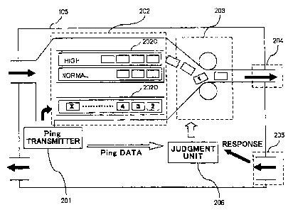
As illustrated in FIG. 2A, the apparatus 105 is comprised of a Ping
transmitter 201 which transmits Ping packets used for measuring a band, and
Ping data indicative of the Ping packets, a first controller 202 which
receives
Ping packets from the Ping transmitter 201 and transmits the received Ping
packets in accordance with a priority thereof, a second controller 203 which
determines a shaping rate and shapes the Ping packets received from the first
controller 202, in accordance with the determined shaping rate, a packet
transmitter 204 through which the Ping packets are transmitted to the second
communication terminal 103 from the second controller 203, a packet receiver
205 which receives a response packet from the second communication terminal
103 and transmits the received response packet to a later mentioned judgment
unit 206, and a judgment unit 206 which receives the Ping data from the Ping
transmitter 201, and the response packet from the packet receiver 205.
The Ping transmitter 201 transmits Ping packets to the first controller
202, and further transmits Ping data indicative of the Ping packets
transmitted
to the first controller 202, to the judgment device 206. A number the Ping
packets to be transmitted to the first controller 202, and a packet size of a
Ping
11
CA 02467224 2004-05-13
are determined in advance. In place of a Ping, there may be used a control
packet for measuring a band.
FIG. 2B is a block diagram of the first controller. 202.
As illustrated in FIG. 2B, the first controller 202 is comprised of a
central processing unit 202A and a memory 202B.
The memory 202B is comprised of a semiconductor memory such as a
read only memory (ROM), a random access memory (RAM) or an IC memory card,
or a storage device such as a flexible disc, a hard disc or an optic magnetic
disc.
In the first embodiment, the memory 202B is comprised of a read only memory
(ROM).
The memory 202B stores therein a control program for driving the
central processing unit 202A. The central processing unit 202A reads the
program out of the memory 202B, and executes the program. Thus, the central
processing unit 202A operates in accordance with the program stored in the
memory 202B.
The first controller 202 carries out class base queuing (CBQ) control as
priority control. Specifically, the first controller 202 assigns a minimum
guaranteed band to each of classes in accordance with a priority of each of
the
packets. As illustrated in FIG. 2A, the first controller 202 defines a first
class
202C through which data packets pass, and a second class 202D through which
Ping packets pass. The first controller 202 receives data packets having a
high
or normal priority, and further receives Ping packets 1 to X from the Ping
transmitter 201. The first controller 202 transmits the received data packets
to
the second controller 203 through the first class 202C, and transmits the
received
Ping packets 1 to X to the second controller 203 through the second class
202D.
The Ping packets are transmitted to the second controller 203 in preference to
the data packets. The data packets having a high priority are transmitted to
the second controller 203 in preference to the data packets having a normal
priority.
12
CA 02467224 2004-05-13
Though not illustrated, the second controller 203 is comprised of a
central processing unit and a memory, similarly to the first controller 202.
The memory is comprised of a read only memory (ROM), and stores
therein a control program for driving the central processing unit. The central
processing unit reads the program out of the memory, and executes the program.
Thus, the central processing unit operates in accordance with the program
stored
in the memory.
In the first embodiment, the first and second controllers 202 and 203
are designed to include separate central processing units, however, the first
and
second controllers 202 and 203 may be designed to include a common central
processing unit.
The second controller 203 determines a certain shaping rate. The
second controller 203 narrows a band in accordance with the shaping rate, and
transmits the packets to the packet transmitter 204.
The packets including Ping packets are transmitted to the second
communication terminal 103 through an output interface of the first
communication terminal 101.
On receipt of the packets from the first communication terminal 101,
the second communication terminal 103 transmits a response packet to the first
communication terminal 101 in response to the Ping packets.
The apparatus 105 in the first commuxiication terminal 101 receives
the response packet from the second communication terminal 103 through the
packet receiver 205. The received response packet is transmitted to the
judgment unit 206.
On receipt of the response packet from the second communication
terminal 103 and the Ping data from the Ping transmitter 201, the judgment
unit
206 makes band data indicative of an actually usable band, based on the
response packet and the Ping data. Then, the judgment unit 206 transmits the
band data to the second controller 203.
13
CA 02467224 2004-05-13
The second controller 203 varies a shaping rate in accordance with the
band data received from the judgment unit 206. If the Ping transmitter 201
determines an interval at which a band is measured, a usable band is
periodically measured, and thus, a shaping rate is periodically varied by the
second controller 203.
As mentioned above, the apparatus 105 in accordance with the first
embodiment measures a band of the best-effort type network 102 through the use
of Ping packets, and automatically and periodically adjusts a band of an
output
interface of the first communication terminal 101 in accordance with an
actually
usable band. Hence, the apparatus provides enhancement in communication
quality.
For measuring a band, a control packet may be used in place of a Ping
packet.
Hereinbelow is explained a process of automatically varying a shaping
rate in the apparatus 105 in communication made through a best-effort type
network.
FIG. 3 illustrates an example of a network system in which the
apparatus 105 in the apparatus in accordance with the first embodiment is
used.
As illustrated in FIG. 3, a first router 301 makes communication with a
second router 303 through an ADSL modem 304 and Internet 302. The first
router 301 is connected to a first network (not illustrated) through a first
LAN
301A, and the second router 303 is connected to a second network (not
illustrated) through a second LAN 303A. The first and second networks make
communication with each other.
A band of an output interface of the first router 301 is automatically
controlled as follows.
The first router 301 is designed to include the apparatus 105
illustrated in FIG. 2A.
On receipt of a Ping packet from the first router 301, the second router
14
CA 02467224 2004-05-13
303 transmits a response packet to the first router 301 through Internet 302
and
the ADSL modem 304.
It is assumed hereinbelow that a best-effort type network defined
between the ADSL modem 304 and Internet 302 ensures a band of 1 Mbps at
greatest in an up-channel, but an actually usable band is just 0.8 Mbps.
The Ping transmitter 201 transmits a predetermined number of Ping
packets to the first controller 202. Each of the Ping packets has a
predetermined packet size. The Ping transmitter 201 further transmits data
about the Ping packets transmitted to the first controller 202, to the
judgment
unit 206.
The first controller 202 carries out priority control or class base
queuing (CBQ) control to the received packets. Specifically, the first
controller
202 assigns a minimum- guaranteed band to each of classes in accordance with a
priority of each of the classes. As illustrated in FIG. 2A, the first
controller 202
transmits the received data packets to the second controller 203 through the
first
class 202C, and transmits the received Ping packets 1 to X to the second
controller 203 through the second class 202D. The Ping packets are transmitted
to the second controller 203 in preference to the data packets. The data
packets
having a high priority are transmitted to the second controller 203 in
preference
to the data packets having a normal priority.
In order to exert less influence on other communication, a
minimum-guaranteed band assigned to the second class 202D through which the
Ping packets pass is set lower than a minimum-guaranteed band assigned to the
first class 202C through which the data packets pass.
The second controller 203 determines a maximum band (shaping rate)
among bands at which packets are transmitted to the second router 303 through
an output interface of the first router 301. Since the maximum band of 1 Mbps
is ensured in an up-channel, the second controller 203 determines a shaping
rate
to be equal to 1 Mbps.
CA 02467224 2004-05-13
The first controller 202 carries out the above-mentioned priority
control to the data packets receiving for other communication and the Ping
packets. The Ping packets are transmitted to the second controller 203 from
the
first controller 202, and then, shaped in accordance with a shaping rate
determined in advance. Then, the Ping packets are transmitted to the packet
transmitter 204. Then, the Ping packets as well as the other data packets are
transmitted to the second router 303 through an output interface of the first
router 301.
The packets including the Ping packets are transmitted to the second
router 303 through the ADSL modem 304 and Internet 302. Since a channel
between the ADSL modem 304 and Internet 302 is a part of a best-effort type
network in which a band is not guaranteed, the ADSL modem 304 may transmit
packets at a band equal to or smaller than the shaping rate of 1 Mbps having
been determined by the second controller 203 in the first router 301.
In FIG. 3, it is assumed that an actually usable band is 0.8 Mbps.
Accordingly, a part of the packets is abandoned in the ADSL modem 304
regardless of a priority of the packets or whether a packet is a Ping packet
or not.
Specifically, the packets equivalent to 0.2 Mbps (1-0.8 = 0.2) are abandoned.
On receipt of the packets, the second router 303 transmits a response
packet indicating of receipt of the Ping packet, to the first router 301.
FIG. 3 illustrates a case in which the first router 301 transmits twenty
(20) Ping packets to the second router 303, four (4) Ping packets are
abandoned
in the ADSL modem 304, sixteen (16) Ping packets reach the second router 303,
and the second router 303 transmits a response packet indicating that the
second
router 303 has received sixteen Ping packets, to the first router 301.
The response packet is transmitted to the judgment unit 206 through
the packet receiver 205 in the first router 301.
On receipt of the response packet transmitted from the second
communication terminal 103 and the Ping data transmitted from the Ping
16
CA 02467224 2004-05-13
transmitter 201, the judgment unit 206 makes band data indicative of an
actually usable band, based on the response packet and the Ping data. Then,
the judgment unit 206 transmits the band data to the second controller 203.
Then, the second controller 203 varies a shaping rate in accordance
with the band data received from the judgment unit 206.
FIG. 4 illustrates communication between the first and second routers
301 and 303 made after a shaping rate of an output interface in the first
router
301 has been varied.
The packets transmitted from the first router 301 reach the second
router 303 without being abandoned in the best-effort type network in which a
band is not guaranteed. The first router 301 periodically measures a band, and
automatically optimizes a shaping rate.
A usable band varies in accordance with a place, a time and/or a
provider in the best-effort type network 102 in which a band is not
guaranteed.
The apparatus 105 in accordance with the first embodiment periodically
measures a usable band of the best-effort type network 102 through the use of
Ping packets, and automatically and periodically adjusts a band of an output
interface of the first communication terminal 101 in accordance with the
measured usable band. Hence, the apparatus 105 provides enhancement in
communication quality.
[Second Embodiment]
FIG. 5 illustrates an example of a network system in which the
apparatus in accordance with the second embodiment is used.
As illustrated in FIG. 5, a router 401 makes communication with
Internet 405 through a communication terminal 402 such as BAS of a provider
403. The router 401 makes communication with a network (not illustrated)
through LAN 401A.
The router 401 includes the apparatus 105 illustrated in FIG. 2A.
Accordingly, a process of automatically controlling a band of an output
interface
].7
CA 02467224 2004-05-13
of the router 401 is identical with the process having been explained in the
first
embodiment.
The network (not illustrated) to which the router 401 is connected
through LAN 401A and Internet 405 makes communication with each other
through the communication terminal 402. Any terminal can make access to a
communication terminal 404 disposed in Internet 405.
On receipt of packets including Ping packets from the router 401, the
communication terminals 402 and 404 transmits a response indicating that they
have received a Ping packet, to the router 401.
Hereinbelow is explained an operation of the second embodiment.
In FIG. 5, the router 401 and Internet 405 make communication with
each other through a best-effort type network in which a band is not
guaranteed.
A process of automatically controlling a band of an output interface of the
router
401 is identical with the process having been explained in the first
embodiment.
By directing a Ping packet transmitted from the router 401 to the
communication terminal 402 disposed in the provider 403 or the communication
terminal 404 disposed in Internet 405, it would be possible to automatically
vary
a band of an output interface of the router 401, even if the router 401 makes
communication with Internet 405.
In the second embodiment, Internet 405 is a best-effort type network in
which a band is not guaranteed, and packets not to be abandoned may be
abandoned in a channel between the router 401 and the provider 403 or in a
channel between the provider 403 and Internet 405. The apparatus in
accordance with the second embodiment periodically measures a usable band in a
channel between the router 401 and the communication terminal 402 or 404, and
automatically varies a band of an output interface of the router 401, ensuring
enhancement in communication quality.
[Third Embodiment]
FIG. 6 illustrates an example of a network system in which the
18
CA 02467224 2004-05-13
apparatus in accordance with the third embodiment is used.
As illustrated in FIG. 6, a first comrnunication terminal 501 is
designed to make communication with a second communication terminal 503
through a best-effort type network 502 in which a band is not guaranteed. The
first communication terminal 501 is connected to a first LAN 501A, and the
second communication terminal 503 is connected to a second LAN 503A.
The first communication terminal 501 includes an apparatus 700 for
determining a shaping rate, in accordance with the third embodiment. The
apparatus 700 measures a band through the use of a control packet in place of
a
Ping packet.
FIG. 7 is a block diagram of the apparatus 700 for determining a
shaping rate.
As illustrated in FIG. 7, the apparatus 700 is comprised of a packet
transmitter 701 which transmits control packets used for measuring a band, a
first controller 702 which receives control packets from the packet
transmitter
701 and transmits the received control packets in accordance with a priority
thereof, a second controller 703 which determines a shaping rate and shapes
the
control packets received from the first controller 702, in accordance with the
determined shaping rate, a packet transmitter 704 through which the control
packets are transmitted to the second communication terminal 503 from the
second controller 703, a packet receiver 705 which receives a response packet
from the second communication terminal 503 and transmits the received
response packet to the second controller 703.
The packet transmitter 701, the first controller 702, the second
controller 703, the packet transmitter 704, and the packet receiver 705
correspond to the packet transmitter 201, the first controller 202, the second
controller 203, the packet transmitter 204, and the packet receiver 205 in the
apparatus 105 in accordance with the first embodiment, illustrated in FIG. 2A.
In comparison with the apparatus 105 illustrated in FIG. 2A, the
19
CA 02467224 2004-05-13
apparatus 700 illustrated in FIG. 7 does not include a unit corresponding to
the
judgment unit 206.
An operation of the apparatus 700 is explained hereinbelow.
The packet transmitter 701 transmits control packets to the first
controller 702. The control packets transmitted to the first controller 702
includes data indicative of a number and a size of control packets to be
transmitted to the first controller 702. In the third embodiment, the control
packet is comprised of a UDP packet to which a re-transmission control is not
necessary to carry out.
FIG. 8 is a block diagram of the second communication termina1503.
The second communication terminal 503 is comprised of a
control-packet receiver 601 and a band-data transmitter 602. The second
communication terminal 503 receives a control packet from the first
communication terminal 501 through the control-packet receiver 601. The
control-packet receiver 601 takes data 603 indicative of a number of the
received
control packets and other various data 604, out of the received control
packets,
and transmits the data 603 and 604 to the band-data transmitter 602.
On receipt of the data 603 and 604 from the control-packet receiver 601,
the band-data transmitter 602 calculates a band, based on the data 603 and
604.
Then, the band-data transmitter 602 transmits data indicative of the
calculated band, to the first communication terminal 501.
The first communication terminal 501 receives the band data from the
second communication terminal 503 through the packet receiver 705, and then,
transmits the received band data to the second controller 703.
On receipt of the band data from the packet receiver 705, the second
controller 703 varies a shaping rate in accordance with the received band
data.
A usable band varies in accordance with a place, a time and/or a
provider in the best-effort type network 502 in which a band is not
guaranteed.
The apparatus 700 in accordance with the third embodiment periodically
CA 02467224 2004-05-13
measures a usable band in the best-effort type network 502 through the use of
control packets, and automatically and periodically adjusts a band of an
output
interface of the first communication terminal 501 in accordance with the
measured usable band. Hence, the apparatus 700 provides enhancement in
communication quality.
In addition, since a band is measured through the use of a control
packet, the second communication terminal 503 is required to transmit only one
control packet as a response to the first communication terminal 501. This
ensures reduction in a burden in the second communication terminal 503 and the
network 502 through which a control packet as a response passes.
While the present invention has been described in connection with
certain preferred embodiments, it is to be understood that the subject matter
encompassed by way of the present invention is not to be limited to those
specific
embodiments. On the contrary, it is intended for the subject matter of the
invention to include all alternatives, modifications and equivalents as can be
included within the spirit and scope of the following claims.
21