Language selection

Search

Patent 2467303 Summary

Third-party information liability

Some of the information on this Web page has been provided by external sources. The Government of Canada is not responsible for the accuracy, reliability or currency of the information supplied by external sources. Users wishing to rely upon this information should consult directly with the source of the information. Content provided by external sources is not subject to official languages, privacy and accessibility requirements.

Claims and Abstract availability

Any discrepancies in the text and image of the Claims and Abstract are due to differing posting times. Text of the Claims and Abstract are posted:

  • At the time the application is open to public inspection;
  • At the time of issue of the patent (grant).
(12) Patent: (11) CA 2467303
(54) English Title: ROTARY BENDING TOOL AND METHOD OF MANUFACTURE
(54) French Title: OUTIL A CINTRER ROTATIF ET METHODE DE FABRICATION
Status: Granted
Bibliographic Data
(51) International Patent Classification (IPC):
  • B21D 5/02 (2006.01)
(72) Inventors :
  • CHUN, VICTOR (United States of America)
  • MADEJ, FRANK (United States of America)
(73) Owners :
  • ANCHOR LAMINA AMERICA, INC. (United States of America)
(71) Applicants :
  • DANLY IEM, DIVISION OF CONNELL LIMITED PARTNERSHIP (United States of America)
(74) Agent: MACRAE & CO.
(74) Associate agent:
(45) Issued: 2008-06-17
(22) Filed Date: 2004-05-14
(41) Open to Public Inspection: 2005-02-01
Examination requested: 2004-08-23
Availability of licence: N/A
(25) Language of filing: English

Patent Cooperation Treaty (PCT): No

(30) Application Priority Data:
Application No. Country/Territory Date
10/632,692 United States of America 2003-08-01

Abstracts

English Abstract

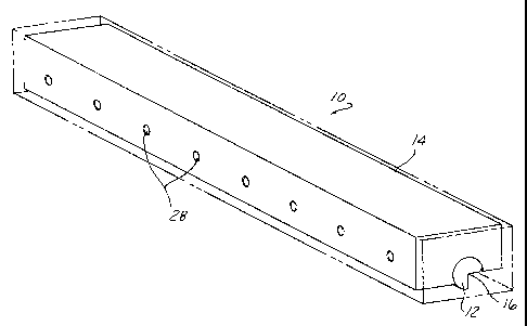
A rotary bending tool having a series of graphite plugs mounted in a saddle recess engaging a rocker surface to lubricate the same. The rocker is machined in an unhardened state and thereafter heat treated to be hardened, with reverse bending of the rocker thereafter carried out to correct any warpage.


French Abstract

Un outil à cintrer rotatif possède une série de bouchons de graphite fixés dans un évidement en forme de selle en prise avec une surface de culbuteur pour en assurer la lubrification. Le culbuteur est usiné dans un état non trempé et est par la suite traité thermiquement pour être trempé, suivi du cintrage inverse du culbuteur pour corriger tout gauchissement.

Claims

Note: Claims are shown in the official language in which they were submitted.


Claims


1. A rotary bending tool, comprising:

a saddle comprised of an elongated member formed with a partially cylindrical
open recess extending lengthwise along said saddle;

a rocker comprised of an elongated member having a partially cylindrical outer

surface fit to said partially cylindrical portion of said saddle recess, said
saddle recess to allow
relative rotation therein, said saddle partially encircling said rocker to
capture the same;

said rocker having a V-shaped recess extending lengthwise along said rocker,
said
V-shaped recess positioned to face away from said saddle recess with said
cylindrical saddle
recess and said partially cylindrical surface of said rocker interfit
together;

a series of pins each received in respective one of a series of holes in said
saddle
and entering a respective one of a series of pockets formed into said
cylindrical surface of said
rocker;

a spring associated with each pin holding said pin in said respective pocket
of said
rocker;

a series of oil impregnated graphite plugs mounted into a surface defining
said
saddle recess and engaging said rocker cylindrical surface, said series
distributed along the length
of said saddle recess, lubricating said rocker cylindrical surfaces.

2. The rotary bending tool according to claim I wherein said series of
graphite plugs are arranged in two side by side rows extending along said
saddle recess.


3. The rotary bending tool according to claim 1 wherein each of said graphite
plugs have an arcuately contoured end in engagement and conforming with said
rocker
cylindrical surface.

4. A method of manufacturing the rotary bending tool of claim 1 including
the steps of machining said rocker to form said V recess and rocker
cylindrical surfaces,
subsequently heat treating said rocker to harden said rocker, and thereafter
reverse bending said
rocker to eliminate any warpage thereof caused by said heat treating.


6

Description

Note: Descriptions are shown in the official language in which they were submitted.


CA 02467303 2004-05-14

1 ROTARY BENDING TOOL AND METHOD OF MANUFACTURE
2
3
4 Background of the Invention

This invention concerns rotary bending tools of'the type including a rocker

6 rotationally mounted in a partially cylindrical seat in a saddle, tools used
to form bends along an
7 edge of a sheet metal workpiece by wrapping around an edge of an anvil die.
The rocker has a

8 lengthwise V-shaped recess which wraps the edge of sheet metal blank around
an anvil die edge
9 as the saddle is driven down in a press, the rotation of the rocker as it
descend wrapping the sheet
material around the lower die edge.

11 Such devices are used in high volume production of formed steel panels and
thus
12 are subject to considerable wear. Rockers for long length rotary bending
tools have heretofore
13 been constructed of very high strength alloys which are hardened prior
machining, necessitating
14 costly post hardening machining to very close tolerances as described in
U.S. patent 5,913,931.
Also, sophisticated lubricating systems have been developed due to the

16 demanding nature of this process to reduce tool wear in high volume
production applications.
17 It is the object of the present invention to provide a lower cost simpler
rotary
18 bender which can be constructed in long lengths and used in high production
volume

19 applications.

21 Summary of the Invention

22 The above objects or others which will be understood upon a reading of the

23 following specification and claims are achieved by a rotary bender which
incorporates graphite
24 plugs in the saddle recess, contoured to conform to the rocker. The
graphite plugs retain and


CA 02467303 2007-02-14

1 dispense lubricant to provide an effective but simple lubrication of the
rocker as it is oscillated in
2 the saddle recess.

3 In manufacturing these components, the rocker is machined prior to being

4 hardened, and thereafter heat treated, with any warpage eliminated by
straightening the rocker in
a press by reverse bending thereof.

6
7 Description of the Drawings

8 Figure 1 is a perspective view of a rotary bending tool according to the
present
9 invention.

Figure 2 is an exploded perspective inverted view of the rocker and saddle
11 components included in the tool shown in Figure 1.

12 Figure 3 is a transverse sectional view taken through the tool shown in
Figure 1.
13

14 Detailed Description

In the following detailed description, certain specific terminology will be
16 employed for the sake of clarity and a particular embodiment described, but
it is to be
17 understood that the same is not intended to be limiting and should not be
so construed

18 inasmuch as the invention is capable of taking many forms and variations
within the scope
19 of the appended claims.

Referring to the drawings, a rotary bending tool 10 according to the present
21 invention is shown in Figure 1, which includes a rocker 12 and a saddle 14.
The rocker 12 is
22 comprised of a generally cylindrical elongated shaft with a V-shaped
lengthwise recess 16

2


CA 02467303 2004-05-14

1 machined therein. A suitable high strength steel allow is used to make the
rocker 12. The

2 remaining cylindrical portions of the rocker 12 are nested into an arcuate
recess 18 extending

3 lengthwise along the saddle 14. The rocker 12 is supported for oscillation
in the saddle recess 18
4 by reason of the complementary cylindrical shape of the mating portions of
the rocker 12 and

saddle recess 18.

6 The rotary bending tool 10 is installed in a die press by means of cap
screws (not
7 shown) and mates with a lower die D having an elongated forming contour C
around which a

8 sheet metal workpiece is wrapped, as described in the above referenced
patent, which process is
9 well known in the art, and will not be further described here.

As seen in Figure 3, the rocker 12 is partially encircled by the saddle recess
18 to
11 an extent sufficient to capture the rocker 12 and so as to be rotatable
therein with the recess 18
12 facing down, as it would when the rotary bending tool 10 is affixed to the
upper platen in a press
13 (not shown). The rocker 12 is assembled therein by being slid endwise into
the recess.

14 The rocker 12 is retained in this position by a series of tapered end pins
20
inserted through respective holes 22 in one side of the saddle 14 and received
in respective
16 pockets 24 in the rocker 12.

17 The tapered end pins 20 are urged towards the rocker 12 by compression
springs
18 26 compressed by set screws 28 installed in threaded sections of holes 22.

19 The compressed springs 26 allow the pins 20 to be forced back as the rocker
12 is
rotated counter clockwise by contact of one recess edge 32 with the sheet
metal part P.

21 In order to lubricate the bearing surface of the rocker 12, two linear
series of
22 lubricant impregnated graphite plugs 34 are inserted in pockets in the
saddle recess 18 in the
3


CA 02467303 2004-05-14

1 region above the rocker 12. The ends of the graphite plugs 34 are machined
to an arcuate shape
2 matching the curvature of the rocker 12 and saddle recess 18. This
arrangement has been found
3 to adequately lubricate the rocker 12 even when the forming o;perations are
continued over many
4 cycles.

The rocker 12 is machined while in the unhardened state by conventional

6 machining methods. After machining, the rocker 12 is inspected and any
warpage is corrected by
7 bending of the rocker 12 in a reverse direction to the warpage in a press
able to exert sufficient

8 force to carry out such bending. This technique has been found to produce
sufficient accuracy of
9 the finished rocker 12 for use with long length rotary bending tools (24
inches) while greatly

reducing the manufacturing costs.
11

4

Representative Drawing
A single figure which represents the drawing illustrating the invention.
Administrative Status

For a clearer understanding of the status of the application/patent presented on this page, the site Disclaimer , as well as the definitions for Patent , Administrative Status , Maintenance Fee  and Payment History  should be consulted.

Administrative Status

Title Date
Forecasted Issue Date 2008-06-17
(22) Filed 2004-05-14
Examination Requested 2004-08-23
(41) Open to Public Inspection 2005-02-01
(45) Issued 2008-06-17

Abandonment History

There is no abandonment history.

Payment History

Fee Type Anniversary Year Due Date Amount Paid Paid Date
Application Fee $400.00 2004-05-14
Registration of a document - section 124 $100.00 2004-08-11
Request for Examination $800.00 2004-08-23
Maintenance Fee - Application - New Act 2 2006-05-15 $100.00 2006-03-10
Registration of a document - section 124 $100.00 2007-02-21
Maintenance Fee - Application - New Act 3 2007-05-14 $100.00 2007-03-29
Registration of a document - section 124 $100.00 2008-01-11
Maintenance Fee - Application - New Act 4 2008-05-14 $100.00 2008-03-11
Final Fee $300.00 2008-03-27
Maintenance Fee - Patent - New Act 5 2009-05-14 $200.00 2009-03-06
Maintenance Fee - Patent - New Act 6 2010-05-14 $200.00 2010-02-19
Maintenance Fee - Patent - New Act 7 2011-05-16 $200.00 2011-03-09
Maintenance Fee - Patent - New Act 8 2012-05-14 $200.00 2012-02-10
Registration of a document - section 124 $100.00 2012-11-07
Maintenance Fee - Patent - New Act 9 2013-05-14 $200.00 2013-03-27
Maintenance Fee - Patent - New Act 10 2014-05-14 $250.00 2014-04-14
Maintenance Fee - Patent - New Act 11 2015-05-14 $250.00 2015-04-13
Maintenance Fee - Patent - New Act 12 2016-05-16 $250.00 2016-04-12
Maintenance Fee - Patent - New Act 13 2017-05-15 $250.00 2017-04-13
Maintenance Fee - Patent - New Act 14 2018-05-14 $250.00 2018-04-12
Maintenance Fee - Patent - New Act 15 2019-05-14 $450.00 2019-04-15
Maintenance Fee - Patent - New Act 16 2020-05-14 $450.00 2020-04-21
Maintenance Fee - Patent - New Act 17 2021-05-14 $459.00 2021-04-13
Maintenance Fee - Patent - New Act 18 2022-05-16 $458.08 2022-04-12
Maintenance Fee - Patent - New Act 19 2023-05-15 $473.65 2023-04-13
Owners on Record

Note: Records showing the ownership history in alphabetical order.

Current Owners on Record
ANCHOR LAMINA AMERICA, INC.
Past Owners on Record
CHUN, VICTOR
DANLY IEM, DIVISION OF CONNELL LIMITED PARTNERSHIP
DANLY IEM, LLC
MADEJ, FRANK
Past Owners that do not appear in the "Owners on Record" listing will appear in other documentation within the application.
Documents

To view selected files, please enter reCAPTCHA code :


To view images, click a link in the Document Description column. To download the documents, select one or more checkboxes in the first column and then click the "Download Selected in PDF format (Zip Archive)" or the "Download Selected as Single PDF" button.

List of published and non-published patent-specific documents on the CPD .

If you have any difficulty accessing content, you can call the Client Service Centre at 1-866-997-1936 or send them an e-mail at CIPO Client Service Centre.


Document
Description 
Date
(yyyy-mm-dd) 
Number of pages   Size of Image (KB) 
Description 2004-05-14 4 157
Abstract 2004-05-14 1 13
Drawings 2004-05-14 3 69
Claims 2004-05-14 2 55
Representative Drawing 2005-01-05 1 9
Cover Page 2005-01-21 1 32
Description 2007-02-14 4 150
Claims 2007-02-14 2 50
Representative Drawing 2008-05-22 1 9
Cover Page 2008-05-22 1 32
Correspondence 2008-03-27 1 1
Assignment 2004-05-14 2 83
Correspondence 2004-07-19 1 26
Prosecution-Amendment 2004-08-23 1 31
Assignment 2004-08-11 5 204
Prosecution-Amendment 2006-08-17 2 32
Prosecution-Amendment 2006-08-08 1 40
Prosecution-Amendment 2007-02-14 3 107
Assignment 2007-02-21 3 104
Assignment 2008-02-19 13 406
Correspondence 2008-03-27 1 30
Assignment 2013-03-28 1 28
Assignment 2012-11-07 6 238