Language selection

Search

Patent 2467474 Summary

Third-party information liability

Some of the information on this Web page has been provided by external sources. The Government of Canada is not responsible for the accuracy, reliability or currency of the information supplied by external sources. Users wishing to rely upon this information should consult directly with the source of the information. Content provided by external sources is not subject to official languages, privacy and accessibility requirements.

Claims and Abstract availability

Any discrepancies in the text and image of the Claims and Abstract are due to differing posting times. Text of the Claims and Abstract are posted:

  • At the time the application is open to public inspection;
  • At the time of issue of the patent (grant).
(12) Patent Application: (11) CA 2467474
(54) English Title: AUTOMOBILE MUFFLER
(54) French Title: SILENCIEUX D'AUTOMOBILE
Status: Deemed Abandoned and Beyond the Period of Reinstatement - Pending Response to Notice of Disregarded Communication
Bibliographic Data
(51) International Patent Classification (IPC):
  • F01N 01/08 (2006.01)
  • F01N 01/12 (2006.01)
  • F02B 19/00 (2006.01)
(72) Inventors :
  • CHEN, HUI-FANG (Taiwan, Province of China)
(73) Owners :
  • HUI-FANG CHEN
(71) Applicants :
  • HUI-FANG CHEN (Taiwan, Province of China)
(74) Agent: SMART & BIGGAR LP
(74) Associate agent:
(45) Issued:
(22) Filed Date: 2004-05-17
(41) Open to Public Inspection: 2005-09-16
Availability of licence: N/A
Dedicated to the Public: N/A
(25) Language of filing: English

Patent Cooperation Treaty (PCT): No

(30) Application Priority Data:
Application No. Country/Territory Date
093203948 (Taiwan, Province of China) 2004-03-16

Abstracts

English Abstract


An automobile muffler comprising an inner board with a gas-in tube is
installed
on one side, a outer board with at least one gas-out tube is on the other
side, an
external hood covers the inner and outer boards vertically to form a chamber,
a
plurality arrow shape bars are installed horizontally along two spiral lines
inside the
chamber; two adjacent arrow shape bars are installed with special angle
without
vacant space; the tips of the arrow shape bars face the gas-in tube, the side
wings
form are included angle with the tip. When the high pressure, high temperature
exhaust gas by engine enters the chamber from the gas-in tube, the exhaust gas
is divided and dispersed by the arrow shape bars and forms disturbance
condition,
the exhaust gas collides to lower the noise level; the .arrow shape bars
increase
the contact time and area with gas that lowers the temperature and pressure
effectively.


Claims

Note: Claims are shown in the official language in which they were submitted.

5
WHAT IS CLAIMED IS:
1. An automobile muffler comprising:
an inner board with a gas-in tube is installed on one side, a outer board
with at least one gas-out tube is on the other side, are external hood covers
said
inner and said outer boards vertically to form a chamber, a plurality arrow
shape
bars are installed horizontally along two spiral fines inside said chamber,
two
adjacent said arrow shape bars are installed with special angle without vacant
space, the tips of said arrow shape bars face said gas-in tube, the side wings
form
an included angle with the said tip, when the high pressure, high temperature
exhaust gas by engine enters said chamber from said gas-in tube, the exhaust
gas
is divided and dispersed by said arrow shape bars and forms disturbance
condition, the exhaust gas collides to lower the noise level, said arrow shape
bars
increase the contact time and area with gas that lowers the temperature and
pressure effectively.
2. The automobile muffler recited in claim 1, wherein the length and thickness
of said arrow shape bars are adjustable to meet different requirement of
different
engines.
3. The automobile muffler recited in claim 1, wherein the included angle
formed by said tip and one of said side wings ranges from 25° to
45°.
4. The automobile muffler recited in claim 3, wherein the included angle
formed by said tip and one of said side wings is 38°.
5. The automobile muffler recited in claim 1, wherein the length of said arrow
shape bars is from 25mm to 50mm.
6. The automobile muffler recited in claim 5, wherein the length of said arrow
shape bars is 38mm.
7. The automobile muffler recited in claim 1, wherein 'the thickness of said
side
wings is from 1.00mm to 2.00mm.

Description

Note: Descriptions are shown in the official language in which they were submitted.


CA 02467474 2004-05-17
AtJl'~ilA~~ILE IUIIJFFL,ER
BACKGROUN~ OF THE INVE~ITiOiV
I. Field of the Invention:
This invention relates generally to a muffler and, more specifically, to an
automobile muffler that is applied on automobile engine to reduce engine
noise.
Vi. ~escription of the Prior Art:
Heretofore, it is known that engines of automobiles produce exhaust gas with
high pressure and high temperature; most of the known rr~ufFlers are filled
with
noise reduction cotton in straight-line structure, or have partitions to
disfurb
exhaust gas to reduce noise with cotton and partitions. However the known
mufflers simply reduce noise and cannot increase exhaust gas flow rate, some
automobiles still cannot exhaust smoothly, such condition not oniy effects
power
but also causes more gasoline consumption and shortens engines' life.
Mufflers with partitions can lower noise level, however when the exhaust gas
is disturbed, resonance is generated on the inner wall of the mufflers. Most
of the
straight line des°igns with cotton have a metal net internally to
absorb high
temperature of exhaust gas, the heat absorbed by r~etai net and noise absorbed
by cotton to achieve lower temperature and normal pressure exhaust gas;
however such design only has noise reduction cotton on the exhaust gas path,
the
noise reduction only has iirnited effect.
SUMMARY OF THE iI~VE~lTiOl~
it is therefore a primary object of the invention to provide an automobile
muffler that has the exhaust gas generated by engine divided and dispersed by
the
spiral shape arranged arrow shape bars to have the gas collides to lower the
noise
level; the installation of the arrow shape bars increases the contact time and
area
with gas that lowers the terr~perature and pressure effectively.

CA 02467474 2004-05-17
2
In order to achieve the objective set forth, an automobile muffler in
accordance with the present invention comprises an inner board with a gas-In
tube
is installed on one side, a outer board with at least one gas-out tube is on
the other
side, an externs! hood covers the inner and outer boards vertically to form a
chamber, a plurality arrow shape bars are installed horizontally along two
spiral
lines inside the chamber; two adjacent arrow shape bars are installed with
special
angle without vacant space; the tips of the arrow shape bars face the gas-in
tube,
the side wings form an included angle with the tip. tNhen the high pressures
high
temperature exhaust gas by engine enters the chamber from the c~as-in tube,
the
exhaust gas is divided and dispersed by the arrow shape bars and forms
disturbance condition, the exhaust gas collides to lower the noise level; the
arrow
shape bars increase the contact time and area with gas that lowers the
temperature and pressure effectively.
It is still an object for the invention to provide an automobile imufl:ler in
which
the length and thickness of the arrow shape bars are adjustable to meet
different
requirement of different engines.
BRIEF ~EBGRIPT!~N GF ~ FIE ~RA~~IING~
The accomplishment of the above-mentioned object of the present invention
will become apparent from the following description and its accompanying
drawings which disclose illustrative an embodiment of the present invention,
and
are as follows:
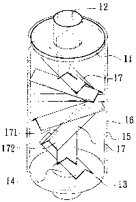
F1G. 1 is a perspective view of the present invention;
FIG. 2a is a side cross-sectional view of the present invention;
FIG. 2b is a top cross-sectional view of the present invention; and
FIG. 3 is an application view of the present invention.

CA 02467474 2004-05-17
3
DESCRIPTIt~N GF TFiE PREFERRED E11~~~JDIIi~ENT
Referring to FIG. 1 through FIG 2b, the muffler 1 o~f the present invention is
in
tube shape, an inner board 11 wifh a gas-in vube 12 is installed on one side
of the
muffler 1, a outer board 13 with at least one gas-out tube 14 is on the other
side of
the muffler 1, an external hood 15 covers the inner and outer boards 11, 13
vertically to form a chamber 1 C.
The major characteristic of the present invention is to have a plurality arrow
shape bars 17 installed horizontally along two spiral lines inside the chamber
16;
since the arrow shape bars 17 are installed along two spiral lines, therefore
the
arrangement looks like ladder, two adjacent arrow shape bars 17 are installed
with
special angle without vacant space, as shown in F1G. 2b. The tips 171 of the
arrow
shape bars 17 face the gas-in tube, one of the side wings 172 forms an
included
angle with the tip is around 25° to 45°, the best angle is
38°9 the length of the
arrow shape bars is from 25mm to 5gmm, the best length is 38mm; the thickness
of the side wings 172 is from l.flOmrn to 2.dOri~m, the best thickness is
1.25mm;
however in real application, these are not limited, the thickness of the side
wings
172 vibrate along with the gas flow and form self-interference condition to
lower
the noise.
In real application, as shown in FIG. 3, when the high pressure, high
temperature exhaust gas by engine enters the chamber 15 from the gas-in tube
12,
the exhaust gas is divided and dispersed by the arrow shape bars 17 and forms
disturbance condition, the exhaust gas is divided and dispersed by the spiral
shape arranged arrow shape bars 17 to have the gas collides to lower the noise
level; the installation of the arrow shape bars 17 increases the contact time
and
area with gas that lowers the temperature and pressure effectively, the
disturbance
condition also lowers the noise level effectively.
The application of the present invention not only reduces the resonance
condition as the partition design but also improves thr: poor noise
absorbability of

CA 02467474 2004-05-17
4
the noise reduction cotton, and makes the engine power output smoothly,
achieves
gasoline saving and longer engine life effect. 'I-he length and thickness of
the
arrow shape bars of present invention are adjustable to meet different
requirement
of different engines.
llVhile a preferred embodiment of the invention has been shown and
described in detail, it will be readily understood and appreciated that
numerous
omissions, changes and additions may be made without departing from the spirit
and scope of the invention.

Representative Drawing
A single figure which represents the drawing illustrating the invention.
Administrative Status

2024-08-01:As part of the Next Generation Patents (NGP) transition, the Canadian Patents Database (CPD) now contains a more detailed Event History, which replicates the Event Log of our new back-office solution.

Please note that "Inactive:" events refers to events no longer in use in our new back-office solution.

For a clearer understanding of the status of the application/patent presented on this page, the site Disclaimer , as well as the definitions for Patent , Event History , Maintenance Fee  and Payment History  should be consulted.

Event History

Description Date
Application Not Reinstated by Deadline 2008-05-20
Time Limit for Reversal Expired 2008-05-20
Deemed Abandoned - Failure to Respond to Maintenance Fee Notice 2007-05-17
Inactive: IPC from MCD 2006-03-12
Application Published (Open to Public Inspection) 2005-09-16
Inactive: Cover page published 2005-09-15
Inactive: First IPC assigned 2004-11-19
Application Received - Regular National 2004-06-18
Inactive: Filing certificate - No RFE (English) 2004-06-18

Abandonment History

Abandonment Date Reason Reinstatement Date
2007-05-17

Maintenance Fee

The last payment was received on 2006-03-16

Note : If the full payment has not been received on or before the date indicated, a further fee may be required which may be one of the following

  • the reinstatement fee;
  • the late payment fee; or
  • additional fee to reverse deemed expiry.

Patent fees are adjusted on the 1st of January every year. The amounts above are the current amounts if received by December 31 of the current year.
Please refer to the CIPO Patent Fees web page to see all current fee amounts.

Fee History

Fee Type Anniversary Year Due Date Paid Date
Application fee - small 2004-05-17
MF (application, 2nd anniv.) - small 02 2006-05-17 2006-03-16
Owners on Record

Note: Records showing the ownership history in alphabetical order.

Current Owners on Record
HUI-FANG CHEN
Past Owners on Record
None
Past Owners that do not appear in the "Owners on Record" listing will appear in other documentation within the application.
Documents

To view selected files, please enter reCAPTCHA code :


To view images, click a link in the Document Description column. To download the documents, select one or more checkboxes in the first column and then click the "Download Selected in PDF format (Zip Archive)" or the "Download Selected as Single PDF" button.

List of published and non-published patent-specific documents on the CPD .

If you have any difficulty accessing content, you can call the Client Service Centre at 1-866-997-1936 or send them an e-mail at CIPO Client Service Centre.


Document
Description 
Date
(yyyy-mm-dd) 
Number of pages   Size of Image (KB) 
Description 2004-05-16 4 243
Abstract 2004-05-16 1 39
Claims 2004-05-16 1 79
Drawings 2004-05-16 3 124
Representative drawing 2005-08-18 1 19
Filing Certificate (English) 2004-06-17 1 158
Reminder of maintenance fee due 2006-01-17 1 110
Courtesy - Abandonment Letter (Maintenance Fee) 2007-07-11 1 174
Fees 2006-03-15 1 26