Note: Descriptions are shown in the official language in which they were submitted.
CA 02467584 2004-05-18
WO 03/045619 PCT/CA02/01763
PRODUCT AND METHOD FOR LOW TEMPERATURE FLUXLESS BRAZING
CROSS REFERENCE TO RELATED APPLICATION
[0001 This is a continuation-in-part of U.S. Patent Application No.
09/990,507,
filed November 21, 2001, now pending , incorporated herein by reference.
FIELD OF THE INVENTION
[0002 The invention disclosed herein relates to a methods of fluxless brazing
of
aluminum at low temperature (about 730-1130°F or 388-610°C), and
to a family of
brazing alloy compositions with suitably low melting temperature ranges. 1n
particular,
the present invention relates to methods and compositions which are
particularly suited
for use in the brazing of two or more aluminum parts together or in the
joining of
dissimilar metals or combinations thereof, using aluminum or zinc based fitter
metals.
BACKGROUND OF THE INVENTION
(0003] Aluminum brazing is usually accomplished by heating with a torch or
other
localized heat source, by salt-dip brazing, or in a furnace, Furnace brazing
can be
performed in air using active flux salfis such as zinc chloride, however
preferred furnace
brazing processes use protective atmospheres such as vacuum, or inert gas, in
combination with either fluxless braze promoters, or non-corrosive fluxes.
Sometimes
furnace brazing is used to assemble one set of components, and then additional
components are brazed afterwards, using a secondary brazing operation that may
use a
localized heating method to avoid damage to the first brazed assembly. To
braze
aluminum, filler metals are normally used in the form of either (1 ) wire or
shim stock, (2)
a paste of flux and filler metal powder or as (3) a clad layer on brazing
sheet composite.
_1_
SUBSTITUTE SHEET (RULE 26)
CA 02467584 2004-05-18
WO 03/045619 PCT/CA02/01763
(0004] Processes for brazing usually provide at least one mating surface
having a
specific bonding material, placing the mating surfaces in contact, and then
applying a
particular heating procedure to bring the assembly to a temperature range
suitable to
accomplish melting of the filler metals, and upon cooling, joining of the
assembled
components. Either a flux or a braze promoter is provided, typically in the
filler metal, or
applied to the filler metal surface, to permit disruption of surface oxides,
and wetting of
the members to be joined by the filler metal.
(0005] Various methods of bonding aluminum are known in the prior art. In the
case of complex assemblies such as heat exchangers, where multiple, thin wall
aluminum components are required to be sealingly joined with multiple braze
bonds,
furnace brazing processes have been most widely used. Because of the
difficulty of
post-braze removal of corrosive fluxes or salts, two general categories of
furnace .
brazing have been most widely commercialized, ie, fluxless vacuum brazing
(VB), and
controlled atmosphere brazing (CAB) flux brazing.
(0006] In vacuum brazing, the parts to be brazed are provided with sufficient
quantities of magnesium, normally as mg alloy constituents in the filler metal
or in the
aluminum components, such that, when brought to temperature in a brazing
furnace
under sufficient vacuum conditions, the magnesium becomes sufficiently
volatile to
disrupt the oxide layer present and permit the underlying aluminum filler
metal to flow
together. While this technique provides for good bonding, it is essentially a
discontinuous process, resultant from the need to apply a vacuum, and thus, is
relatively
expensive. It is also difficult to control, as it is very sensitive to
oxidizing conditions in
the furnace atmosphere, and demands that onerous standards of material
cleanliness
be maintained. Further, the evaporation of the magnesium leads to condensation
in the
brazing furnace, which requires frequent removal, thereby further adding to
costs. For
heat exchanger applications, it is sometimes desirable to add small amounts of
zinc to
the aluminum materials being brazed, to improve corrosion resistance. A
limitation of VB
-2-
SUBSTITUTE SHEET (RULE 26)
CA 02467584 2004-05-18
WO 03/045619 PCT/CA02/01763
however, is that the zinc constituents are, like mg, relatively volatile, so
that control of
the as-brazed zinc composition in the aluminum structure being brazed, is
difficult.
[0007 In controlled atmosphere brazing (cab), the ability to braze does not
result from mechanical disruption of the oxide but rather, from chemical
modification of
the oxide by a fluoride salt flux which is applied to the parts. An example of
the type of
flux used for cab brazing is NOCOL014 T"" flux. As the name suggests, cab
brazing
does not require that a vacuum be drawn, such that the process may readily be
carried
out on a continuous basis, most typically using an inert gas furnace. While
this provides
for some reduction in cost, this cost saving is partially offset by the
necessity for
integration of flux application systems, many of which will suffer from
variable flux
loading. Moreover, after the flux has been applied, the flux can be
susceptible to flaking,
such that braze quality is affected, or contamination of the article of
manufacture can
occur. The flux can also be difficult to apply, especially on internal joints;
and can cause
problems in terms of furnace corrosion and cleanliness in the finished
product. More
importantly however, it has been found that the flux can lose activity when
exposed to
magnesium. Thus, this process is not suitable for brazing magnesium-enriched
aluminum alloys. As magnesium is a commonly used alloying element in aluminum
to
improve, inter alia, strength, this reduces the attractiveness of cab brazing.
[0008] Applications for brazing aluminum are not limited to heat exchangers,
however heat exchangers require relatively complex assemblies of stacked
plates or
tubular members that require reliable, low cost joining of multiple joints.
Some heat
exchangers, for example oil coolers and air conditioning evaporators, require
extensive
internal joints that must be brazed, in concert with internal passageways that
do not
provide a source for particulate flux residues in the functional lubrication
or refrigerant
system. Recently, stacked assemblies of brazed metal plates are being
considered as
possible methods of assembly of.fuel cell engines. Because of their structural
similarity
to plate-type heat exchangers, heat exchanger brazing technology is of
significant
-3-
SUBSTITUTE SHEET (RULE 26)
CA 02467584 2004-05-18
WO 03/045619 PCT/CA02/01763
interest. The joining of fuel cell plates requires reliable laminar type bonds
(extended
lap joints). However, fuel cell plates tend to be thin and have intricately
formed, narrow
flow field channels that are easily clogged by flux or by excess filler metal
flow. Using
prior art CAB processes, it has been difficult to satisfactorily braze fuel
cell plates
without internal flux contamination, and therefore CAB is unattractive, and
the cost of
vacuum brazing is prohibitive. As a consequence, fluxless brazing methods are
of
increased recent interest, for both heat exchanger and fuel cell engine
applications.
[0009] A number of brazing processes disclosed in the prior art disclose
utilize
filler metal compositions based on aluminum, zinc and silicon. For example,
U.S. Patent
No. 5,464,146 discloses the deposition of a thin film of aluminum eutectic
forming
material (Si, AI-Si or AI-Zn), by electron beam physical vapor deposition or
conventional
sputtering on at least one of the shapes to be brazed or joined. The assembly
is then
heated to a temperature between 1075 and 1105°F in the presence of a
suitable fluxing
agent, to diffuse eutectic forming material into the aluminum and form a braze
joint.
[00010] U.S. Patent No. 5,072,789, describes an aluminum heat exchanger with
an
aluminum fin and tube joined primarily by a fillet of zinc prepared using a
zinc chloride
slurry or zinc wire sprayed coating, again in the presence of a suitable flux.
U.s: pat. No.
4,901,908 describes a process of forming a zinc or zinc-aluminum alloy on an
aluminum
surface by a spraying technique, which alloy has a melting point lower than
that of the
core. In u.s. pat. No. 4,890,784, diffusion bonding of aluminum alloys is
performed
using a thin alloy interlayer of magnesium, copper or zinc placed between
mating
surfaces of the alloy members to be bonded.
[00011] U.S. Patent No. 4,785,092 discloses an aluminum clad brazing material
consisting of 4.5 to 13.5% Si, 0.005 to less than 0.1 % Sr, and additionally
one element
from the group consisting of 0.3 to 3.0% magnesium, 2.3 to 4.7% copper, and
9.3 to
10.7% zinc with the balance being aluminum. This alloy is useful for brazing
in vacuum
or inert atmospheres from 1040 to 1112°F.
-4-
SUBSTITUTE SHEET (RULE 26)
CA 02467584 2004-05-18
WO 03/045619 PCT/CA02/01763
[00012] U.S. Patent No. 3,703,763 describes forming a zinc bonding material
using
molten zinc to bond foamed aluminum with sheet aluminum.
(00013] In U.S. Patent No. 5,422,191, an aluminum brazing alloy is described
which can be used in either vacuum brazing or CAB brazing processes. The
brazing
alloy is clad with an aluminum alloy containing about 0.01 to 0.30% by weight
lithium
and 4 to 18% by weight silicon.
(00014] U.S. Patent Nos. 5,232,788, and 5,100,048, describe an aluminum
brazing
method using silicon metal powder with a brazing flux such as potassium
fluoroaluminate. The preferred metal component of the coating mixture is
silicon, but
other metals such as zinc, copper or nickel may be used.
(00015] A process for joining aluminum is described in U.S. Patent No.
5,044,546
for putting zinc on aluminum using a zinc immersion bath followed by cadmium
plating
and then heating in a vacuum to form a braze joint.
[00016] Another vacuum brazing process is found in U.S. Patent No. 5,069,980
using two clad alloys comprising silicon and a small amount of magnesium.
Other
elements in the cladding may be at least one of the following from a group
consisting of
Pb, Sn, Ni, Cu, Vin, Be, Li, and Ge.
(00017] Another method of joining aluminum members is described in U.S. Patent
No. 5,316,206 where aluminum is coated with zinc or a 5% aluminum-zinc alloy
by
dipping into the molten alloy bath. Following preassembly and applying a flux
material,
the aluminum members were heated to an elevated temperature in a furnace to
form
braze joints.
(00018] In a prior art method of fluxless aluminum brazing, the aluminum parts
being joined required plating with a braze-promoting layer typically
comprising nickel
andlor cobalt. The braze-promoting layer was applied by a variety of methods,
including
-5-
SUBSTITUTE SHEET (RULE 26)
CA 02467584 2004-05-18
WO 03/045619 PCT/CA02/01763
plating in alkaline plating media, conventional electroless deposition from a
hypophosphite solution. Alternatively, U.S. Patent Nos. 3,970,237, 4,028,200,
3,553,825 and 3,482,305 describe plating baths for electroless and
electrolytic plating of
bond-promoting metals such as nickel, nickel-lead, cobalt, cobalt-lead or
cobalt-nickel-
lead onto aluminum alloy surfaces.
[00019] Presently there are several known fluxless brazing methods, as
described
in U.S. Patent Nos. 3,332,517, 3,321,828 and many of the patents discussed
above,
which can be applied to brazing of aluminum alloys having a liquidus
temperature
somewhat above that of the presently available commercial AI-Si based filler
metals (ie
sufficiently above 1070 to 1175°F). Unfortunately, many aluminum
casting alloys
including die castings, and some high strength heat treatable (2xxx~or 7xxx)
alloys have
a liquidus and solidus temperature range below or very similar to those of the
commercial brazing alloys; and therefore are not suitable for the present
brazing
processes. Also, as discussed, some of the prior art brazing methods are
sensitive to
Mg concentrations above threshold amounts, which may limit their applicability
to
brazing 5xxx or some 6xxx aluminum materials.
[00020] Therefore, there is a continued need for brazing processes and brazing
products which are useful for brazing at low temperature in the absence of a
flux.
SUMMARY OF THE INVENTION
[00021] In one aspect, the present invention provides a brazing product for
low
temperature, fluxless brazing, comprising: (a) a temperature modifier layer
comprised
of at least 50% of a metal selected from.the group comprising zinc, aluminum
and
copper; and (b) a braze promoting layer comprising one or more metals selected
from
the group comprising nickel and cobalt; wherein, during brazing, the
temperature
modifier layer and the braze-promoting layer form a filler metal having a
liquidus
temperature in the range from about 730 to 1130°f.
-6-
SUBSTITUTE SHEET (RULE 26)
CA 02467584 2004-05-18
WO 03/045619 PCT/CA02/01763
[00022] In another aspect, the present invention provides a brazing product
for low
temperature, fluxless brazing, comprising: (a) a temperature modifier layer
comprised of
at least 50% of a metal selected from the group comprising zinc, aluminum and
copper;
and (b) a braze promoting layer comprising one or more metals selected from
the group
comprising nickel, cobalt and iron; wherein, during brazing, the temperature
modifier
layer and the braze-promoting layer and perhaps the substrate interact to form
a filler.
BRIEF DESCRIPTION OF THE DRAWINGS
[00023] The invention is now described, by way of example only, with reference
to
the accompanying drawings, in which:
[00024] Figure 1 is a schematic illustration of a preferred brazing preform
according to the invention;
[00025] Figure 2 is a schematic illustration of a preferred brazing sheet
according
to the invention in which a temperature modifier layer is applied by hot
dipping, arc
spraying, thermal spraying, low temperature kinetic energy metallization or
HVLP (high
velocity low pressure) coating methods;
[00026] Figure 3 is a schematic illustration of a preferred brazing sheet
according
to the invention in which a temperature modifier layer is applied by roll
bonding;
[00027] Figure 4 is a schematic illustration of a preferred brazing sheet
according
to the invention in which a temperature modifier layer is applied by
electroplating; and
[00028] Figure 5 is a schematic illustration of a preferred brazing sheet
according
to the invention in which a temperature modifier layer is applied by CVD or
PVD.
7_
SUBSTITUTE SHEET (RULE 26)
CA 02467584 2004-05-18
WO 03/045619 PCT/CA02/01763
DETAILED DESCRIPTION OF PREFERRED EMBODIMENTS
(00029] The present invention provides new methods for fluxless brazing at low
temperature, and a family of brazing products for use with this method having
filler metal
compositions with lowered melting temperatures, which products exhibit
improved
wetting and brazing characteristics when joining components comprised of
similar' of
dissimilar metals.
(00030] Brazing at lower temperature than conventional brazing processes
provides a number of advantages. For example, lower temperature brazing can be
used
to enable improved secondary brazing processes, including secondary furnace
brazing,
which may be used to increase brazed product design flexibility. Reduced braze
temperatures can be further exploited to reduce gauge thickness of component
parts,
especially aluminum parts, since the degree of thermal diffusion and erosion
of the
component substrate by the liquid filler metal will be decreased. Lower
temperatures will
provide easier control of the brazing process and make the brazing process
more
versatile and more economical. Further, the addition of self fluxing alloying
metals such
as nickel and lead or bismuth, to a filler metal composition braze promoting
layer
improves the filler metal wetting and spreading properties, thus permitting
brazing under
less demanding inert atmosphere or vacuum conditions. Successful fluxless
brazing
has been obtained in all brazing tests without fail, with the temperature
range of the new
filler metals about 250°f lower than the generally accepted flow
temperatures of
commercial aluminum-silicon alloys and, as such, is a significant improvement
in
aluminum brazing technology.
(00031] The novel brazing products according to the invention comprise brazing
alloys which form a filler metal during brazing, the filler.metal having a
liquidus
temperature in the range of about 730 to 1130°F (388 to 610°C),
more preferably 750 to
1050°C (400 to 570°C), typically from about 790 to 1050°F
(420 to 570°C). Preferably,
the.brazing products according to the invention include one or more
temperature
_g_
SUBSTITUTE SHEET (RULE 26)
CA 02467584 2004-05-18
WO 03/045619 PCT/CA02/01763
modification layers, at least one of which is an aluminum-based layer (at
least 50 weight
percent aluminum), a zinc-based layer (at least 50 weight percent zinc), or a
copper-
based layer (at least 50 weight percent copper). The temperature modifier
layer
optionally combines with other layers in the brazing alloy to form a filler
metal having a
liquidus temperature in the range of about 730 to 1130°F. Preferably,
the filler metal
comprises one or more of zinc, aluminum, copper, silicon, magnesium, antimony
and
nickel in amounts such that the filler metal has a liquidus temperature in the
range of
about 730 to 1130°F. Even more preferably, the filler metal comprises
zinc, zinc-nickel,
zinc-antimony, zinc-aluminum, aluminum-zinc, aluminum-zinc-silicon, aluminum-
silicon-
magnesium, aluminum-zinc-silicon-magnesium, aluminum-silicon-copper-magnesium,
aluminum-silicon-zinc-copper, or aluminum-silicon-copper-magnesium having a
liquidus
temperature in the range of about 730 to 1130°F.
(00032 In combination with the temperature modifier layer, there may
preferably
be applied one or more additional layers selected from braze-promoting layers,
bonding
layers, barrier layers, and additional temperature modifier layers. The
locations and
compositions of these additional layers will be described in detail below.
(00033] . The brazing products according to the invention exhibit excellent
wetting
and brazing characteristics without the need for a flux, when joining two or
more
components comprised of similar or dissimilar metals. For example, the brazing
products according to the invention may be used to join components comprising
aluminum to other aluminum-based components or to components comprised of
dissimilar metals. For example, the invention permits fluxless brazing of
aluminum
castings, including die castings, and aluminum alloys which are not readily
brazeable by
conventional means, such as 2xxx, 5xxx, 6xxx or 7xxx-series alloys. Certain
aluminum
alloys, notably 2xxx, 6xxx and 7xxx-series alloys brazed according to this
invention can
be heat treated after brazing, to increase strength. aluminum (previously
considered to
be unbrazeable); copper and copper alloy substrates; and, with suitable
coatings,
-9-
SUBSTITUTE SHEET (RULE 26)
CA 02467584 2004-05-18
WO 03/045619 PCT/CA02/01763
dissimilar metal combinations, including those disclosed in the applicants' co-
pending
application filed November 21, 2002 entitled "Improvements in Fluxless
Brazing".
[00034] The brazing method according to the invention is suitable for
continuous,
inert gas furnace brazing, or for secondary-operation brazing using a
protective
shielding gas and any suitable heating source, and can be used to produce a
range of
industrial products, including aluminum heat exchangers or similar stacked
assemblies
such as metallic plates for fuel cell engines. It is anticipated that this
brazing method
and layered filler metal compositions, can also be used as wire or preform
filler metals
for shielded arc welding or brazing.
(00035] The brazing products according to the invention are exemplified by the
following structures: .
Braze Preform
[00036] Figure 1 comprises a schematic diagram illustrating the layers making
up a
preferred structure of a brazing preform 10 according to the invention.
Preform 10
comprises a central temperature modifier layer 12, optional bonding layers 14
on both
sides of the temperature modifier 12, and braze-promoting layers 16 on top of
the
bonding layers 14. The preform 10 is preferably in the form of a sheet, foil,
shim, wire or
rod which is interposed between two similar or dissimilar metal components to
form an
assembly. When the assembly is heated to a temperature in the range from about
730
to 1130°F for a sufficient period of time, the entire preform melts to
form a filler metal
which brazes the components together. Thus, the preform 10 is consumed during
the
brazing process. Although less preferred, it is possible to apply the bonding
layer 14
and braze-promoting layer 16 to only one side of the temperature modifier 12.
[00037] The temperature modifier layer 12 is either zinc-based, aluminum-based
or
copper-based and has a liquidus temperature of about 730 to 1130°F.
Most preferably,
the temperature modifier layer is comprised of zinc; zinc and nickel; zinc and
antimony
-10-
SUBSTITUTE SHEET (RULE 26)
CA 02467584 2004-05-18
WO 03/045619 PCT/CA02/01763
aluminum and zinc; aluminum, aluminum and silicon; zinc and silicon; aluminum,
silicon
and magnesium, or aluminum, zinc, silicon and magnesium, in relative amounts
such
that the temperature modifier layer having a liquidus temperature in the range
of about
730 to 1130°F. Most preferably, the temperature modifier layer 12 of
preform 10
comprises zinc, zinc-nickel, zinc-aluminum, aluminum-zinc, aluminum-zinc-
silicon,
aluminum-silicon-magnesium, or aluminum-zinc-silicon-magnesium having a
liquidus
temperature in the range of about 730 to 1130°F.
[00038] The temperature modifier layer may also include an optional melt
depressant such as magnesium or copper and may also include an optional braze
modifier selected from bismuth, lead, antimony, thallium, lithium and
strontium.
[00039] It is to be understood that a bonding layer 14 is optional and is
preferably
applied where the temperature modifier layer 12 is aluminum-based and/or where
it is
desired to electroplate a nickel-based braze-promoting layer 16 under acidic
conditions.
Where the temperature modifier layer is zinc-based, a bonding layer is
typically not
required. This being said, the bonding layer preferably has a composition as
described
in the applicants' co-pending application filed November 21, 2002 entitled
"Improvements in Fluxless Brazing", incorporated herein by reference in its
entirety, and
preferably comprises one or more metals selected from the group comprising
zinc, tin,
lead, bismuth, nickel, antimony, magnesium, lithium and thallium. For example,
the
bonding layer may preferably be comprised of pure or substantially pure zinc,
tin, lead or
bismuth, or may be primarily zinc, tin, lead or bismuth (e.g. at least 50
weight %). Minor
amounts of these or other elements may be present, as discussed in more detail
below.
Typically, such elements are present at less than 10%, more usually less than
5% by
weight, and possibly less than 1 %.
[00040] In some preferred embodiments, the bonding layer is comprised
primarily
of zinc or tin in combination with one or more braze modifier elements
selected from the
group comprising bismuth, lead, lithium and antimony. The total amount of the
braze
-11-
SUBSTITUTE SHEET (RULE 26)
CA 02467584 2004-05-18
WO 03/045619 PCT/CA02/01763
modifiers may be up to 50%, but preferably is less than 25%, e.g. in the range
1 to 25%.
As a practical matter, even impurity levels of braze modifiers such as lead
and bismuth
can be sufficient to have an positive effects on brazing, but the amounts of
these
elements are preferably controlled in continuous processes such that they are
no longer
considered impurities.
[00041 In some preferred embodiments of the invention, the bonding layer
comprises a very thin zincate or stannate pretreatment; thin electroless
nickel, bismuth,
lead, nickel-lead or nickel-bismuth pretreatment; or a combination of
zincate/stannate
bonding layer with a copper plated, or sequential copper/nickel plated barrier
coating, as
preconditioning steps for subsequent fast zinc electroplating. This
preconditioning
permits the use of acid zinc plating baths, which have practical and
environmental
advantages over traditional cyanide alkaline copper baths.
[00042 The thickness of the bonding layer is preferably up to about 0.5
microns,
more preferably up to about 0.3 microns, and most preferably in the range of
0.01 to
0.15 microns or 0.02 to 0.15 microns, with 0.03 microns being an example of a
particularly preferred thickness. The bonding layer may be applied to the
substrate by
immersion plating, with or without mechanical abrasion, using the plating bath
compositions described in the applicants' co-pending application filed
November 21,
2002 entitled "Improvements in Fluxless Brazing". Furthermore, it will be
appreciated
that the application of a bonding layer to the substrate is merely one'of a
number of
"pretreatments" which can be used to promote adhesion of the braze-promoting
layer
and the uriderlying substrate, and that it may be possible to replace-the
bonding layer
by, or use it in combination with, any of the alternate pretreatments
disclosed in the
applicants' co-pending application filed November21, 2002 entitled
"Improvements in
Fluxless Brazing".
[00043] Suitable braze-promoting layers 16 for use in preform 10 include those
described in the applicants' co-pending application filed November 21, 2002
entitled
-12-
SUBSTITUTE SHEET (RULE 26)
CA 02467584 2004-05-18
WO 03/045619 PCT/CA02/01763
"Improvements in Fluxless Brazing". For example, the braze-promoting layer
preferably
comprises, one or more metals selected from the group comprising nickel,
cobalt and
iron. More preferably, the braze-promoting layer is nickel-based, and may
preferably
comprise pure nickel or nickel in combination with one or more alloying
elements and/or
impurities selected from the group comprising cobalt, iron, lead, bismuth,
magnesium,
lithium, antimony and thallium. Preferred braze modifiers include bismuth,
lead,
antimony and thallium. Specific examples of nickel-based braze-promoting
layers are
nickel, nickel-bismuth, nickel-lead, nickel-cobalt, nickel-bismuth-cobalt,
nickel-lead-
cobalt, nickel-lead-bismuth, nickel-bismuth-antimony, etc.
[00044] In some preferred embodiment of a nickel-based braze-promoting layer,
lead or bismuth is present in an amount of up to about 10%, preferably up to
about 5%,
and more preferably up to about 3%, although lower amounts and even trace
amounts
of these elements may also have a beneficial effect. For example, amounts of
lead or
bismuth as low as up to about 1.0%, about 0.01 to 1.0%, or about 0.01 to 0.05%
may be
beneficial..
[00045] The braze-promoting layer may be applied by electroplating,
electroless
plating, roll bonding, thermal spraying, plasma spraying, chemical vapor
deposition
(CVD), physical vapor deposition (PVD) or other techniques for depositing
metal or
metal alloys from a gas or vapour phase, although some of these methods would
be
impractical or difficult to control. Electroplating using the conditions and
plating baths
disclosed in the applicants' co-pending application filed November 21, 2002
entitled
"Improvements in Fluxless Brazing" is the most preferred method for applying
the braze-
promoting layer 16 to preform 10.
[00046] For aluminum alloy material systems, the thickness of the braze-
promoting
layer is preferably up to about 2.0 microns, more preferably up to about 1.0
microns, and
even more preferably up to about 0.5 microns, and most preferably about 0.05
to 0.5
-13-
SUBSTITUTE SHEET (RULE 26)
CA 02467584 2004-05-18
WO 03/045619 PCT/CA02/01763
microns. A preferred minimum thickness of the braze-promoting layer
is,about~0.25 to
0.30 microns. For alternate filler metal systems, notably zinc or copper-based
systems,
increased maximum thickness levels for the braze promoter layers may be
tolerable.
[00047] The preform 10 may preferably include an additiorial temperature
modifier
layer (not shown), preferably a copper-based layer applied between the bonding
layer
14 and the braze-promoting layer 16.
Brazing Sheet with Temperature Modifier Layer Applied by Hot Diapingi Arc
Spraying,,
Thermal Spraying. Low Temperature Kinetic Eneray Metallization or HVLP (High
Velocity Low Pressured Coating Methods
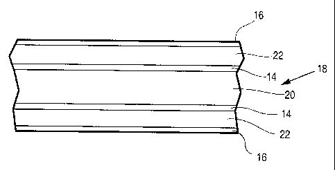
[00048] A preferred structure of this type of brazing sheet 18 is
schematically
illustrated in Figure 2, and comprises a central core layer 20, optional
bonding layers 14
on both sides of the core 20, temperature modifier layers 22 on top of the
bondirig
layers, and braze-promoting layers 16 on top of the temperature modifier
layers 22. The
brazing sheet is preferably incorporated into an assembly, either in the form
of a sheet
or a shaped object, and is brazed to one or more other components in the
assembly, the
other components either comprising similar or dissimilar metals. When the
assembly is
heated to a temperature in the range from about 730 to 1130°F for a
sufficient period of
time, the bonding layers 14, temperature modifier layer 22 and the braze-
promoting
layers 16 melt and are incorporated into the filler metal which brazes the
components
together. Although less preferred; it is possible to apply a bonding layer 14,
temperature
modifier layer 22 and braze-promoting layer 16 to only one side of the core
layer 20.
[00049] The bonding layers 14 and braze-promoting layers 16 preferably have
the
compositions described above. Furthermore, it is to be understood that the
bonding
layers 14 are optional and the most preferred bonding layers 14 are those
described
above which are zinc-based or nickel-based. The temperature modifier layer may
-14-
SUBSTITUTE SHEET (RULE 26)
CA 02467584 2004-05-18
WO 03/045619 PCT/CA02/01763
preferably have a composition as described above in the context of temperature
modifier
layer 12 of preform 10. .
(00050] . The core layer has a melting point high enough that it does not melt
during
the brazing operation, and is preferably formed from aluminum or an aluminum
alloy. In
some preferred embodiments the core sheet also comprises magnesium to increase
amongst others the strength of the core layer. The core may preferably contain
magnesium in a range of up to about 8%, more preferably in a range of up to
about
5.0%, and even more preferably up to about 2.0%. The amount of magnesium in
the
alloy is highly variable, depending on the intended application of the brazing
product,
and may be at or below 0.05% for AA3003 alloy.
[00051] Further alloying elements may be added to the core such as, but not
limited to, Cu, Zn, Bi, V, Fe, Zr, Ag, Si, Ni, Co, Pb, Ti, Zr and Mn in
suitable ranges.
[00052] Preferred aluminum alloys for use in the core layer include
conventional
aluminum alloys employed in, brazing such as AA3000-series alloys.
Alternatively, the
core materials may instead comprise other, less conventional, alloys such as
AA2000,
AA5000, AA6000, AA7000 and AA8000-series alloys, due to the fact that the
present
invention permits brazing at relatively low temperatures; and that diffusion
migration of
potentially deleterious elements from these higher alloyed core materials into
the braze
filler metal system, can be mitigated by a combination of lower braze
temperatures, and
the use of suitable barrier layers, or interlayers.
[00053] Rather than being formed from aluminum or an aluminum alloy, the core
may instead comprise titanium, titanium alloys, copper, bronze or brass or
other copper
alloys, high strength steel, low carbon steel, stainless steel, nickel or
nickel alloy steel,
or coated versions of these, and including the materials specifically
disclosed in the
applicants' co-pending application filed November 21, 2002 entitled
"Improvements in
Fluxless Brazing"
-15-
SUBSTITUTE SHEET (RULE 26)
CA 02467584 2004-05-18
WO 03/045619 PCT/CA02/01763
[00054], For typical heat exchanger applications, the core sheet Mas a
thickness
typically in a range of at most 5 mm, more preferably in the ranges of 0.1 to
2.5 mm, 0.1
to2.Ommor0.2to2mm.
(00055] Preferably, the brazing sheet according to this embodiment also
comprises
a thin, transient barrier coating (not shown) applied at the interface between
the core
layer 20 and the, bonding layer 14, or at the interface between the core layer
20 and the
temperature modifier layer 22 where the bonding layer 14 is not present. ~It
is believed
that the barrier coating acts to temporarily restrict diffusion of the low
melting filler
material (comprising layers 16, 22 and optionally 14) into the core layer 20
during
brazing, to avoid loss of eutectic-forming elements and to increase the
efficacy and
efficiency of the applied filler metal coating.
(00056] The barrier coating may preferably be the same as that of preform 10,
or
may be comprised of nickel, nickel-lead or nickel-bismuth and is applied to
the core
layer 20 or the bonding layer 14 prior to coating with the low-melting
temperature
modifier. Barrier coatings comprising copper, copper-lead or copper-bismuth
may also
be preferred in some embodiments, either in addition to, or in substitution
for, the nickel-
based barrier coating. The barrier coating can preferably be applied by
electroless or
electrolytic plating.
Brazing Sheet with Roll Bonded Cladding
[00057] Figure 3 illustrates a preferred structure of a brazing sheet 24
having a roll
bonded cladding layer 26 applied directly on the core layer 22 (which may have
been
produced by casting), the cladding layer 26 being comprised of a temperature
modifier.
A braze-promoting layer 16 as described above is applied on top of the
cladding layer
26. The brazing sheet 24 is preferably incorporated into an assembly, either
in the form
of a sheet or a shaped object, and is brazed to one or more other components
in the
assembly, the other components comprising either similar or dissimilar metals.
When
-16-
SUBSTITUTE SHEET (RULE 26)
CA 02467584 2004-05-18
WO 03/045619 PCT/CA02/01763
the assembly is heated to a temperature in the range of about 730 to
1130°F for a
sufficient period of time, the low-melting cladding layer 26 and the braze-
promoting layer
16 melt and are incorporated into the filler metal, thereby brazing the
components
together. Although less preferred, it is possible to apply cladding layer 26
and braze-
promoting layer 16 to only one side of the core layer 20.
[00058] The cladding layer comprises a temperature modifying metal or alloy,
preferably the same as the temperature modifier 12 of perForm 10, within the
limits of
rolling mill processibility.
(00059] The braze-promoting layer 16 is as described above with reference to
the
preform, and the core 20 is as described above with reference to the brazing
sheet
having a temperature modifier layer applied by hot dipping, etc.
[00060] In an alternate, related embodiment, the roll-bonded cladding layer 26
simply comprises an aluminum-silicon brazing alloy and a temperature modifier
layer
comprising zinc is applied on top of the cladding, typically by
electroplating. This
structure can be obtained merely by plating zinc onto commercially available
aluminum
brazing sheets which may have a 3~ocx-series core alloy and a 4~ocx-series
cladding
alloy.
Core Sheet with Electroplated Temperature Modifier La rLer
(00061] A preferred structure of this type of brazing sheet 28 is
schematically
illustrated in Figure 4, and is similar to the structure shown in Figure 2.
The brazing
sheet 28 may preferably comprise a central core layer 20, optional bonding
layers 14 on
both sides of the core 20, electroplated temperature modifier layers 30 on top
of the
bonding layers 14, and braze-promoting~layers 16 on top of the bonding layers
14. The
brazing sheet 28 is preferably incorporated into an assembly, either in the
form of a
sheet or a shaped object, and is brazed to one or more other components in the
assembly, the other components either comprising similar or dissimilar metals.
When
-17-
SUBSTITUTE SHEET (RULE 26)
CA 02467584 2004-05-18
WO 03/045619 PCT/CA02/01763
the assembly is heated to a temperature in the range from about 730 to
1130°F for a
sufficient period of time, the bonding layers 14, temperature modifier layer
30 and the
braze-promoting layers 16 melt,,and the contacted surfaces of the core or
interlayer
materials and are incorporated into the filler metal which brazes the
components
together. Although less preferred, it is possible to apply a bonding layer 14,
temperature
modifier layer 30 and braze-promoting layer 16 to only one side of the core
layer 20.
(00062] The bonding layers 14 and braze-promoting layers 16 preferably have
the
compositions described above, and it is to be appreciated that the bonding
layers 14 are
optional. Where a bonding layer is present, it preferably comprises a very
thin zincate or
stannate pretreatment, or a thin electroless nickel, nickel-lead or nickel-
bismuth
pretreatment, as a pretreatment for subsequent fast zinc electroplating.
Electroplating
solutions utilized in the plating of the braze promoting layers include
solutions of nickel
sulfate, nickel chloride, sodium citrate, sodium gluconate, sodium acetate,
ammonium
chloride, ammonium sulfate, ammonium hydroxide and lead acetate as described
in
U.S. Patent No. 4,028,200 and as described in the applicants' co-pending
application
entitled "Improvements in Fluxless Brazing", filed on November 21, 2002.
(00063 The temperature modifier layer 30 is either zinc-based, aluminum-based
or
copper-based and has a liquidus temperature of about 730 to 1130°F.
Most preferably,
the temperature modifier layer 30 is comprised of zinc; zinc and nickel;
aluminum and
zinc; aluminum, zinc and silicon; aluminum, silicon and magnesium, or
aluminum, zinc,
silicon and magnesium, in relative amounts such that the temperature modifier
layer has
a liquidus temperature in the range of about 730 to 1130°F. Most
preferably, the
temperature modifier layer 30 of brazing sheet 28 comprises zinc, zinc-nickel,
zinc-
aluminum, aluminum-zinc, aluminum-zinc-silicon, aluminum-silicon-magnesium, or
aluminum-zinc-silicon-magnesium having a liquidus temperature in the range of
about
730 to 1130°F, eg clad brazing sheet with an aluminum-silicon cladding,
the filler metal
being deposited on the aluminum-silicon eutectic.
-18-
SUBSTITUTE SHEET (RULE 26)
CA 02467584 2004-05-18
WO 03/045619 PCT/CA02/01763
[00064] The core layer has a melting point high enough that it does not melt
during
the brazing operation, and has a composition as described above with reference
to core
layer 20 of brazing sheet 18 shown in Figure 2. Most preferably, the core
layer 20 of
brazing sheet 28 formed from aluminum or an aluminum alloy.
[00065] As in the brazing sheet 18 shown in Figure 2, the brazing sheet 28 may
also be provided with a thin, transient barrier coating (not shown) applied at
the interface
between the core layer 20 and the bonding layer 14, or at the interface
between the core
layer 20 and the temperature modifier layer 30 where the bonding layer 14 is
not
present.
[00066] The barrier coating is preferably comprised of nickel, nickel-lead or
nickel-
bismuth and is applied to the core layer 20 or the bonding layer 14 prior to
coating with
the low-melfing temperature modifier. Barrier coatings comprising copper,
copper-lead
or copper-bismuth may also be preferred in some embodiments, either in
addition to, or
in substitution for, the nickel-based barrier coating. The barrier coating can
preferably
be applied by electroless or electrolytic plating.
[00067] It may also be preferred in this embodiment to provide a copper-based,
preferably copper or copper-tin, layer either directly under or on top of the
braze-
promoting layer 16. In this case, copper likely behaves more like a
temperature modifier
than a barrier layer, except perhaps with respect to the facing surface of
another
contacting member to be brazed.
Brazing Sheet with Temperature Modifier Layer Applied by CVD or PVD
[00068] The preferred structure of this type of brazing sheet 32 is
schematically
illustrated in Figure 5, and comprises a central core layer 20, optional
bonding layers 14
on both sides of the core 20, CVD or PVD-deposited temperature modifier layers
34 on
top of the bonding layers 14, and braze-promoting layers 16 on top of the
temperature
modifier layers 34. The brazing sheet is preferably incorporated into an
assembly, either
-19-
SUBSTITUTE SHEET (RULE 26)
CA 02467584 2004-05-18
WO 03/045619 PCT/CA02/01763
in the form of a sheet or a shaped object, and is brazed to one or more other
components in the assembly, the other components either comprising similar or
dissimilar metals. When the assembly is heated to a temperature in the range
from
about 730 to 1130°F for a sufficient period of time, the bonding layers
14, temperature
modifier layer 34 and the braze-promoting layers 16 melt and are incorporated
into the
filler metal which brazes the components together. Although less preferred, it
is
possible to apply a bonding layer 14, temperature modifier layer 34 and braze-
promoting
layer 16 to only one side of the core layer 20.
[00069 The bonding layers 14 and braze-promoting layers 16 preferably have the
compositions described above. Furthermore, it is to be understood that the
bonding
layers 14 are optional and the most preferred bonding layers 14 are those
described
above which are zinc-based or nickel-based. The temperature modifier layer may
preferably have a composition as described above in the context of temperature
modifier
layer 12 of preform 10.
(00070 The core layer has a melting point high enough that it does not melt
during
the brazing operation, and has a composition as described above with reference
to core
layer 20 of brazing sheet 18 shown in Figure 2. Most preferably, the core
layer 20 of
brazing sheet 28 formed from aluminum or an aluminum alloy.
[00071 ~ As with brazing sheets 18 and 28 described above, the brazing sheet
32
according to this embodiment may also be provided with a thin, transient
barrier coating
(not shown) applied at the interface between the core layer 20 and the bonding
layer 14,
or at the interface between the core layer 20 and the temperature modifier
layer 34
where the bonding layer 14 is not present.
[00072 The barrier coating is preferably comprised of nickel, nickel-lead or
nickel-
bismuth and is applied to the core layer 20 or the bonding layer 14 prior to
coating with
the low-melting temperature modifier. Barrier coatings comprising copper,
copper-lead
-20-
SUBSTITUTE SHEET (RULE 26)
CA 02467584 2004-05-18
WO 03/045619 PCT/CA02/01763
or copper-bismuth may also be preferred in some embodiments, either in
addition to, or
in substitution for, the nickel-based barrier coating. The barrier coating can
preferably
be applied by electroless or electrolytic plating.
Powder Metal Compositions
[00073] A further embodiment of the invention exploits the use of powder metal
compositions including zinc, aluminum, silicon, nickel and braze modifiers,
for example
the compositions may include zinc, zinc-aluminum, zinc-silicon, zinc-aluminum-
silicon in
combination with nickel powders, with or without braze modifiers as described
above.
Preferably the nickel and braze modifier are added together as nickel-lead or
nickel-
bismuth powders.
(00074] The powder metal mixtures can be applied to an aluminum-containing
substrate as a coating, using a suitable binder, by roll compaction into the
substrate
surface,'or as a perform, to form selective or continuous, brazeable coatings.
The
substrate may comprise aluminum or an aluminum alloy, and may comprise a
brazing
sheet with an aluminum-silicon cladding. In terms of binders, after exhaustive
tests of
binders normally used for brazing pastes, including those used for CAB
brazing, all of
which tend to leave black residues on brazing, or degraded brazing, the
inventors have
found that particularly effective binders are polymeric binders, preferably
propylene
carbonate binders, and even more preferably such polymers in the form of
aqueous
emulsions. One preferred binder is QPAC-40T"" from PAC Polymers.
(00075] In one specific example, a mixture prepared from a slurry of 90 mg
zinc
powder, 10 mg nickel powder, 160 mg water, and 40 mg of QPAC emulsion, was
successfully brazed with 3003 aluminum.
(00076] In the powder coating or roll compaction embodiment, the substrate
surface may preferably be pre-conditioned by suitable cleaning pretreatment,
or by
application of a bonding layer, for example by a zincate or stannate
treatment, or by
SUBSTITUTE SHEET (RULE 26)
CA 02467584 2004-05-18
WO 03/045619 PCT/CA02/01763
application of a thin pre-coating comprised of nickel, bismuth, lead, nickel-
lead, nickel-
b~smuth, zinc-bismuth, zinc-lead, tin. bismuth or tin-lead. For roll
compaction application
of powder coatings, to high strength alloys such as 2024 aluminum, it may be
preferred
to use an aluminum clad version of the alloy, ie where the 2024 material is
clad with a
surface layer of soft, nearly pure aluminum.
[00077] An important point in all of these embodiments is that in addition to
the
objective of achieving a desired low melting filler metal system for the
purpose of joining,
there is generally inherent dissolution, and alloying together with the filler
metal, of the
surface layers of the substrate material. Accordingly, by appropriate
selection of the filler
metal system, it will be appreciated that it may be possible to deliberately
adjust the
surface alloy composition of the as-brazed material. For example, deliberate
use of zinc
filler metal systems may be used to enrich the surfaces of an aluminum-brazed
product
with zinc, for the purposes of sacrificial corrosion protection, or to achieve
surface
hardening characteristics.
EXAMPLES AND TABLES
EXAMPLE 1
(00078] Table 1 indicates how various combinations of braze filler metal can
reduce melting temperatures as aluminum concentrations decrease and zinc
concentrations increase, with a sharp temperature decrease occurring at the
eutectic at
4% aluminum - 96% zinc.
-22-
SUBSTITUTE SHEET (RULE 26)
CA 02467584 2004-05-18
WO 03/045619 PCT/CA02/01763
Table 1
A1 (%) Zn (%) Si (%) Pb (%) Ta (%) Bi (%) F.
0.0 100.0 - - - - 786
4.0 96.0 - - - - 720
3.5 95.0 - 1.5 - - 752
13.0 85.3 1.2 - 0.5 - 800
20.5 76.0 2.0 - - 1.5 850
29.0 66.0 3Ø 2.0 - - 885
38.2 57.0 4.8 - - - 910
46.5 47.5 6.0 - - - 950
54.8 38.0 7.2 - - - 985
63.1 28.5 8.4 - - - 1015
88.2 ~ = I 11.8 - I - ~ - 1100
I
[00079] The alloys shown in Table 1 were prepared experimentally by casting,
rolled into sheet, and then used to determine a successful melting range and
also
wetting and spreading characteristics. These experiments showed that the
introduction
of an increasing percentage of zinc to the traditional eutectic aluminum-
silicon filler alloy,
reduced the melting temperature of the new brazing alloy. The wetting and
spreading .
tests also proved that the zinc-aluminum-silicon systems according to the
invention yield
alloys feasible for the fluxless brazing of die castings and other components
in the
neighborhood of 730 to 1130°F, more preferably 750 to 1050°F, as
compared to 1080 to
1175°F for the presently used commercial aluminum-silicon filler
metals.
[00080] In addition to the aforementioned alloying elements, the brazing
composition of the alloys shown in the table may include minor elements and
impurities
amounts of up to 1.0% iron, 0.25% titanium, 0.25% manganese, 0:2% copper, 0.3%
magnesium, etc.
EXAMPLE 2
- 23 -
SUBSTITUTE SHEET (RULE 26)
CA 02467584 2004-05-18
WO 03/045619 PCT/CA02/01763
(00081] Several tensile strength measurements were made with brazed lap
specimens, using zinc alone and zinc with nickel-lead plated zinc as filler
materials
(table 2) to bond type 3003 aluminum to 3003 alui~ninum.
(00082] With respect to the various tests, nos. 1 through 5 uses aluminum type
3003 and zinc foil that is 0.38 mm. thick and nos. 6 through 11 utilize zinc
foil which is
0.10 mm. thick. The braze tests were run with type 3003 aluminum as a lap
joint with a
small sheet of zinc placed between the 3003 aluminum pieces. As shown in table
2, the
electroplated nickel-lead on zinc greatly improved the braze quality and
strength and
made it possible to lower the braze temperature to 900°F.
Table 2
No. her Zinc ThicknessBraze Braze Temp.Braze Tensile
Material~ Promoter F Quali Stren h b
1 Zinc 0.38 - 1120 Good 455
2 Zinc 0.38 Ni-Pb 950 Good 490
3 Zinc 0.38 - 950 Poor 90
4 Zinc 0.38 Ni-Pb 900 Good 548
S Zinc 0.38 - 900 Poor 80
6 Zinc 0.10 - 900 No Braze -
7 Zinc 0.10 Ni-Pb 900 Good 536
8 Zinc 0.10 - 950 No Braze -
9 Zinc 0.10 - 1000 No Braze -
Zinc 0.10 - 1050 No Braze -
11 Zinc 0.10 - 1100 Poor <100
EXAMPLE 3
(00083] A second group of tests were conducted as in Example 2 but with a
shorter lap joint in the order of 0.25 inches using 3003 aluminum specimens.
For all
tests, a small piece of zinc metal was placed between the aluminum specimens
and, as
shown in table 3, the braze temperature was lowered to 800°F when
nickel-lead was
electroplated on the zinc spacer.
-24-
SUBSTITUTE SHEET (RULE 26)
CA 02467584 2004-05-18
WO 03/045619 PCT/CA02/01763
Table 3
Filler Braze Braze Temp. Tensile
No. Material Promoter ~ Braze uali Stren h
b
1 Zinc Ni-Pb 850 Good 648
2 Zinc Ni-Pb 800 Good 580
3 Zinc - 1100 Poor 136
4 Zinc Ni-Pb 900 Good 516
S Zinc - 1000 No Braze -
EXAMPLE 4
[00084] In additional testing, small samples of zinc alloys were prepared in a
tube
furnace and in an arc-melting chamber. The alloys were then roll milled to
form thin
sheets and braze tests were run with the thin alloy sheet placed between a
3003
aluminum tube and plate. Results of these tests are shown in table 4 and show
some
variations in braze quality.
Table 4
Filleraterial Braze ThicknessBraze Braze
No. Allo M % Promoter mils Tem. ~uali
Zn Comp.
Al
Si
1 I 100 - - Ni-Pb 9 820 Excel.
2 I 100 - - - 9 900 Poor
3 VI 100 - - Ni-Pb 15 820 Good
4 III 90 8:8 1.2 Ni-Pb 10 1000 Good
V 90 8.8 1.2 Ni-Pb 14 1000 Excel.
6 V 90 8.8 1.2 Ni-Pb 14 900 Excel.
7 V 90 8.8 1.2 Ni-Pb 14 850 Good
[00085] With respect to the alloys listed in table 4, alloys I & III were arc
melted,
and alloys V & VI were cast in air and the center (non oxidized) section was
used. It
appears from the above cited results and from additional testing to be
disclosed that the
braze quality is good to excellent even with the zinc-aluminum-silicon alloy
if the nickel-
lead promoter is added.
- 25 -
SUBSTITUTE SHEET (RULE 26)
CA 02467584 2004-05-18
WO 03/045619 PCT/CA02/01763
[00086] - Further test results of zinc-aluminum-silicon-alloy braze joints are
listed in
table 5.
Table 5
Filler
Material
No bo % ThicknessBraze Braze Braze
Com
osition
. y Zn Al Si mils PromoterTemp. Quality
(~
1 VII 100 - - 5 Ni-Pb 900 Good
2 VII 100 - - 5 - 900 Poor
3 VIII 100 - - 5 . Ni-Pb 900 Good
4 IX 100 - 6 Ni-Pb 900 Good
S XI 98 2 - 5 Ni-Pb 900 Excellent
6 XI 98 2 - 5 - 900 No braze
7 VIII & 90 8.8 1.2 4 Ni-Pb 900 Good
XII
8 VIII & 90 8.8 1.2 7 Ni-Pb 900 Fair
XII
9 VIII & 90 8.8 1.2 7 - 900 No Braze
X1I
[00087] With respect to the alloys shown in column 2, alloy VII is zinc
received
from Alpha Co.; alloy VII I is Alpha Co. zinc melted in a nitrogen furnace at
900°F and roll
milled to a thin sheet; alloy IX is zinc wire from Tafa Co. melted in a
furnace with a
nitrogen atmosphere at 900°F followed by rolling to a thin sheet; alloy
XI is a metal strip
0.022 inches thick containing 98% zinc and 2% aluminum; and alloy XI I is a
cast alloy
consisting of 88% aluminum and 12% silicon, again roll milled into a thin
sheet.
EXAMPLE 5
[00088] Eraze tests were also conducted using a type 3003 aluminum tube on
aluminum sheet with pure zinc, 98 zinc - 2 aluri-iinum, and 90 zinc - 8.8
aluminum -1.2
silicon shim stock as a filler material. Good braze joints were obtained from
nickel-lead
plating the filler material, while a poor joint was obtained without the
nickel plate.
EXAMPLE 6
-26-
SUBSTITUTE SHEET (RULE 26)
CA 02467584 2004-05-18
WO 03/045619 PCT/CA02/01763
(00089 To determine whether any differences exist, between nickel plate on
zinc
and nickel-lead plate on zinc, another series of braze and tensile tests were
conducted
using aluminum alloys AA2024, 3003, 5052 and 7075. The aluminum thickness of
the
tensile bars was increased to 0.090 inch make the break more likely occur at
the braze
joint than in the aluminum price. A small section (0.75 x 0.20 x 0.045 inch)
was cut out
of the aluminum bar (2.0 x 0.75 x 0.090 inch) for placing the zinc between the
two
mating tensile bars. The samples were brazed at 800 or 825°f. As shown
in tables 6 -
13 the tensile strength increased in all tests when the zinc was electroplated
with nickel
and lead.
Table 6. Tensile Strength Measurements with Zinc and Aluminum 2024** Brazed at
g00°F
Tensile
Test No. ~u~num Metal PlatedBraze Strength Break
Cleaning on Quality Point***
~ Zinc ounds
24-1 Acetone - No braze - -
24-2 Acetone - No braze - -
24-3 Acetone Nickel Good 210 BJ
24-4 Acetone Nickel Good 288 BJ
24-S Acetone Ni-Pb Good 456 BJ
24-6 Acetone Ni-Pb Good 590 Al Allo
24-7 Caustic - Good 32 BJ
24-8 Caustic - Good 168 BJ
24-9 Caustic Nickel Good 568 BJ
~
24-10 Caustic Nickel Good 800+ A1 Allo
24-11 Caustic Ni-Pb Good 616 BJ
* Zinc Shim Stock Size (in) = 0.2 x 0.75 x 0.015
** Aluminum Specimen Size (in) = 2 x 0.75 x 0.09 with cut-out of 0.2 x 0.75 x
0.045
*** BJ-break occurred at the braze joint
Table 7. Tensile Strength Measurements with Zinc* and Aluminum 2024** Brazed
at
825°F
Aluminum Metal PlatedBraze Tensile Break
Test No. Cleaning on Quali Strength post***
Zinc ~' ounds
31-1 Acetone - No braze -
31-2 Acetone - No braze -
31-3 Acetone Nickel Good 280 BJ
31-4. Acetone Nickel Good 200 BJ
-27-
SUBSTITUTE SHEET (RULE 26)
CA 02467584 2004-05-18
WO 03/045619 PCT/CA02/01763
31-5 Acetone Ni-Pb Fair 570 A1 Allo
31-6 Acetone Ni-Pb Good 570 A1 Alloy
31-7 Caustic - Poor 80 BJ
31-8 Caustic - Poor 60 BJ
31-9 Caustic Nickel Good 350 BJ
31-10 Caustic Nickel Good 370 BJ
31-11 Caustic Ni-Pb Good 620 Al Alloy
31-12 Caustic Ni-Pb Good 660 A1 Allo
* Zinc Shim Stock Size (in) = 0.2 x 0.75 x 0.015
** Aluminum Specimen Size (in) = 2 x 0.75 x 0.09 with cut-out of 0.2 x 0.75 x
0.045
*** BJ-break oceurred at the braze joint
Table 8. Tensile Strength Measurements with Zinc* and Aluminum 3003** Brazed
at
800°F
Aluminum Metal PlatedBraze Tensile Break
Test No. on Strength
C leaning Quality Point***
Zinc ounds
25-1 Acetone - No braze - -
25-2 Acetone - No braze - -
25-3 Acetone Nickel Good 280 BJ
25-4. Acetone Nickel Good 40 BJ
25-5 Acetone Ni-Pb Good 445 A1 Alloy
25-6 Acetone Ni-Pb Good 430 A1 Allo
25-7 Caustic - Good 75 BJ
25-8 Caustic - Good 300 BJ
25-9 Caustic Nickel Good 370 BJ
25-10 Caustic Nickel Good 365 BJ
25-11 ~ Caustic Ni-Pb ( Good ~ 510 A1 Alloy
~
* Zinc Shirn Stock Size (in) = 0.2 x 0.75 x 0.015
** Aluminum Specimen Size (in) = 2 x 0.75 x 0.09 with cut-out of 0.2 x 0.75 x
0.045
*** BJ-break occurred at the braze joint
Table 9. Tensile Strength Measurements with Zinc* and Aluminum 3003** Brazed
at
825°F
Aluminum Metal PlatedBraze Tensile Break
Test No. on ~ Strength
Cleaning ~ Quali ounds Pest
Zinc
30-1 Acetone - No braze - -
30-2 Acetone - No braze - =
30-3 Acetone Nickel Good 430 BJ
30-4 Acetone Nickel Good 250 ~ BJ
30-5 Acetone Ni-Pb Good 460 A1 Alloy
30-6 ~ Acetone Ni-Pb ~ Good 470 A1 Alloy
~
_ 28 _
SUBSTITUTE SHEET (RULE 26)
CA 02467584 2004-05-18
WO 03/045619 PCT/CA02/01763
30-7 Caustic - No braze - -
_
30-8 Caustic - No braze - -
30-9 ~ Caustic Nickel Good 310 BJ
30-10 Caustic Nickel Good 150 BJ
30-l l Caustic Ni-Pb Good 480 A1 Alloy
j_ 30-12 ~ Caustic Ni-Pb
~ Good 470 A1 Alloy
_ * Zinc Shim Stock Size (in) = 0.2 x 0.75 x 0.015
** Aluminum Specimen Size (in) = 2 x 0.75 x 0.09 with cut-out of 0.2 x 0.75 x
0.045
*** BJ-break occurred at the braze joint
Table 10. Tensile Strength Measurements with Zinc* and Aluminum 5052** Brazed
at
800°F
Tensile
Test No. Aluminum Metal PlatedBraze S~.ength Break
Cleaning on Quality Point***
Zinc ounds
27-1 Acetone - Poor 55 BJ
27-2 Acetone - No braze - -
27-3 Acetone Nickel Good 385 BJ
27-4 Acetone Nickel Good 380 BJ
27-5 Acetone Ni-Pb Good 665 BJ
27-6 Acetone Ni-Pb Good 575 BJ
27-7 Caustic - Fair 90 BJ
27-8 Caustic - Fair 60 BJ
27-9 Caustic Nickel Good 420 BJ
27-10 Caustic Nickel ~ Good 210 BJ
27-11 ~ Caustic Ni-Pb Good 640 BJ
27-12 Caustic Ni-Pb Good 510 BJ
* Zinc Shim Stock Size (in) = 0.2 x 0.75 x 0.015
** Aluminum Specimen Size (in) = 2 x 0.75 x 0.09 with cut-out of 0.2 x 0.75 x
0.045
*** BJ-break occurred at the braze joint
Table 11. Tensile Strength Measurements with Zinc* and Aluminum 5052** Brazed
at
825°F
Aluminum Metal PlatedBraze Tensile Break
T on
t N
es Cleaning Zinc Quality strength point***
o.
ounds
32-1 Acetone - Good 110 BJ
32-2 Acetone - Good 80 BJ
32-3 Acetone Nickel Good 50 BJ
32-4 Acetone Nickel Good 180 BJ
32-5 Acetone Ni-Pb Good 800 BJ
-29-
SUBSTITUTE SHEET (RULE 26)
CA 02467584 2004-05-18
WO 03/045619 PCT/CA02/01763
32-6 Acetone Ni-Pb Good 630 BJ
32-7 Caustic - Good 240 _
BJ
32-8 Caustic ~ - No braze - -
32-9 Caustic Nickel
32-10 Caustic Nickel Good 360 BJ
32-11 Caustic ~ Ni-Pb Good 880 A1 Allo
32-12 ~ Caustic Ni-Pb Good 680 BJ
* Zinc Shim Stock Size (in) = 0.2 x 0.75 x 0.015
** Aluminum Specimen Size (in) = 2 x 0.75 x 0.09 with cut-out of 0.2 x 0.75 x
0.045
*** BJ-break occurred at the braze joint
Table 12. Tensile Strength Measurements with Zinc* and Aluminum 7075** Brazed
at
800°F
Tensfle
Test No. ~ununum Metal Plated. Braze Strength Break
Cleaning on Quality ounds p~t***
Zinc
34-1 Acetone - No braze - -
34-2 Acetone - No braze - -
34-3 Acetone Nickel Good 360 BJ
34-4. Acetone Nickel Good 40 BJ
34-5 Acetone Ni-Pb Good 680 BJ
34-6 Acetone Ni-Pb Good 680 BJ
34-7 Caustic - No braze - -
34-8 , Caustic - No braze - -
34-9 Caustic Nickel Good 390 BJ
34-10 Caustic Nickel Good 430 BJ
34-11 Caustic Ni-Pb Good 700 BJ
34-12 Caustic Ni-Pb Good 770 BJ
~
* Zinc Shim Stock Size (in) = 0.2 x 0.75 x 0.015
* * Aluminum Specimen Size (in) = 2 x 0.75 x 0.09 with cut-out of 0.2 x 0.75 x
0.045
*** BJ-break occurred at the braze joint
Table 13. Tensile Strength Measurements with Zinc* and Aluminum 7075** Brazed
at
825°F
Aluminum Metal Plated Braze Tensile Break
Te on
t N
s Cleaning Zinc Quality Strength point***
o.
ounds
33-1 Acetone - No braze - -
33-2 Acetone - Good 20 BJ
-30-
SUBSTITUTE SHEET (RULE 26)
CA 02467584 2004-05-18
WO 03/045619 PCT/CA02/01763
33-3 Acetone Nickel Good 20 BJ
33-4. Acetone Nickel Good 460 BJ
33-S Acetone Ni-Pb Good 610 A1 Alloy
33-6 Acetone Ni-Pb Good 600 A1 Allo
33-7 Caustic - Good 180 BJ
33-8 Caustic - Good 30 BJ
33-9 ~ Caustic Nickel Good 480 BJ
33-10 Caustic Nickel Good 650 BJ
33-11 Caustic Ni-Pb Good 715 Al Alloy
33-12 Caustic Ni-Pb Good 770 BJ
* Zinc Shim Stock Size (in) = 0.2 x 0.75 x 0.015
** Aluminum Specimen Size (in) = 2 x 0.75 x 0.09 with cut-out of 0.2 x 0.75 x
0.045
*** BJ-break occurred at the braze joint
EXAMPLE 7
[00090] Additional tests were performed on AA6061 and AA6262 aluminum
transmission oil cooler fittings for brazing to non-clad type 3003 aluminum ,
using zinc
filler metal. (Table 14). The zinc was plated with standard Long Manufacturing
nickel
plating solution and all samples were brazed at 800°F in a laboratory
furnace. The two
samples that were not nickel-plated did not braze well, indicating that nickel-
lead plating
on zinc was needed for an acceptable braze joint as shown in Table 14.
Table 14
Test No. Fitting Size F~er MaterialBraze PromoterBraze Quality
ODx>DxHT
1 1.22 x 0.43 x 0.43 Zinc Ni-Pb Good
3 1.22 x 0.50 x 1.58 Zinc Ni-Pb Excellent
1.22 x 0.43 x 0.43 Zinc - No Braze
6 1.30 x 0.57 x 0.72 Zinc Ni-Pb Excellent
7 1.30 x 0.57 x 0.72 Zinc - Fair
8 1.22 x 0.50 x 1.58 Zinc Ni-Pb Good
The zinc was in the form of a 0.38 mm. (0.15 inch) thick foil from BDH
Chemicals.
EXAMPLE 8
-31-
SUBSTITUTE SHEET (RULE 26)
CA 02467584 2004-05-18
WO 03/045619 PCT/CA02/01763
[00091 Also tested were two thermal spray techniques for applying metallic
coatings, flame spray and electric arc spray. The metals, (zinc and aluminum-
12%
silicon, in wire form) were vaporized or melted and atomized to form coatings
on
AA3003 aluminum using the electric-arc process in a nitrogen atmosphere. They
were
sprayed from a distance of 8 inches with the electric power controlled at
approximately
22 to 25 volts and 100+ amps. Braze tests were run using 3003 aluminum tubes
placed
on top of the thermal spray coated coupons. The best results were obtained
with
thermal sprayed zinc, or aluminum-12% silicon alloy subsequently electroplated
with a
nickel-lead coating and brazed at 900°f (see table 15). However, the
braze quality was
poorer than that obtained using nickel-plated zinc shim stock.
Table 15
Thermal
Test Spray Metal
No. Coating
Braze Braze
First La
er To La
er Promoter
Quali
1 Zinc - - Poor
2 Zinc - Ni-Pb Fair
3 Zinc Al-12% - Poor
4 Zinc Al-12% Ni-Pb Fair
EXAMPLE 9
[00092) Braze tests were run with aluminum tubing sections on top of 3003
aluminum sheet with powder metal at the tubing sheet joint.
[00093] With zinc and nickel powder metals the best braze quality was obtained
with a powder metal composition of 3 to 4% nickel and 96-97% zinc. The inner
diameter
braze joint showed excellent fillet formation compared with the outer
diameter. Without
zinc, using mixtures of aluminum, silicon and nickel powder, it was found
necessary to
increase the temperature and time to obtain good braze joints. The best braze
joints
were obtained with powder compositions of 50 to 70% aluminum, 11 to 17%
silicon and
-32-
SUBSTITUTE SHEET (RULE 26)
CA 02467584 2004-05-18
WO 03/045619 PCT/CA02/01763
13 to 33% nickel. When silicon powder was omitted from the aluminum-silicon-
nickel
mix, no brazing occurred.
EXAMPLE 10
[00094 Braze tests were run with copper and copper alloy substrates, using
zinc
and zinc-aluminum filler materials. This included limited trials of copper
plating as a
transient barrier coating for zinc diffusion, to limit formation of brittle
compounds.
Table 16 - Results of braze test on copper and copper alloy substrates
Test No Substrate Filler Braze Braze Braze Quality
Metal Promoter Temperature
(0.38 mm Coating
thick Shim
Washer)
1 024000 BrassZn None 850 F Fair
" " " 800 F Good
3 " Zn Ni-Pb 850 F Good
4 " " " 800 F Excellent
026000 BrassZn None 850 F Fair
6 " " Ni-Pb 800 F Excellent
Braze time was 4-5 minutes up to temperature
Table 17 - More Copper Alloy Substrate Results
Test No Tube Plate Filler MetalBraze Braze
Promoter Quality
at
825 F
67-1 & 2 011000 011000 Zn Foil None Poor
67-3 ~ 4 " " " Ni Poor
67-S & 6 " " " Ni-Pb Good
- 33 -
SUBSTITUTE SHEET (RULE 26)
CA 02467584 2004-05-18
WO 03/045619 PCT/CA02/01763
69-1 & 2 " . C26000 " None Poor
69-3 & 4 " " " Ni Poor
69-5 & 6 " " - " Ni-Pb Good
Note ; Zn foil 0.10" thick, 1" x 1" shim
Table 18 - Tensile Results for C26000 Brass Brazed with Zinc Filler Metal. at
850 F
Test No Substrate Braze Braze . Tensile Break Point
Thickness Promoter Quality Strength
Coating (lbs)
47-1 0.093 in None Good 465 BJ
-2 " " " ~ 340 "
-3 a Ni " 445 "
-4 " " " 415 "
-5 " Ni-Pb " 410 "
-6 " " " 390 "
47-7 " Cu " 405 "
47-9 " Cu/Ni " 380
-10 " " " 510 "
-11 " Cu/Ni-Pb " 510 "
47-12 " " " 560 "
Conclusion - considering that 850 F is not necessarily the best discriminating
temperature, general points seem to be:
- zinc alone can braze copper in nitrogen, at temperatures of 850°F and
above
- addition of Ni coating does not appear to significantly help, in this
particular case
. (ie pure zinc, and copper substrate). .
addition of Ni-Pb coating significantly improves wetting and braze quality at
low
temperature tested, for zinc alloy filler metals, for example Zn 2% aluminum,
and
foi- copper alloy substrates such as C260 brass.
- in case of brass substrates, zinc alone has somewhat degraded braze quality
vs
copper; increasing zinc content in brass causes decrease in strength or
increased
brittleness; especially going to C260, and then C360 leaded brass fittings
(not
shown). Use of Cu barrier coating in combination with Ni or Ni-Pb coating,
seems
to significantly increase strength, when brazed at 850 F. Presumably this is
-34-
SUBSTITUTE SHEET (RULE 26)
CA 02467584 2004-05-18
WO 03/045619 PCT/CA02/01763
because the Cu plating acts as a barrier to delay formation of zn-rich
intermetallics. In this example, the copper barrier coatings were applied to
the
zinc shim filler metal by electroplating copper from a copper pyrophosphate
plating bath; and, in some tests, by subsequently applying a Ni-Pb
electroplate on
top of the copper.
EXAMPLE 11
[00095] Braze tests were run with aluminum eutectic casting, alloy A 413.1.
The
casting was machined into elongated pieces and configured as a lap joint for
brazing.
Brazing was in nitrogen, with approximately 5 minutes at braze temperature. In
all
cases, Ni-Pb was plated with a standard Long Manufacturing plating bath
composition.
[00096] The results of these braze tests are shown below in Table 19
Table 19
Sample 71-5 71-6 71-7 74-6
Particulars
Substrate Ni/Pb plated None Ni/Pb plated NilPb plated
Treatment
Filler Metal Zn Zn 2% AI Zn 2% AI Zn 2% AI
Alloy
Filler Metal Ni/Pb plated Ni/Pb plated Ni/Pb plated Ni/Pb plated
Treatment
Braze Temp 900F 900F 900F 950F
EXAMPLE 12
-35-
SUBSTITUTE SHEET (RULE 26)
CA 02467584 2004-05-18
WO 03/045619 PCT/CA02/01763
[00097] A coupon of #12 brazing sheet (clad with 4343 alloy) was treated by
zincating, and then applying an electroplated Ni-Pb bonding layer [20 sec
plating time,
Ref P1]; immediately following this, the coupon was electroplated for 1 - 3
minutes in a
Zinc Plating bath [Ref P3]; and then plated with Ni-Pb , for an additional 1
minute. The
plated coupon was assembled against the cut end of an AA3003 tube (untreated),
and
fluxless brazed in flowing nitrogen at 1110 f. An excellent braze joint was
obtained.
EXAMPLE 13
[00098] Samples of a HydroGaIvT"' zinc coated aluminum tube extrusion (without
preflux) were obtained from Hydro Aluminum Co (extrusion as-supplied was arc-
sprayed
with zinc to a thickness of approximately 4-6 microns). Sample pieces of these
tubes
were place in overlapping contact with a) each other, ie mating faces were
zinc coated,
b) untreated #12 brazing sheet, and c) a brazing sheet clad with 4045 + 0.2 %
Mg, and
plated with Ni-Pb [2 minute electroplate, Ref P1] the test specimens were then
subjected
to a braze cycle to 1120 F in flowing nitrogen, without flux. In the case of
test sample a)
a fair to good bond was obtained, with some surface oxidation. Test sample b)
showed a
poor braze quality, and weak bond strength. Test sample c) showed excellent
braze
response, and the highest bond strength of this test series.
EXAMPLE 14
[00099] An AA3003 coupon was zincated [Ref p2] and then electroplated for 3
minutes with Zinc, using a zinc sulfate bath [Ref P3]; a short length of
untreated AA3003
tube was placed on the coupon (ring on plate configuration) and subjected to a
fluxless
braze cycle at 1120 F, in flowing nitrogen. No braze was obtained, and the
zinc plated
surface was oxidized [Sample 0-1]. A second identical coupon was prepared,
however
after Zinc plating, this coupon was also Ni-Pb plated for 2 minutes [Ref P1].
Brazing at
1120 F resulted in a good braze.[Sample FL 21-1]. A third identical sample was
prepared, except that # 12 brazing sheet (clad with AA4343 AI-Si alloy) was
used as the
-36-
SUBSTITUTE SHEET (RULE 26)
CA 02467584 2004-05-18
WO 03/045619 PCT/CA02/01763
substrate material. Again, the zinc plated coupon was plated with Ni-Pb, and
again a
good braze was obtained under the same conditions without the use of a
flux.[Sample
FL 21-2].
EXAMPLE 15
[000100] An identically zincated and zinc-plated coupon (as in the first test
in
Example 14) was next used to braze to an untreated AA3003 tube, however in
this
instance a zinc shim, smaller in size than the coupon face, and plated both
sides with
Ni-Pb (Ref P1 ) was inserted between the coupon face and the tube end. A
fluxless
brazing. test was then run at 430 C. In comparison to the first test in
Example 14, the
zinc shim was observed to melt and initiate wetting of the coupon surface, and
also to
form fillets at the tube/coupon interface. [Sample 1]
EXAMPLE 16
[000101] In the same fashion as example 15, an AA3003 coupon was zincated,
plated for 2-4. minutes with Ni-Pb.[Ref P1]; and then assembled against an
untreated cut
AA3003 tube, with an intermediate untreated zinc shim. A fluxless braze test
was run at
430 C. In comparison to Example 20, the zinc shim melted and showed excellent
wetting on the Ni-plated coupon, and good but discontinuous fillets against
the tube wall.
A repeat test run exactly the same way, except with the coupon plated for only
1 minute,
and the AA3003 tube also 1 minute Ni-Pb plated, resulted in complete wetting
and
filleting of both the coupon and tube surFaces. [Samples 29/30, and 31].
EXAMPLE 17
[000102] Example 16 was repeated using an AA4343 clad #12 brazing sheet
coupon, Ni-Pb plated for 2 minutes, with the Zinc shim also plated with Ni-Pb
for 2
minutes, but with the AA3003 tube untreated. Fluxless brazing at 430 C
resulted in
-37-
SUBSTITUTE SHEET (RULE 26)
CA 02467584 2004-05-18
WO 03/045619 PCT/CA02/01763
complete melting of the shim, very good wetting of the coupon face, and large
although
somewhat discontinuous braze fillets against the tube wall. [Sample IV-C]
EXAMPLE 18
[000103] An AA3003 coupon was prepared by zincating [Ref P2 ], followed by
deposition of a 10 sec.Cu electroplated barrier coating [Ref P4]. A Zinc shim
Ni-Pb
plated for 2 minutes was placed between the prepared 3003 coupon, and an
untreated
3003 tube, and fluxless brazed in nitrogen at 430 C. The zinc shim melted and
wet the
copper plated coupon surface, and a continuous fillet was formed against the
untreated
tube.[Sample FL1119]
EXAMPLE 19
j000104] An AA3003 coupon was prepared by zincating, 2 minute Ni-Pb plating
[Ref
P1], Copper plating [20 sec]; a zinc shim was 2 minute Ni-Pb plated on both
sides, and
place between the prepared coupon and untreated 3003 tube. This assembly was
fluxless brazed at 480 C in nitrogen. Excellent wetting of the coupon, and
complete
braze fillets against the tube wall, resulted.[Sample FL 1120] .
EXAMPLE 20
[000105] An AA3003 coupon was zincated, and the following sequence of
electroplated coatings applied: 1 minute Ni-Pb flash plating,12 minutes of
Zinc
electroplating [Ref P3],1 minute plating of Ni-Pb, and finally 10 sec copper
plating [Ref
P4 ]. This coupon was assembled against an untreated AA3003 tube, with no
additional
filler metal supplied, and fluxless brazed at 480 C. The zinc, copper and
nickel were
found to completely inter-alloy and melt, to create a well-wetted coupon
surFace, but only
fair fillets against the tube wall.[Sample ZnCu02]
(000106] References:
-3~-
SUBSTITUTE SHEET (RULE 26)
CA 02467584 2004-05-18
WO 03/045619 PCT/CA02/01763
[000107] [P1] - Ni-Pb plating bath
[000108]70 g/I NiS04.6H20
[000109]30 g/I NiCl2. 6H2O
[000110]120 g/I sodium citrate dihydrate
[000111]50 g/l NH4CI
[000112]20 g/I sodium acetate trihydrate
[000113]30 ml NH40H(29% solution)
[000114]1 g/I lead acetate trihydrate
[000115]pH ~ 8.2
[000116]Temperature 35c
[000117][P2] - Zincate
[000118]120 g/I NaOH
[000119]20 g/I Zn0
[000120]50 g/I Rochelle Salt
[000121]2 g/I FeC13.6H20
[000122]1 g/I NaN03
-39-
SUBSTITUTE SHEET (RULE 26)
CA 02467584 2004-05-18
WO 03/045619 PCT/CA02/01763
[000123] Ambient Temperature
[000124] [P3] - Zinc Sulfate plating bath
[000125] 360 g/l ZnS04.6H20
[000126] 30 g/l NH4CI
[000127] 15 g/I sodium acetate trihydrate
[000128] pH ~5
[000129] Ambient Temperature
[000130] [P4] - Copper Sulfate plating
bath
[000131] 200 g/I cuso4.5h2o
[000132] 50 g/I HzS04
[000133] 100 ppm CI- as CuCl2
[000134] Ambient Temperature
[000135] Zinc shims were 100% Zinc, 0.38
mm thick.
EXAMPLE
21
[000136] Example 21 - This relates to low temperature fluxless brazing of
A413.1
aluminum die-castings. Type A 413.1 die castings were obtained from US
Reduction
Co., these are a eutectic composition, and so are not brazeable by normal AI-
Si filler
metals. The received castings were machined into elongated test pieces, which
were
-40-
SUBSTITUTE SHEET (RULE 26)
CA 02467584 2004-05-18
WO 03/045619 PCT/CA02/01763
then overlapped to form braze joints. The cast pieces were treated after
machining by
immersion caustic etch, acid desmutting and rinsing; and were preferably
immediately
plated with Ni-Pb [Ref P1]. The filler metal was provided as zinc (0.023") and
zinc-2%
aluminum (0.015") shimstock. The Zinc or Zinc alloy filler metal was plated
with~Ni-Pb,
and used for test brazing of the die-castings at 900 and 950 F. Braze quality
was
evaluated visually and by metallographic examination. Braze quality was found
to be
excellent using the Ni-Pb plated zinc.filler metal, and good using the plated
Zn 2% AI
alloy. Brazing at 900 F resulted in decreased porosity in the braze joints vs
950 F ;
porosity from dissolved gases in die castings traditionally restricts the
brazeability of
these materials, and the demonstrated ability to fluxless braze these castings
at
temperatures at 900 F or lower is a significant benefit.
-41 -
SUBSTITUTE SHEET (RULE 26)