Language selection

Search

Patent 2467669 Summary

Third-party information liability

Some of the information on this Web page has been provided by external sources. The Government of Canada is not responsible for the accuracy, reliability or currency of the information supplied by external sources. Users wishing to rely upon this information should consult directly with the source of the information. Content provided by external sources is not subject to official languages, privacy and accessibility requirements.

Claims and Abstract availability

Any discrepancies in the text and image of the Claims and Abstract are due to differing posting times. Text of the Claims and Abstract are posted:

  • At the time the application is open to public inspection;
  • At the time of issue of the patent (grant).
(12) Patent Application: (11) CA 2467669
(54) English Title: METHOD FOR IN-LINE PRODUCTION OF SMOOTH SURFACE BOARD
(54) French Title: METHODE DE PRODUCTION EN CHAINE DE PANNEAUX LISSES
Status: Deemed Abandoned and Beyond the Period of Reinstatement - Pending Response to Notice of Disregarded Communication
Bibliographic Data
(51) International Patent Classification (IPC):
  • B27N 3/04 (2006.01)
  • D04H 1/4209 (2012.01)
  • D04H 1/4226 (2012.01)
  • D04H 1/64 (2012.01)
(72) Inventors :
  • THOMAS, DAVID W. (United States of America)
(73) Owners :
  • OWENS CORNING INTELLECTUAL CAPITAL, LLC
(71) Applicants :
  • OWENS CORNING INTELLECTUAL CAPITAL, LLC (United States of America)
(74) Agent: SMART & BIGGAR LP
(74) Associate agent:
(45) Issued:
(22) Filed Date: 2004-05-19
(41) Open to Public Inspection: 2004-12-26
Availability of licence: N/A
Dedicated to the Public: N/A
(25) Language of filing: English

Patent Cooperation Treaty (PCT): No

(30) Application Priority Data:
Application No. Country/Territory Date
10/606,988 (United States of America) 2003-06-26

Abstracts

English Abstract


An improved method of manufacturing smooth surface board (12) from fibrous
material includes the steps of moving fibrous material through an oven (24) on
a first
conveyor assembly (25) to produce a board of fibrous material. The first
conveyor
assembly includes a first upper conveyor (28) and a first lower conveyor (26).
The board
of fibrous material is then pulled from the oven with a pulling apparatus (46)
downstream
of the oven. The board of fibrous material is preferably pulled at a speed
different from
the speed of at least one of the first upper conveyor and the first lower
conveyor, causing
the fibrous material to skid relative to the at least one of the first upper
conveyor and the
first lower conveyor, and thereby resulting in a smooth surface board.


Claims

Note: Claims are shown in the official language in which they were submitted.

WHAT IS CLAIMED IS:
1. A method for manufacturing smooth surface board (12) from fibrous
material the method comprising the steps of:
moving fibrous material (20) through an oven (24) on a first conveyor assembly
(25) to produce a board of fibrous material. the first conveyor assembly
including a first
upper conveyor (28) and a first lower conveyor (26): and
pulling the board of fibrous material from the oven with a pulling apparatus
(46)
downstream of the oven at a speed different from the speed of at least one of
the first
upper conveyor and the first lower conveyor. causing the fibrous material to
skid relative
to the at least one of the first upper conveyor and the first lower conveyor,
and thereby
resulting in a smooth surface board.
2. The method according to Claim 1, wherein the pulling apparatus applies
pressure to a surface of the fibrous material.
3. The method according to Claim 1, wherein the pulling apparatus applies
pressure to a surface of the fibrous material. the pressure being sufficient
to prevent
skidding of the fibrous material within the pulling apparatus.
4. The method according to Claim 1, wherein the pulling apparatus comprises
a second conveyor assembly including a second upper conveyor (50) and a second
lower
conveyor (48).
5. The method according to Claim 1, wherein the pulling apparatus pulls the
board of fibrous material a speed faster than the speed of the at least one of
the first upper
conveyor and the first lower conveyor.
6. The method according to Claim 1, wherein the pulling apparatus pulls the
board of fibrous material a speed slower than the speed of the at least one of
the first upper
conveyor and the first lower conveyor.
7. The method according to Claim 1, wherein the pulling apparatus pulls the
board of fibrous material at a speed different from the speed of both the
first upper
conveyor and the first lower conveyor, thereby causing the fibrous material in
the oven to
slip relative to a surface of the first upper conveyor and a surface of the
first lower
conveyor, such that the opposing surfaces of the fibrous material are
smoothed.
7

8. The method according to Claim 7, wherein the pulling apparatus pulls the
board of fibrous material a speed faster than the speed of both the first
upper conveyor and
the first lower conveyor.
9. The method according to Claim 7, wherein the pulling apparatus pulls the
board of fibrous material a speed slower than the speed of both the first
upper conveyor
and the first lower conveyor.
10. The method according to Claim 1, wherein the fibrous material is fibrous
mineral material.
11. The method according to Claim 1, wherein the pulling apparatus comprises
a spiked (72) wheel (70).
12. The method according to Claim 1, wherein surfaces of the first upper
conveyor and the first lower conveyor are foraminous.
13. The method according to Claim 1, wherein surfaces of the first upper
conveyor and the first lower conveyor are substantially smooth.
14. The method according to Claim 1, wherein a surface of the pulling
apparatus has a coefficient of friction greater relative to the coefficient of
friction of the
surfaces of the first upper conveyor and the first lower conveyor.
15. A method for manufacturing smooth surface board (12) from fibrous
material, the method comprising the steps of:
moving fibrous material through an oven (24) on a first conveyor assembly (25)
to
produce a board of fibrous material, the first conveyor assembly including a
first upper
conveyor (28) and a first lower conveyor (26);
driving one of the first upper conveyor and the first lower conveyor at a
speed
faster relative to the other of the first upper conveyor and the first lower
conveyor;
pulling the board of fibrous material from the oven with a pulling apparatus
(46)
downstream of the oven at a speed different from the speed of least one of the
first upper
conveyor and the first lower conveyor, causing the fibrous material to skid
relative to the
at least one of the first upper conveyor and the first lower conveyor, and
thereby resulting
in a smooth surface board.
16. The method according to Claim 15, wherein the pulling apparatus applies
pressure to a surface of the fibrous material.
8

17. The method according to Claim 15, wherein the pulling apparatus applies
pressure to a surface of the fibrous material, the pressure being sufficient
to prevent
skidding of the fibrous material within the pulling apparatus.
18. The method according to Claim 15, wherein the pulling apparatus
comprises a second conveyor assembly including a second upper conveyor (50)
and a
second lower conveyor (48).
19. The method according to Claim 15, wherein the pulling apparatus pulls the
board of fibrous material at a speed faster than the speed of the at least one
of the first
upper conveyor and the first lower conveyor.
20. The method according to Claim 15, wherein the pulling apparatus pulls the
board of fibrous material a speed slower than the speed of the at least one of
the first upper
conveyor and the first lower conveyor.
21. The method according to Claim 15, wherein the pulling apparatus pulls the
board of fibrous material at a speed faster relative to both the first upper
conveyor and the
first lower conveyor, thereby causing the fibrous material in the oven to slip
relative to a
surface of the first upper conveyor and a surface of the first lower conveyor.
such that the
opposing surfaces of the fibrous material are smoothed.
22. The method according to Claim 21, wherein the pulling apparatus pulls the
board of fibrous material a speed faster than the speed of both the first
upper conveyor and
the first lower conveyor.
23. The method according to Claim 21, wherein the pulling apparatus pulls the
board of fibrous material a speed slower than the speed of both the first
upper conveyor
and the first lower conveyor.
24. The method according to Claim 15, wherein the fibrous material is fibrous
mineral material.
25. The method according to Claim 15, wherein the pulling apparatus
comprises a spiked (72) wheel (70).
26. The method according to Claim 15, wherein surfaces of the first upper
conveyor and the first lower conveyor are foraminous.
27. The method according to Claim 15, wherein surfaces of the first upper
conveyor and the first lower conveyor are substantially smooth.
9

28. The method according to Claim 15, wherein a surface of the pulling
apparatus has a coefficient of friction greater relative to the coefficient of
friction of the
surfaces of the first upper conveyor and the first lower conveyor.
29. The method according to Claim 15, further including driving one of the
first upper conveyor and the first lower conveyor at a speed within the range
of from about
0.4 to about 4.0 percent faster relative to the other of the first upper
conveyor and the first
lower conveyor.

Description

Note: Descriptions are shown in the official language in which they were submitted.


CA 02467669 2004-05-19
METNOD FOR 1'v-LT'vTE PRODUCTIOiv
OF SI\900TH SURFACE BOARD
TECHI'TICAL F1ELD
'This invention relates to a method for curing fibrous mineral material in an
oven.
More particularly. this invention relates to a method for the in-line
production of smooth
surface board from fibrous mineral material.
BACKGROUIvTD OF THE TIvTVEIv'TION
70 It is common practice in the manufacture of formed composite boards. such
as a
ceiling tile or an acoustic panel. to pass mineral fiber insulation between a
pair of
foraminous conveyors. or belts. mounted for travel through the curing oven.
Not gases are
passed through the insulation to more effectively cure the binder in the
insulation.
Associated with the oven are i7ows of hot curing gases. usually air. v~~hich
travel generally
t5 upwardly or downward)v through the insulation. A common construction for
the belts is
that of foraminous flights connected in series and driven by a chain. The ends
of the
flights are mounted on wheels which ride in tracks running the length of the
oven.
At the beginning of the curing process. the uncured and therefore unhardened
surfaces of the pack can be pressed into the openings in the foraminous
flights. This
20 pressing causes an undesirable embossing of the pattern of the flight
surface onto the
finished boards. In response to such embossing. composite boards having a
smooth
surface on one side can be provided by many knov~m methods. including
skidding, wherein
upper and lower oven conveyors are run at slightly different speeds, and the
faster
conveyor skids over the surface of the pack. smoothing that surface. However,
it is
25 desired to provide an improved method for forming smooth surface board from
#ibrous
mineral material.
SUMMARY OF THE 1TTVENTION
This invention relates to an improved method for manufacturing smooth surface
30 board from fibrous material. The method includes moving fibrous material
through an
oven on a first conveyor assembly to produce a board of~ fibrous material. The
first
conveyor assembly includes a first upper conveyor and a first lower conveyor.
The board

CA 02467669 2004-05-19
of fibrous material is then pulled from the oven with a pulling apparatus
dov,~nstream of
the oven. The board of fibrous material is preferably pulled at a speed
different from the
speed of at least one of the first upper conveyor and the first lower
conveyor. causing the
fibrous material to skid relative to the at least one of the first upper
conveyor and the first
lower conveyor. and thereby resulting in a smooth surface board.
Another embodiment of the method for manufacturing smooth surface board from
fibrous material includes moving fibrous material through an oven on a first
conveyor
assembly to produce a board of fibrous material. The first conveyor assembly
includes a
first upper conveyor and a first lower conveyor. One of the first upper
conveyor and the
first lower conveyor are driven at a speed faster relative to the other of the
first upper
conveyor and the first lower conveyor. The board of fibrous material is then
pulled from
the oven with a pulling apparatus dov~mstream of the oven, The board of
fibrous material
is preferably pulled at a speed different from the speed of least one of the
first upper
conveyor and the first lower convenor. causing the fibrous material to skid
relative to the
at least one of the first upper conveyor and the first lower conveyor. and
thereby resulting
in a smooth surface board.
Various objects and advantages of this invention will become apparent to those
skilled in the art from the following detailed description of the preferred
embodiments,
when read in light of the accompanying drawings.
BRIEF DESCRIPTION OF THE DRAWINGS
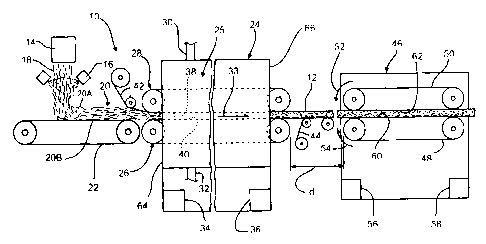
Fig. 1 is a schematic elevational view of an apparatus for forming smooth
surface
board from fibrous material according to the invention.
Fig. 2 is a schematic eleyational view of an alternate embodiment of the
pulling
apparatus illustrated in Fig. 1.
DETAILED DESCR7PTlON AI~jD PREFERRED
EMBODIMENTS OF THE INVENTION
Referring now to the drawings, there is shov~m in Fig. 1 an apparatus 10 for
3o manufacturing a smooth surface board 12 according to the invention. In the
illustrated
manufacturing process, molten glass is supplied from a furnace (not shov~m)
via a
forehearth (not shown) to a fiberizer l4. Binder applicators 16 then apply,
preferably by
2

CA 02467669 2004-05-19
spraying. a binder on the veils of fibers l8 produced by the liberizer l4. The
fibers are
collected as pack 20 on a collection conveyor 22. The binder can be a phenol-
formaldehvde binder. or any other desired ype of binder. It will be
appreciated that the
pack 20 can be produced by any desired alternate method. many of which are
known in the
art.
The uncured pack 20 is then passed through an oven 24 on a first conveyor
assembly 25. Preferably. the uncured pack 20 is passed through the oven 24
between a
first lower conveyor 26 and a first upper conveyor 28 of the first conveyor
assembly 25.
and emerges as the cured smooth surface board 12. Since the apparatus of the
invention is
primarily used for manufacturing board products having a smooth surface. the
cured
fibrous material v~Jill be referred to as smooth surface board. The pack 20 is
cured within
the oven 24 by hot curing gases. such as hot air. The hot curing gases can be
supplied to
the oven 24 from a source of hot gas (not shown) via a supply duct 30. The
curing gases
can be removed from the oven 24 via an exhaust duct 32.
t 5 The first lower conveyor 26 and the first upper conveyor 28 are preferably
foraminous, such as foraminous belts. although such foraminous belts are not
required.
Any conveyor means suitable for carrying the uncured pack 20 through the oven
24, ~~hile
enabling the flow of curing gases through the pack 20. can be used for the
conveyors 26
and 28. The first lower conveyor 26 and the first upper conveyor 28 are
preferably moved
2o in the direction of the arrow 33 by motors 34 and 36. respectively.
At the beginning of the curing process. the uncured and therefore unhardened
surfaces of the pack can be pressed into the openings in the foraminous belts
of the
conveyors 26 and 28. This pressing can cause undesirable embossing of the
pattern of belt
surfaces 38 and 40. respectively, onto the finished board 12.
?5 To prevent such embossing, and to produce a board l2 having at least one
relatively smooth face. a smoothing process. herein after referred to as
skidding, can be
used. It will be understood that skidding will refer to the process of moving
or driving one
conveyor, such as the first upper conveyor 28. at a speed faster relative to
the first lower
conveyor 26. The first upper conveyor 28 thereby also moves at a speed faster
relative to
3o the upper surface 20A of the pack 20. Accordingly, the surface 40 of the
first lower
conveyor 26 moves the pack 20 in the direction of the arrow 33, while the
surface 38 of
the first upper conveyor 28 moves Easier. or skids. relative to an upper
surface 20A of the
3

CA 02467669 2004-05-19
pack 20. Preferably. the surface 38 of the first upper conveyor 28 moves
within the range
of from about 0.4 to about 4.0 percent faster relative to the speed of the
first lower
convenor 26.
Such skidding smoothes the upper surface 20A of the pack 20. It will be
understood that such skidding can also be provided by driving the first lower
conveyor 26
at a speed faster relative to the first upper convenor 28. Preferably. the
belt surfaces 38
and 40 are substantially non-gripping. such that either or both of the
conveyors 26 and 28
can skid relative to the respective surfaces of the pack 20.
Applying a mat facing 42 to a surface of the pack 20 can enhance the smoothing
effect caused by the relatively faster moving conveyor 28. if desired, the mat
facing 42
can be applied to the upper surface 20A of the pack 20. as shov~m in Fig. 1.
The mat
facing 42 can be anv desired mat facing such as polyester/glass mat. Although
the mat
facing 42 is shown only being applied to the upper surface 20A of the pack 20
in Fig. 1, it
will be understood that the mat facing 42 can also be applied to a lower
surface 20B of the
pack 20, or can be applied to both the surfaces 20A and 24B of the pack 20.
A pulling apparatus or second conveyor assembly 46 is provided downsueam of
the oven 24. As sho~~n in Fig. 1. the second conveyor assembly 46 includes a
second
lower conveyor 48 and a second upper convenor 50. The second lov~~er com~eyor
48 and
the second upper conveyor 50 are preferably moved in the direction of the
arrov,=s 52 and
20 54 by motors 56 and 58. respectively. Preferably. the second lower conveyor
48 and the
second upper convenor 50 of the second conveyor assembly 46 provide sufficient
pressure
and/or surface area relative to the smooth surface board 12, so as to not skid
or slip v~~hen
engaging the smooth surface board 12.
The second lo~~er conveyor 48 and the second upper conveyor 50 are preyerably
25 formed of any flexible belt material. More preferably. conveyor surfaces 60
and 62,
respectively, of the second lower conveyor 48 and the second upper conveyor 50
are
gripping surfaces. As used herein, such a gripping surface is defined as
having a
coefficient of friction greater relative to the coefficient of friction of the
surfaces 38 and 40
of the first lower conveyor 26 and the first upper conveyor 28, respectively.
It will be
3o understood that the second conveyor assembly 46 can be positioned at any
desired
distance d from the oven 24 and the first conveyor assembly 25 to provide
sufficient
support to the smooth surface board 12.
4

CA 02467669 2004-05-19
In operation. the pack 20 enters an inlet end 64 of the oven 24 where the pack
24 is
compressed and cured as herein described. The cured pack 20 then exits an
outlet end 66
of the oven as the smooth surface board 12. Preferably. the smooth surface
board 12 is
relatively rigid and dense. such as for example. a board having a densiy
within the range
of from about 2 pounds per cubic foot to about 8 pounds per cubic foot.
After curing in the oven 24. a second layer of material. such as a foil-scrim-
krafl
(FSK) layer 44. or a layer of any desired material (not shown). can be applied
to the lower
surface 20B (as viewed in Fig. 1 ) of the smooth surface board 12, as shown in
Fig. 1. Any
desired conventional adhesive can be used to adhere the FSK layer 44 to the
smooth
surface board l2. It will be understood that the FSK layer 44 can also be
applied to the
upper surface 20A of the pack 20. or can be applied to both the surfaces 20A
and 20B of
the pack 20. Although the FSK layer 44 is illustrated in Fig. 1 as being
applied to the
smooth surface board 12 upstream of the second conveyor assembly 46. it will
be
understood that the FSK layer 44 can also be applied dov~mstream of the second
conveyor
assembly 46.
The second conveyor assembly 46 is driven at a speed different from the speed
of
the speed of at least one of the first lower conveyor 26 and the first upper
conveyer 28.
Preferably. the second conveyor is driven at a speed different from the speed
of both the
first lower conveyor 26 and the first upper conveyer 28.
2o By controlling the speed of the smooth surface board 12 with the second
conveyor
assembly 46, the speed of the pack 20 through the oven 24 and thereby the
smoothing of
the pack surfaces 20A and 20B, can also be controlled. For example, by driving
the
second conveyor assembly 46 at a speed substantially equal to the speed of the
slowest
conveyor (that is. the first lower conveyor 26) of the first conveyor assembly
25. the lower
surface 20B of the pack 20 is engaged by and carried on the first lower
conveyor 26, while
the first upper conveyor 28 skids along the upper surface 20A of the pack 20.
Alternately. the second conveyor assembly 46 can be driven at a speed faster
relative to both the speed of the first lower conveyor 26 and the first upper
conveyor 28.
By moving the smooth surface board l2 at a speed faster than both the first
lower
.conveyor 26 and the first upper conveyor 28. the first lower conveyor 26 and
the first
upper conveyor 28 are then caused to skid along the relatively faster moving
lower and
5

CA 02467669 2004-05-19
upper surfaces 20A and 20B of the pack 20. respectively. The lower and upper
surfaces
20A and 20B of the pack 20 are thereby both smoothed.
Additionally. the second convenor assembly 46 can be driven at a speed slower
relative to both the speed of the first lower convenor 26 and the first upper
conveyor 28.
By moving the smooth surface board 12 at a speed slov~~er than both the first
lov~~er
conveyor 26 and the first upper conveyor 28. the first lower conveyor 26 and
the first
upper conveyor 28 are then also caused to skid along the relatively slower
moving lower
and upper surfaces 20A and 20B of the pack 20. respectively. The lower and
upper
surfaces 20A and 20B of the pack 20 are thereby both smoothed.
An alternate embodiment of the pulling apparatus is shown generally at 68 in
Fig.
2. The pulling apparatus 68 includes at least one v~~heel 70 having a
plurality of spikes 72
for engaging at least one surface of the smooth surface board 12. The method
of operation
of the pulling apparatus 68 is substantially identical to the method of
operation of the
pulling apparatus or second conveyor assembly 46. and v~~ill not be described
herein. It
will be understood. however, that the method of the invention can be
satisfactorily
performed with any desired pulling apparatus.
The principle and mode of operation of this invention have been described in
its
preferred embodiments. However, it should be noted that this invention may be
practiced
otherwise than as specifically illustrated and described v~~ithout departing
from its scope.
6

Representative Drawing
A single figure which represents the drawing illustrating the invention.
Administrative Status

2024-08-01:As part of the Next Generation Patents (NGP) transition, the Canadian Patents Database (CPD) now contains a more detailed Event History, which replicates the Event Log of our new back-office solution.

Please note that "Inactive:" events refers to events no longer in use in our new back-office solution.

For a clearer understanding of the status of the application/patent presented on this page, the site Disclaimer , as well as the definitions for Patent , Event History , Maintenance Fee  and Payment History  should be consulted.

Event History

Description Date
Inactive: IPC deactivated 2020-02-15
Inactive: IPC removed 2019-05-06
Inactive: IPC assigned 2019-04-08
Inactive: IPC removed 2019-04-08
Inactive: IPC assigned 2019-04-08
Inactive: IPC expired 2012-01-01
Time Limit for Reversal Expired 2009-05-19
Application Not Reinstated by Deadline 2009-05-19
Deemed Abandoned - Failure to Respond to Maintenance Fee Notice 2008-05-20
Letter Sent 2008-05-12
Inactive: IPC from MCD 2006-03-12
Inactive: Cover page published 2004-12-26
Application Published (Open to Public Inspection) 2004-12-26
Inactive: First IPC assigned 2004-07-27
Letter Sent 2004-07-02
Application Received - Regular National 2004-06-21
Filing Requirements Determined Compliant 2004-06-21
Inactive: Filing certificate - No RFE (English) 2004-06-21
Inactive: Single transfer 2004-06-01

Abandonment History

Abandonment Date Reason Reinstatement Date
2008-05-20

Maintenance Fee

The last payment was received on 2007-05-07

Note : If the full payment has not been received on or before the date indicated, a further fee may be required which may be one of the following

  • the reinstatement fee;
  • the late payment fee; or
  • additional fee to reverse deemed expiry.

Please refer to the CIPO Patent Fees web page to see all current fee amounts.

Fee History

Fee Type Anniversary Year Due Date Paid Date
Application fee - standard 2004-05-19
Registration of a document 2004-06-01
MF (application, 2nd anniv.) - standard 02 2006-05-19 2006-05-08
MF (application, 3rd anniv.) - standard 03 2007-05-21 2007-05-07
Registration of a document 2008-03-03
Owners on Record

Note: Records showing the ownership history in alphabetical order.

Current Owners on Record
OWENS CORNING INTELLECTUAL CAPITAL, LLC
Past Owners on Record
DAVID W. THOMAS
Past Owners that do not appear in the "Owners on Record" listing will appear in other documentation within the application.
Documents

To view selected files, please enter reCAPTCHA code :


To view images, click a link in the Document Description column. To download the documents, select one or more checkboxes in the first column and then click the "Download Selected in PDF format (Zip Archive)" or the "Download Selected as Single PDF" button.

List of published and non-published patent-specific documents on the CPD .

If you have any difficulty accessing content, you can call the Client Service Centre at 1-866-997-1936 or send them an e-mail at CIPO Client Service Centre.


Document
Description 
Date
(yyyy-mm-dd) 
Number of pages   Size of Image (KB) 
Abstract 2004-05-19 1 21
Description 2004-05-19 6 311
Claims 2004-05-19 4 157
Drawings 2004-05-19 1 25
Representative drawing 2004-11-25 1 12
Cover Page 2004-12-03 1 42
Filing Certificate (English) 2004-06-21 1 158
Courtesy - Certificate of registration (related document(s)) 2004-07-02 1 105
Reminder of maintenance fee due 2006-01-23 1 110
Courtesy - Abandonment Letter (Maintenance Fee) 2008-07-15 1 173
Reminder - Request for Examination 2009-01-20 1 118
Correspondence 2008-05-12 4 133