Note: Descriptions are shown in the official language in which they were submitted.
CA 02467921 2004-05-20
DEVICE FOR CONNECTING A
MULTILAYERED WEB BY ULTRASOUND
DESCRIPTION
The invention concerns a device for the binding together
of a multilayered material band by means of exposure to
ultrasonics in a gap. The said gap is formed between an
ultrasonic oscillator and an oppositely situated responder
thereto.
DE 44 39 284 C3 describes an apparatus for the
continuous ultrasonic treatment of a material band. by means
of an ultrasonic oscillator and an oppositely situated
responder. The produced material band can be composed of a
varied multiplicity of layers, laid one on the other, which,
as individual layers can be fed into a gap. In accord with
the ultrasonic intensity in the gap, the band of layers can
be bonded together or cut. Relative to the width of the band,
the work-zone of bonding is narrow.
In another instance, DE 100 27 735 C1 discloses such a
ultra sonic material band-processing apparatus, wherein an
already loosely stratified, multilayer material band is
introduced into a gap between an ultrasonic oscillator unit
and an oppositely situated responder. The binding between the
strata is carried out in an area of welding which is narrow
as compared to the width of the said band. By conducting the
individually layered band through the said gap, the loose,
stratified layers are welded together, since.each layer of
the multiple strata is a weldable and flexible. For this
operation, thermoplastic layers are necessary, to meltingly
react to the heat generated in the ultrasonic gap f field and
form a bond between the individual layers.
It is the purpose of the invention to provide a device
for binding, by ultrasonic action, a multilayer material
band, wherein a broader band of action of such an ultrasonic
-1-
CA 02467921 2004-05-20
device is made possible. This purpose is achieved by the
features of claim 1.
Briefly, the following possible areas of bonding are
furnished by the device, in accord with either claim 1 or one
S of the subordinate claims:
-- a continuous or discrete connection of large areas of
the individual layers of the material band, which
connections extend essentially over the entire width of
the material band,
-- the binding of the material band layers without the use
of thermoplastic additives,
-- the working of one or more of the layers of the material
band and subsequent binding of the material band with
the same equipment, that is to say, the same parts of
the equipment,
-- the optimizing of the energy expenditure during the use
of ultrasonic binding in discrete or apportioned binding
zones,
-- the micro-splice joining of border edges of fiber
containing material band layers which lie one upon the
other,
By the production of corrugated boxboard by means of a
device in accord with one of the claims, it is possible to
achieve one or more of the following advantages:
-- a lessening of the moisture content input during the
manufacture of the corrugated boxboard,
-- a diminution of heat intake upon the binding of the
material band layers,
-- a lessening of the energy requirements upon the drying
of the already bound boxboard,
-- a lessening or the omission of a binding material band,
such as an adhesive,
-2-
CA 02467921 2004-05-20
-- substantial reduction of the installed size of the
corrugating machine,
-- faster reversal of the machine, especially by the
omission or the reduction of necessary preheating
phases, and
-- the omission or the shortening of the run-in phase after
restart of the equipment.
In the case of the device, as presented in claim 1, a
plurality of layers for a material band are bound together by
ultrasonics in a gap between a first ultrasonic oscillator
and at Least one first oppositely positioned receptor. At
least one, first, flat, individual material band is designed,
along with a second, and these are respectively introduced by
a first and a second feed apparatus into a first gap.
Advantageously, the first and the second individual material
bands are brought directly to said gap, or enter therein,
ready for the multiplayer binding procedure.
In one particular embodiment, the introduced second
individual material band is supplied with corrugated
profiling. Also, the introduced first or even additional
individual material bands can be so profiled. Profiling is to
be understood in that, the individual material band possesses
a three dimensional, regular or irregular surface structure.
Thus the top or the bottom side of the second material band
is not smooth, but is characterized by elevations and
depressions. Advantageously, the profiling, relative to the
travel path of the material band, is aligned either
longitudinally or transversely. The profiling can be, for
example, in straight lines, in zigzag formation, or in a
wavelike configuration. For the manufacture of a durable
binding structure, the profiled individual material band
should be shaped in wave form or have sharp creases. This is
-3-
CA 02467921 2004-05-20
in order that the said individual material bands may bond
into a rigid, lightweight structure.
Advantageously, the first ultrasonic oscillator is
proximal to the first individual material band and the
corresponding receptor borders the second individual material
band. In this way, the ultrasonic oscillator lies near the
surface of the first individual material band . The
separation distance between the ultrasonic emitting surface
of the first ultrasonic oscillator and the bonding zone
between the first and the second, but profiled individual
material band is then at its minimum.
If the second feed apparatus possesses a profiling roll-
pair for the second individual material band, then it is
possible that a binding between the first and the second
individual material bands can be carried out in one apparatus
with the advantage, that the second individual material band
is already profiled. The profiled roll-pair produces, for
example the above mentioned profiling of the second
individual material band. In the case of a profile, wherein
the corrugations run transverse to the length of the material
band, then the profile rolls have their own circumferential
ridge and valley contours disposed parallel to their own
axes. Conversely, if the profiling on the material band is to
extend lengthwise, then the roll ridge and valley profiling
will be circumferential. Particularly advantageously, the
profiling roll-pair possesses two ridge and valley rollers,
as these, for example, are known in the design of a
corrugating line for corrugated boxboard.
In an entirely exceptionally favorable embodiment, one
of the profiled rolls of the profiled roll-pair acts as a
responder to an ultrasonic oscillator. Thereby, the second
individual material band is first impressed by the said
profile roll-pair and subsequently the profiling is in place
-4-
CA 02467921 2004-05-20
to enhance the binding between the first and second
individual material bands. On this account, no separate,
specially designed counter responder is required for the
first ultrasonic oscillator.
The peaks, or the extended projections, of the first
profile roll, most closely approach the ultrasonic surface of
the first ultrasonic oscil7,ator. By means of an ultrasonic
reflection surface, the ultrasonic radiation is principally
reflected away from the profile roll and ultrasonic
penetration into the profiling roll is minimized.
Advantageously, the ultrasonic reflection surface at the area
of the peaks or on the projections of the profiled roll are
so designed, that the ultrasonic waves reflect into the gap.
Thereby the supersonic impact pressure in the gap is
increased. Thus, with advantage, the sound to the first
ultrasonic oscillator apparatus is reflected back, so that
the field within the gap is increased even further. Thereby,
the probability of an establishment of a standing-wave in the
gap is improved.
For the first ultrasonic oscillator, a first generator
unit is assigned, the power of which can be varied on a time
scale, so that the power input modulations can be made to
match the requirements of current bonding or bonding about to
take place: The power draw can be lessened and likewise, the
input of heat into the material band is correspondingly
reduced. In this way, for example, discrete binding areas
between the material bands can be created. Should a complete
areal binding of the material bands be desired, then the
above discrete binding zones can be distributed surfacewise
over the width and length of the material band.
If the second individual material band has
longitudinally disposed, periodic profiling, then,
advantageously, the time-period of the changing of the power
-5-
CA 02467921 2004-05-20
modulation is made by the first generator unit to correspond
to that of said periodic profiling. This is done in concert
with the rate of travel of the material band through the gap.
Advantageously, the pulse length of the power modulation is
in itself changeable, so that by a changing through-put speed
of the material band, pulse lengths can be made to coincide
with one another. Advantageously, the service apparatus
diminishes its power maximum, if a length of the material
band is pulled through the gap, wherein the second individual
material band lies upon the first individual material band.
In this way, advantageously, power is brought into the said
length and or energy is transferred into the material band,
whereby also, in fact, binding between the bands occurs.
The power modulation can be done by inducing a beat.
Therewith, a material band protective operation for an
ultrasonic oscillator is made available, since no power peaks
occur and thus excessive frequencies of the ultrasonic
oscillator are avoided. The beat can be attained by means of
modulations with the first generator unit itself. Or the
modulation is achieved through a tuning between the exciting
frequency for the ultrasonic oscillator and the inherent
frequency of the said ultrasonic oscillator. The frequency of
the beat can be adjusted by the difference in frequency
between the exciting frequency and the inherent frequency of
the ultrasonic oscillator. In this way, a matching of the
pulse length of the beat to the speed of the material band as
it passes through the gap is enabled.
In an advantageous embodiment, a third feed apparatus
conducts a third, individual material band into a second gap
between a second ultrasonic oscillator and at least one
second responder thereto. In the second gap, the material
bands (for example, consisting of the bonded first and the
second individual material bands) are bound to this third,
-6-
CA 02467921 2004-05-20
additional, individual material band. In the case of one
embodiment, the third individual material band can be
directed to cover only the surface of the second individual
material band. If the second individual material band is, for
example, profiled, then it becomes possible, by means of the
feed of a non-profiled third individual material band to
construct a sandwich structure, as these are customarily
known in corrugated boxboard.
If the second ultrasonic oscillator is placed proximal
to the third individual material band, then the ultrasonic
emitting surface of the second ultrasonic oscillator borders
on the contacting area between the second and the third
individual material band. In some embodiments, the second
responder, which coacts with the second ultrasonic
oscillator, is itself a smooth roll, or a profiled roll,
which advantageously, is provided with a profiling, which is
made to correspond to that of the first profile roll.
In one embodiment, a bowl-like depression in a
ultrasonic reflection surface and/or the mentioned "hill",
i.e., a projection of the ultrasonic reflection surface of a
profile roll is filled with a substance, which has a lesser
ultrasonic reflectivity than does the material of the said
ultrasonic reflection surface. Thereby, the ultrasonic sound
penetrates from the gap through the filling material band and
is reflected primarily from that side of the ultrasonic
reflection surface, which is now behind the said filling
substance.. By means of the filling of the said bowl-like
depression, an even or an a outward extending convex surface
is formed, so that, in the said bowl, no contamination can
accumulate. Conversely, by means of the filling over the
reflection surface, a rise or a projection can result in a
profiling, which matches that of the directly opposing roll,
whereby the reflection is reinforced.
-7-
CA 02467921 2004-05-20
In another embodiment, the device has a first or a
second displacing unit for the changing of the width of the
first or the second gap. In this way, the gap can be made to
fit different material band thicknesses. Also, the gap width
S adjustment can be done in such a manner, that with the chosen
beat frequency of the first and/or the second ultrasonic
oscillator, a standing wave, i.e., a resonance can be formed.
The resonance conditioning, that is to say, the establishment
of a standing wave, can also be created within an unchanged
gap by an alteration of the said beat frequency. In the case
of resonance, the sound wave pressure in the zone of the
pressure node is at its greatest, when the air or material
band movement in the zone of said pressure nodes is also at
its greatest. By means of an alteration of the gap width
and/or the excitation frequency, the position of the said
pressure node is displaced. If a pressure node is relocated
into that area of the binding surfaces, then at that point
the greatest material movement is produced.
In the case of another embodiment, the first or the
second operational gap extends itself at least essentially
over the entire width of the multilayered band.
Advantageously, the first and/or the second ultrasonic
oscillator is subdivided sectionwise, and possesses a
plurality of ultrasonic beats, so that by means of ON and OFF
switching, of individual ultrasonic beats or groups of
ultrasonic beats, the field gap width can be adapted to the
width of the material band. In this way, at least two layers
of the material band can be bound together as a whole
continuous surface, or in subdivided, discrete areas.
In another embodiment, by means of a layering apparatus,
effective on the first, second and/or the third individual
material band, a liquid can be applied, or so to say, can be
provided as an additional coating. This liquid application
_g_
CA 02467921 2004-05-20
can be done, for example, by means of a roll turning along
the surface of the material band or by means of a spray gun
or the like. One such liquid application on areas to be bound
together between material bands, normally suffices. For an
S example of liquid application, an aqueous film can be
deposited on the ridges of the profiled, second individual
material band, which are to be bound in the gap with the
first and/or the second individual material band.
In still another embodiment, an additive apparatus is
provided, which has an additional profile roll-pair for the
profiling of yet another individual material band. Beside the
profiled, second individual material band, therewith a
further profiled individual material band is introduced into
an extra gap between an additional ultrasonic oscillator and
its matching responder. In this way, a multilayered material
band with at least two profiled individual material bands can
be provided. Advantageously, the profiling of this additional
individual input band is designed to be displaced, that is to
say, to be transverse to the longitudinal direction of the
band. In this way, it becomes possible to form boxboard with
a double layered, corrugated band.
The just described apparatus, among other advantages,
adapts itself well to the manufacture of corrugated boxboard.
For the binding of the paper bands to one another, it is not
necessary to employ a binding material, that is, especially,
no adhesive is required. However, it is not excluded, to use
a minimum amount of a suitable adhesive, if required.
Further, the just described apparatus adapts itself to
the establishment of binding between material bands, wherein
the material contains fiber particles. This would include,
for example, paper bands or the like. It is not a
requirement, that the individual material bands to be bound
together be thermoplastic components, or especially contain
_g_
CA 02467921 2004-05-20
thermoplastic plastic material , nor is it required that an
adhesive be applied. Thereby, the durability of the material
bands is improved and/or the value thereof for recycling is
enhanced.
In the case of material bands with fiber particulate,
the following binding actions, alone, or in combination with
differing proportioning can be activated:
-- the microsplicing of the fiber particulate of a
individual material band with the fiber particles of
another individual material band. When this is
undertaken, then, by means of mechanical movement in the
ultrasonic field, the particles are released from their
original impaction and form, with the likewise released,
immediately proximal other fiber particulate, a new
binding,
-- fluids within the material band or in loose condition on
the material band are atomized, and so effect a
mechanical dissolution of the individual material band
in limited invasion areas, so that the so disassociated
areas can reform themselves,
-- by means of thermal action, the binding material band
releases the individual material band (for instance, by
the intrusion of water), whereupon, the material band
hardens, or "cures", in a reformation of a new binding
between two individual material bands which are proximal
to one another.
In the manufacture of corrugated boxboard, it has been
determined, that no adhesive is necessary for the binding of
the paper bands. An application of water prior to the binding
is not required, although the application of a small quantity
of moisture does enhance holding power between the paper
bands. Compared to the conventional production methods for
corrugated boxboard, a drying operation must be a subsequent
- 10-
CA 02467921 2004-05-20
operation for the binding equipment. With the invention, a
drying machine section can be omitted or may be substantially
reduced in size. By means of the microsplicing of fibers of
the adjacent paper bands, the moisture-stability of the so
manufactured corrugated boxboard is essentially improved. As
compared to conventional corrugated boxboard containing
adhesive, paper bands of the invention dissociate only after
long subjection to high humidity.
Embodiment examples are explained in greater detail with
the aid of drawings. There is shown in:
Fig. 1 a schematic cross-section of a modular
corrugated boxboard manufacturing machine,
Figs. 2A and 2B embodiments of a binding unit for a third
paper layer,
Fig. 3 a schematic cross-section of a corrugating
boxboard machine in accord with a second
embodiment,
Figs. 4A to 4C embodiments of ultrasonic emission and
reflection surfaces,
Figs. 5A and 5B inserts for ultrasonic reflection surfaces,
Fig. 6 a time diagram of power modulation as
assigned to a running corrugated boxboard
machine,
Figs. 7A and 7B two embodiments of the arrangement of
ultrasonic oscillators transverse to the
paper band, and
Figs. 8A and 8B a binding pattern arising from the arrange-
ment of 7A and 7B.
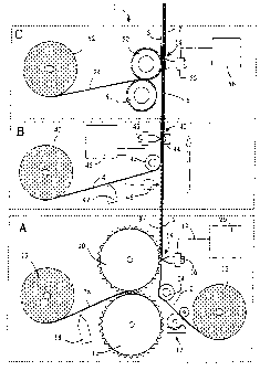
Fig. 1 shows a schematic cross-section through a modular
corrugated boxboard machine 1. Three modules, namely A, B and
C of the corrugation machine 1 are presented. In module A, a
first cover band 2 is bound to a first corrugated band 3. In
module B, a second cover band 4 is bound to the already bound
-11-
CA 02467921 2004-05-20
bands 2, 3. Onto the single corrugated layer boxboard 6
issuing from the module B, in module C a second corrugated
band 5 is bound. Not shown, a module D can be placed
thereafter, which adds onto the second corrugated band 5 a
third cover band, so that a double layered corrugated
boxboard 7 has been produced with three cover bands. In
module A, a ribbed roll-pair 10, 11, produces a first
corrugated band 3 from the paper band 3a. The first
corrugated band 3 is profiled transverse to the direction of
IO the band. In module C, another ribbed roll-pair 50, S1
produces from the paper band 5a the second corrugated
boxboard band S. The rib impressions, i.e, the profiling, of
this second corrugate boxboard band 5 is aligned in the
longitudinal direction of the band, so that, in the case of
the double, corrugated layer boxboard 7, the profiling of the
corrugated boxboard bands 3, 5 is crossed. The arrow, which
points from below to above, shows the running direction for
the corrugated boxboard band. The rolls which contact or
touch both the paper bands or the cover bands rotate with a
circumferential speed which corresponds (approximately) to
the travel speed of the bands.
The paper bands, 2, 3a, 4, 5a are, in respective order,
fed from paper supply rolls 12, 13, 40 and 52. In module A,
the cover band 2, which issues from the first paper supply
roll, is diverted by a change of direction roll 14 and is
introduced into a first gap 15 between the first ribbed roll
10 and a first ultrasonic oscillator 16. Optionally, between
the first paper supply roll 12 and the first gap 15, however,
or even more advantageously, between the first change of
direction roll 14 and the first paper supply roll 12, can be
placed an adhesive roll 17. The adhesive roll 17 possesses an
application roll, a pressure roll and an adhesive container,
through which the said adhesive roll can turn. The
- 12-
CA 02467921 2004-05-20
application of the adhesive is carried out transversely to
the first cover band 2. Optionally, between the second supply
paper roll 13 and the ribbed roll-pair 10, 11, a moisturizer
18 could be placed, which would dispense a thin, aqueous film
on the paper band 3a. The moisturizer 18 could also be
provided between the first gap 15 and the first paper supply
roll 12 in the place of the adhesive applicator 17. Another
moisturizer could be supplied in addition to the existing
moisturizer 18 for the moisturizing of the paper bands 3a
and 2 .
In module A, the ultrasonic oscillator 16 is connected
with a line 19 to an ultrasonic generator 20. The ultrasonic
emission is to be radiated from the surface bordering on the
first gap 15 and into the said gap by means of the ultrasonic
oscillator 16. On the opposite side of the gap 15 the
ultrasonic emission impinges on an outer surface of the
ribbed roll 10.
Fig. 7A shows a schematic presentation of the ultrasonic
oscillator 16, which is located opposite to the ribbed roll
10. The ultrasonic oscillator 16 is assembled from a
plurality of adjacently situated vibratory sections 16 a to
d. The emitting surfaces of the oscillating sections are
longitudinally aligned and run parallel to the roll axis.
Each vibratory section 16 a-d, by means of a line 19 a-d, is
connected with a power driver 20a-d of the ultrasonic
generator 20. The generator 20 can be so operated, that the
phase, amplitude and frequency of the power driver are
identical. Phase, power, amplitude and frequency, however,
can partially differ from power driver to power driver for
the optimizing of the operation of the individual beat
sections 16 a-d. An example of this would be, if the power
output be regulated to be constant in value, while the
frequency for the creation of a resonance in the first gap 15
-13-
CA 02467921 2004-05-20
is optimized. One or more beat sections 16a-d allow
themselves to be energized or de-energized, only in order to
yield an ultrasonic power, at the zone where the corrugated
boxboard, that is, the cover band and/or the corrugated band
S actually runs through. By this ON and OFF switching, the
active gap length is adjusted to the necessary corrugated
boxboard breadth. The ultrasonic oscillators 43, 70 and/or
71, which are described below, can be accordingly constructed
and operated.
In module B the second cover band 4 is diverted in its
travel by a second change of direction roll 41 to the already
bound band comprised of the first cover band 2 and the first
corrugated band 3. These bands are being introduced into a
second gap 42 between a second ultrasonic oscillator 43 and a
reflector line 44 to allow bonding. The second ultrasonics
oscillator 43 is energized by a second ultrasonic generator
45, and can be designed to correspond to the first ultrasonic
oscillator 16. In the second gap 42, the second cover band 4
is brought into contact with the corrugated band 3 and these
are bound together along their common touching areas.
A separating distance sensor 46 captures the ridges and
valleys of the first corrugated band 3 and sends the signal
thereof to the second ultrasonic generator 45. This is done
in order to permit a time related power modulation, which
would be dependant upon the succession and positions of the
said hills and valleys. With the forward speed of the
corrugated boxboard travel in this area known, a power
maximum of the ultrasonics could then be issued, with a lead
in time, from the second ultrasonic oscillator 43 in such a
manner, that in the inter-layer contact area between the
first corrugating band 3 and the second cover band 4, a
maximal power impulse would be made available. Optionally,
between the third paper supply roll 40 and the second gap 42
-14-
CA 02467921 2004-05-20
there could be installed a moisturizing element 47 or (not
shown) an adhesive applicator, which, respectively, would
correspond to the moisturizing element 18 or to the adhesive
applicator 17 in module A.
The single layer corrugated boxboard is then further
transported at the same speed to module C, where it enters a
third gap 54. The second corrugated band 5, is fed into this
third gap 54. Band 5 has been produced by the coaction of the
third and forth profiled rolls 50, 51. The third gap 54 is
bordered upon surface with a computer controlled, ultrasonic
oscillator 55 and bordered on the other surface by the third
profiled roll 50. The computer controlled, ultrasonic
oscillator 55 is activated by the ultrasonic generator 56. In
this third gap 54, the second corrugated band 5 and the
second cover band 4 are bound together, to that a double
layered corrugated boxboard 7 has been created.
Fig. 7B shows a schematic, top view of the computer
controlled, ultrasonic oscillator 55. This computer
controlled, ultrasonic oscillator 55 is assembled from
oscillator sections 55 a-n. The radiating surfaces of the
individual emission sections 55 a-n are designed to run in a
longitudinally alignment, in the direction of the
circumference of the roll. Additionally, the emitting
surfaces are bent with a radius, which more or less
represents the radius of the roll plus the width of the gap.
The width of the said emitting surfaces of an emission
section can extend themselves over several ridges of the
third ridged roll 50. It is also possible, that per ridge of
the ridged roll 50, an oscillation section can be provided.
This provision could extend the section over a distance of a
multiple of ridge widths. As is seen in the unit of Fig. 7A,
the group of individual oscillation sections 55 a - n in Fig.
7B can be synchronously driven together, that is, with the
- 15-
CA 02467921 2004-05-20
same phase, frequency and power. Alternately, each section
oscillator could be individually optimized, as has already
been described with reference to Fig. 7A.
Figs. 2A and 2B show embodiments of the module B.
S Insofar as nothing else is given, the same elements are
provided. In the case of Fig. 2A, a second gap 42a, between
the second ultrasonic oscillator 43 and the change of
direction roll 41 is provided. In this case, the reflector
line 44 is omitted. The power output of the second line
ultrasonic oscillator 43 can once again be so synchronized,
that a power maximum is then furnished, when the cover band 4
touches the first corrugated band 3.
In the case of the embodiment as shown in Fig. 2B,
instead of the reflector line 44, a ridged roll 48 is
1S provided, the ridge arrangement of which corresponds to the
ridge pattern of the first corrugated band 3. This ridge roll
48 is so synchronized with the through-put of the first
corrugated band 3, that a projection of the ridge roll 48
then acts as a gap surface of the second gap 42b, since the
first corrugated band 3 lies on the second cover band 4.
Instead of the change of direction roll 41 in Fig. 2A, that
function can be taken over by the said ridged roll 48:
Fig. 3 shows an embodiment, of an integrated corrugated
boxboard unit 60. From a first paper supply roll 62, a first
cover band 61 is conducted over a first change of direction
roll 67. From a second paper supply roll 64, a second cover
band 63 runs over a second change of direction roll 68. In a
simultaneous action, a first corrugated band 65 is produced
from a paper band 65a by a ridged roll pair 66. The paper
band 65a is conducted by means of a third paper supply roll
73 to the said ridged roll pair 66. The three bands, 61, 65,
63 meet together in the gap 69, which is formed by two
oppositely bordering line ultrasonic oscillators 70, 71. The
-16-
CA 02467921 2004-05-20
line ultrasonic oscillators 70, 71, are driven by an
ultrasonic generator 72. The line ultrasonic oscillators 70,
71 can be designed to essentially correspond to the line
ultrasonic oscillator which is shown in Fig. 7A. The
ultrasonic oscillators 70, 71 are so set, one against the
another, that they apply a half wave cross pattern on the
first corrugated band 65 which carries over to the bands 61
and 63. In this case, the first corrugated band 65 lies on
the first cover band 61 in the area of the ultrasonic
producing surface of the ultrasonic emitting surface of the
first line ultrasonic oscillator 70, when the first
corrugation band 65 lies on the second cover band 63 in the
area of the ultrasonic producing surface of the second line
ultrasonic oscillator 71. It is also possible, to operate
passively, one of the line ultrasonic oscillators 70, 71 so
that this will be excited to oscillation by the ultrasonics
of the other line ultrasonic oscillator unit.
The bands 61, 63, and 65 lying closely, one on the
other, are bound together in the gap 69, allowing the
constructed size of the integrated corrugating machine module
60 to be significantly reduced. It is further possible, that
moisture and/or adhesive can be applied one sidedly or two
sidedly onto the first cover band 61, onto the second cover
band 63 and/or onto the first corrugated band 65. This would
be effected by a moisturizing element and/or an adhesives
applicator placed in correspondence to Fig. 1. Further
modules in the series of C, B, D or B, D can be included.
Fig. 4A shows an enlarged illustration of a cross
section of the first ridged row 10 of the first gap 15 with
the gap width H and the forward part of the first line
ultrasonic oscillator 16. The ultra-sound emitting forward
surface of the line ultrasonic oscillator 16 has a bowl-like,
or an inward concavity, preferably of parabolic shape or even
-17-
CA 02467921 2004-05-20
formed as a partial spherical recess, so that the ultrasonic
emission focuses in the direction of the surface of the first
ridged roll. The said bowl-like depression is aligned in a
transverse direction to the paper band (that is to say,
perpendicular to the plane of the drawing). Fig. 4B shows an
embodiment of the first ridged roll 10, wherein the upper
side of the tooth 21 has been flattened. This flattening can
be designed to be bowl-like, parabolic, or spherical in
shape.
Fig. 4C demonstrates a section of the oppositely
situated line ultrasonic oscillators 70, 71 of Fig. 3,
enlarged to show some detail. The bordering surfaces of the
gap 69 are smooth, and shaped to be bowl-like, parabolic or
partially spherical. The depth runs likewise perpendicularly
to the plane of the drawing over the breadth of the line
ultrasonic oscillator, i.e., the oscillatory section thereof.
By changing the frequency, or changing the width of the gap
"h", it is possible that a standing wave can be created in
the gap 69. The standing wave can be measured as a half-wave
length, or a multiple of a half-wave length. The line
ultrasonic oscillator 71, can, as already explained, be
designed to be passive, in that it principally reflects the
radiated sound from the line ultrasonic oscillator, and if
necessary, can itself be excited into oscillation or to
resonance vibration.
Fig. 5A shows detail view of the reflector line 44 of
the module B of Fig. 1. The gap bordering surface of the
reflector Line 44 is likewise designed as a recess. The said
recess can likewise be again shaped as bowl-like, parabolic,
or partially spherical. For the avoidance of contamination
deposition the recess 441 is advantageously filled with a
substance, which exhibits on the interface area air/material
band, a slight ultrasonic reflectivity. Thereby the greatest
-18-
CA 02467921 2004-05-20
part of the gap-side impacting ultrasonics penetrates the
said material band in recess 441 and is first reflected from
the curved surface of the said recess 441. Thereby, a
directed back reflection of the impacting ultrasonic
radiation is achieved. Fig. 5B shows an enlarged cross-
section of a ridge tip of Fig. 4B, wherein the original tooth
apex 21 has an extension 211 of a substance such as the above
filling for the recess 441.
Fig. 6 shows an embodiment of the time related course of
the power dissipation by the ultrasonic generators 20, 45
and/or 72. While the material band is being pulled through a
gap 15, 42, 42a, 42b, 54 and/or 69, at that time, a power
maximum is dissipated, when one of the material bands bonds
onto one of the other material bands . This is made clear in
Fig. 6 by the first corrugated band 3, which lies against
either on the first or on the second cover band 3, 4. The
upper time diagram shows an impulse shaped account of the
power I and the lower time diagram shows a time-dependent
modulation of the vibratory amplitude A in the form of a
beat. The pulse length P is, in this connection, equal to r /
v, whereby v is the speed of transport of the corrugated
boxboard, and r is the grid dimension of the first corrugated
boxboard band 3.
Fig. 8A depicts a section of the surface of the
corrugated boxboard, if, with the arrangement of Fig. 7A a
time related power modulation in accord with Fig. 6 has been
carried out. On the corrugated boxboard surface there are to
be seen connection zones 80 which are separated from one
another according to a transverse placement of the vibratory
sections 16 a - d . In the band longitudinal direction, the
connection zones 80 correspond to the spacing of the grid
dimension r.
-19-
CA 02467921 2004-05-20
Fig. 8B shows the connection lines, where these, for
example, are produced with the arrangement of Fig. 5B. The
separating distance between the binding lines 81 correspond
to the grid dimensioning of the second corrugating band 5,
that is to say, to the separations of vibratory sections 55 a
- n. In the case of continued power supplying, to the
computer unit controlled ultrasonic unit 55, the connection
lines 81 are continuous and, in the case of power modulation,
are partially interrupted.
A corrugated boxboard machine need not be exclusively
designed on the basis of ultrasonic connection modules. One
or more of the modules A, B, C, or D can be replaced by one
or more of conventional modules. It is also possible that the
modules B, C, and/or D can be thereto attached. Conventional
modules, for example, incorporate a transfer roller, a
splicer, a preheater, a band leader, an adhesive application
device, a heater and adhesive curing apparatus, and/or
further workup equipment such as cutting and folding
machinery.
-20-