Note: Descriptions are shown in the official language in which they were submitted.
CA 02468169 2004-08-31
INTERNAL COMBUSTION ENGINE
BACKGROUND OF THE INVENTION
The present invention relates to intemal combustion engines. In an intemal
combustion
engine, the basic fiinctionality includes: (1) the intake ofa fuel-air
niixture into a combustion
chamber, (2) the compression of the fuel-air niixture, (3) the ignition of the
fuel-air mixture, and
(4) the expansion of the ignited mixture and exhausting of the combustion
gases. The resultant
release of energy in the form of expanding gas is used to power various
mechanical devices,
including vehicles.
A reciprocating intemal combustion engine is perhaps the most common form of
intemal
combustion engine. In a reciprocating intenial combustion engine, the
reciprocating niotion of a
piston in a cylinder results in the conipression of the fuel-air mixture and
the expansion of
CA 02468169 2004-05-21
WO 03/060299 PCT/US03/00477
combustion gases. The energy is transfomied from linear niotion into
rotational niotion through
connection of the piston to a crankshaft.
Most modern vehicle engines currently use a piston-cylinder arrangement in
what is
referred to as a four-stroke combustion cycle, comprised of (1) an intake
stroke, (2) a
compression stroke, (3) a combustion stroke, and (4) an exhaust stroke. In a
four-stroke
combustion cycle using a typical piston-cylinder arrangement, the piston
starts at the top of the
combustion chamber (i.e., the cylinder), and an intake valve opens. The piston
moves
downwardly within the cylinder, and the fuel-air mixture is drawn into the
cylinder through the
intake valve, completing the intake stroke. The piston then moves back
upwardly to compress
the fuel-air mixture until reaching the top of the stroke, completing the
compression stroke.
When the piston reaches ttle top of the stroke, the spark plug ignites the
compressed ittel-air
mixture, resulting in a controlled explosion that drives the piston
downwardly, completing the
combustion stroke. Finally, once the piston reaches the bottom of its stroke,
an exhaust valve
opens, and combustion gases are forced out of the cylinder by the upward
movement of the
piston back to the top of its stroke, completing the exhaust stroke and
readying the piston for a
subsequent combustion cycle.
Although comnion in vellicles, a reciprocating internal conlbustion engine
using a four-
stroke combttstion cycle does have some disadvantages. As a result, other
engines liave been
developed that use the same basic combustion principles witli sonie variation.
For exaniple, in
an internal combustion engine using a two-stroke combustion cycle, the intake
and exhaust
valves are eliniinated. Instead, intake and exhaust ports are located on
opposite sides of the
cylinder. After each expansion stroke, combustion gases tinder pressure exit
the cylinder
through the exhaust port, and a ftiel-air nlixttire is drawn in throtigh the
intake port. Although
2
CA 02468169 2004-05-21
WO 03/060299 PCT/US03/00477
there is only one expansion cycle per crankshaft revolution, a two-cycle
engine is niust less
efficient than a four-cycle engine.
Another reciprocating internal combustion engine is a diesel engine, which can
have a
four-stroke or a two-stroke combustion cycle. Unlike the above-described
engines, however, a
diesel engine draws in and compresses only air in the cylinder. This air is
compressed by the
piston to more than 450 psi, resulting in an air temperature of about 900-1100
F. At the bottom
of the compression stroke, diesel fuel is injected into the cylinder, and the
temperature of the air
within the cylinder is sufficient to cause ignition of the ftiel-air mixture
without the need for a
spark plug.
In any event, a reciprocating internal combustion engine has its
disadvantages. The
piston has a significant mass and thus inertia, which can cause vibration
during motion and liniits
the maxinium rotational speed of the crank shaft. Furthermore, sucli engines
have relatively low
mechanical and fuel efficiencies.
As a result of such disadvantages, sonie attempts have been made to propose
alternate
combustion engine designs. Perhaps the most well-known and commercially
successful of these
alternate designs is the Watikel or rotary piston engine. The Wankel engine
has a quasi-
triangular rotating piston that moves along an eccentric path to rotate the
crankshaft. Rather
than using inlet and exhaust valves, the edges of the rotating piston open and
close ports in the
wall of the combustion chamber. In other words, intake and exhaust tiniing are
controlleil solely
by the motion of the rotor.
As the piston of the Wankel engine rotates, seals mounted at its three corners
continuously sweep along the wall of the combustion chaniber. The enclosed
volumes fonned
between the piston and the wall increase and decrease through each revolution
of the piston. A
3
CA 02468169 2004-05-21
WO 03/060299 PCT/US03/00477
fuel-air mixture is drawn into an enclosed volunie, compressed by the rotation
of the piston that
decreases the enclosed volume, and then ignited with the combustion gases
being acconimodated
by and expelled through the expansion of the enclosed volume. In short, a
complete four-stroke
combustion cycle is achieved, but since there is no reciprocating motion,
higher rotational speeds
are possible.
The most pronounced disadvantage of a Wankel or rotary piston engine is the
difficulty
in adequately sealing the enclosed spaces between the piston and the wall of
the combustion
chamber that increase and decrease through each revolution of the piston. If
these enclosed
spaces are allowed to communicate with another, the engine can not properly
function.
Since development of the Wankel engine, other attempts have been made to
improve
upon its operation. For example, U.S. Patent No. 5,415,141 describes and
claims an engine that
has a central rotor and a plurality of radially sliding vanes. The vanes
rotate clockwise with the
rotor to form enclosed volumes between the vanes, the side walls of the
combustion chaniber,
and the rotor. These enclosed volumes decrease and increase in volume
throughout the
combustion cycle, with the fuel-air mixture being drawn into an enclosed
volume, compressed
by the rotation of the rotor and associated vane, and then ignited with the
combustion gases
being accommodated by and expelleci tlirough the expansion of the enclosed
volume.
Nevertheless, as with a Wankel engine, such a design still suffers from the
probleni of adequate
sealing of tlie enclosed volumes from one another. Furthennore, the drag of
the vanes along the
wall of the combustion chamber reduces power and fuel efficiency.
It is therefore an object of the present invention to provide an improved
internal
conibustion engine that avoids the problems of common reciprocating motion,
piston-type
engines.
4
CA 02468169 2004-05-21
WO 03/060299 PCT/US03/00477
It is a further object of the present invention to provide an improved
internal conibustion
engine that avoids the sealing and efficiency problems of rotary combustion
engines.
These and other objects and advantages of the present invention will become
apparent
upon a reading of the following description along with the appended drawings.
SUMMARY OF THE INVENTION
The present invention is an internal combustion engine that is generally
comprised of a
torque wheel mounted for rotation within a housing and driving a crankshaft.
The housing
defines a central cavity (or combustion chamber) in which the torque wheel and
associated
components of the engine are enclosed. The torque wheel includes a plurality
of separate arms
in a spaced arrangenient about the center of the torque wheel, thereby
defining corresponding
volumes between the respective arms. Positioned within these volumes are
substantially
identical combustion gates. Although not directly secured to the torque wheel,
the shape of the
combustion gates causes them to be tightly retained and oriented relative to
the torque wheel.
As the torque wheel rotates, the combustion gates are moved through an
elliptical path.
Air is drawn into the central cavity of the housing and fuel is introduced
into the central cavity of
the housing to create a fuel/air mixture in one of the volumes between the
respective arms of said
torque wheel and adjacent one of the combustion gates. This fuel/air mixture
is then compresseci
during the continuing rotation of the torque wheel by the pivoting and outward
movement of the
combustion gate. The fuel/air mixture is then ignited, causing a rapid
expansion of combustion
gases and itnparting a torque that causes continued rotation of tlie torque
wlieel. The conibustion
gate then pivots and moves inwardly toward the center of the torque wheel,
allowing the
5
CA 02468169 2004-08-31
combustion gases to expand, and then pivots and move outwardly again, forcing
the combustion
gases through an exhaust outlet.
Accordingly, in one aspect, the present invention provides an internal
combustion engine,
comprising: a housing defining a central cavity; a torque wheel mounted for
rotation within the
central cavity defined by said housing and driving a crankshaft, said torque
wheel having a
plurality of arms in a spaced arrangement about the center of said torque
wheel, thereby defining a
plurality of corresponding volumes between the respective arms; a plurality of
substantially
identical combustion gates positioned within said corresponding volumes, each
of said
combustion gates being mounted for rotation within a respective volume about a
pivot pin; a pair
of cam cutout plates positioned on either side of the torque wheel and within
the central cavity
defined by said housing, an elliptical cutout being defined in each cam cutout
plate with a cam
guide pin passing through each combustion gate and being received in the
elliptical cutouts
defined in each cam cutout plate, such that the elliptical cutouts serve as a
track to guide the
movement of the combustion gates; and a pair of seal plates, a seal plate
being positioned on
either side of said torque wheel, slots being defined through said seal plates
such that the cam
guide pins associated with the respective combustion gates pass through the
seal plates and are
received in the elliptical cutouts; wherein, as said torque wheel rotates, air
is drawn into the
central cavity of said housing and fuel is introduced into the central cavity
of said housing to
create a fuel/air mixture in one of said volumes between the respective arms
of said torque wheel
and adjacent one of said combustion gates, said fuel/air mixture being
compressed during the
continuing rotation of said torque wheel by the pivoting and outward movement
of said one
combustion gate as dictated by the elliptical cutouts, said fuel/air mixture
then being ignited,
causing a rapid expansion of combustion gases and imparting a torque that
causes continued
rotation of said torque wheel, the elliptical cutouts then causing said one
combustion gate to pivot
and move inwardly toward the center of said torque wheel, allowing said
combustion gases to
expand, and then said elliptical cutouts causing said one combustion gate to
pivot and move
outwardly again, forcing said combustion gases through an exhaust outlet.
In another aspect, the present invention provides an internal combustion
engine,
comprising: a housing defining a central cavity; a torque wheel mounted for
rotation within
6
CA 02468169 2004-08-31
the central cavity defined by said housing and driving a crankshaft, said
torque wheel having a
plurality of arms in a spaced arrangement about the center of said torque
wheel, thereby defining a
plurality of corresponding volumes between the respective arms; a plurality of
substantially
identical combustion gates positioned within said corresponding volumes, each
of said
combustion gates being mounted for rotation within a respective volume about a
pivot pin; and a
pair of cam cutout plates positioned on either side of the torque wheel and
within the central
cavity defined by said housing, an elliptical cutout being defined in each cam
cutout plate with a
cam guide pin passing through each combustion gate and being received in the
elliptical cutouts
defined in each cam cutout plate, such that the elliptical cutouts serve as a
track to guide the
movement of the combustion gates; wherein, as said torque wheel rotates, air
is drawn into the
central cavity of said housing and fuel is introduced into the central cavity
of said housing to
create a fuel/air mixture in one of said volumes between the respective arms
of said torque wheel
and adjacent one of said combustion gates, said fuel/air mixture being
compressed during the
continuing rotation of said torque wheel by the pivoting and outward movement
of said one
combustion gate as dictated by the elliptical cutouts, said fuel/air mixture
then being ignited,
causing a rapid expansion of combustion gases and imparting a torque that
causes continued
rotation of said torque wheel, the elliptical cutouts then causing said one
combustion gate to pivot
and move inwardly toward the center of said torque wheel, allowing said
combustion gases to
expand, and then said elliptical cutouts causing said one combustion gate to
pivot and move
outwardly again, forcing said combustion gases through an exhaust outlet; and
wherein each of
said combustion gates defines a cavity in the external surface thereof that
cooperates with an outer
combustion chamber defined in the wall of said housing of the engine, thus
creating a split
combustion chamber, said fuel/air mixture being ignited in said split
combustion chamber.
In a further aspect, the present invention provides a method for achieving a
four-stroke
combustion cycle, comprising the steps of: mounting a torque wheel for
rotation in a combustion
chamber defined by a housing, said torque wheel having plurality of arms in a
spaced arrangemerit
about the center of said torque wheel, thereby defining a plurality of
corresponding volumes
between the respective arms; positioning a plurality of substantially
identical combustion gates
within said corresponding volumes between the respective arms of said torque
wheel, each of said
combustion gates being mounted for rotation within a respective volume about a
pivot pin and
each of said combustion gates defining a cavity in the external surface
thereof that cooperates
with an outer combustion chamber defined in the wall of said housing, thus
creating a split
6a
CA 02468169 2004-08-31
combustion chamber; providing a means for pivoting each combustion gate within
its respective
volume and about said pivot pin as said torque wheel rotates; initiating
rotation of said torque
wheel such that air is drawn into a portion of said combustion chamber
adjacent one of said
combustion gates; introducing fuel into the portion of said combustion chamber
adjacent one of
said combustion gates to create a fuel/air mixture in one of said volumes
between the respective
arms of said torque wheel, said fuel/air mixture being compressed during the
continuing rotation
of the said torque wheel by the pivoting and outward movement of said one
combustion gate;
igniting said compressed fuel/air mixture in said split combustion chamber,
causing a rapid
expansion of combustion gases and imparting a torque that causes continued
rotation of said
torque wheel, said one combustion gate then pivoting and moving inwardly
toward the center of
said torque wheel, allowing said combustion gases to expand, and then said one
combustion gate
pivoting and moving outwardly, forcing said combustion gases through an
exhaust outlet.
DESCRIPTION OF THE DRAWINGS
Figure 1 is a sectional view of a preferred internal combustion engine made in
accordance
with the present invention;
Figure 2 is a sectional view of the preferred internal combustion engine of
Figure 1 taken
along line 2-2 of Figure 1;
Figure 3 is a sectional view of the preferred internal combustion engine of
Figure 1 taken
along line 3-3 of Figure 1;
Figure 4 is a sectional view of the preferred internal combustion engine of
Figure 1 taken
along line 4-4 of Figure 1;
Figure 5 is a simplified sectional view of the preferred internal combustion
engine made
in accordance with the present invention, illustrating the operation of the
engine;
Figure 6 is a simplified sectional view of a preferred internal combustion
engine of Figure
5, again illustrating the operation of the engine;
Figure 7 is a partial sectional view of the preferred internal combustion
engine similar to
that of Figure 3 with the torque wheel and associated combustion gates
indicated in phantom;
Figure 8 is a partial sectional view of the preferred internal combustion
engine similar to
that of Figure 4 with the torque wheel and associated combustion gates
indicated in phantom;
Figure 9 is a sectional view of the preferred internal combustion engine of
Figure 8 taken
along line 9-9 of Figure 8;
6b
CA 02468169 2004-05-21
WO 03/060299 PCT/US03/00477
Figure 10 is an exploded perspective view of the torque wheel, combtistion
gates, and
seal plates of the preferred engine of Figure 1, illustrating the positiotiing
and orientation of the
preferred seals;
Figure 1 lA is a perspective view of a combustion gate of the preferred engine
of Figure
1, illustrating the positioning and orientation of the preferred seals;
Figure I 1 B is an alternate perspective view of a combustion gate of the
preferred engine
of Figtire 1, illtistrating the positioriing and orientation of the preferred
seals; and
Figure 12 is an enlarged view of one of the star-shaped sealing members which
serves to
interconnect the elongated seals arrayed about the periphery of the respective
seal plates of the
preferred engine of Figure 1.
DETAILED DESCRIPTION OF 7'HE INVENTION
The present invention is an internal combustion engine that has a torque wheel
mounted
for rotation within the central cavity defined by the housing and driving a
crankshaft. The
torque wlleel has a plurality of arms in a spaced arrangement about the center
of the torque
wheel, thereby defining a plurality of corresponding volumes between the
respective arms. A
plurality of substantially identical combustion gates are positioned within
these corresponding
volumes, each combttstion gate being mounted for rotation witliin a respective
volume about a
pivot pin. Rotation of the combustion gates about the respective pivot pins
and resultant inward
and outward movement of the combustion gates relative to the center of the
torque wheel
achieves a four-stroke conibustion cycle.
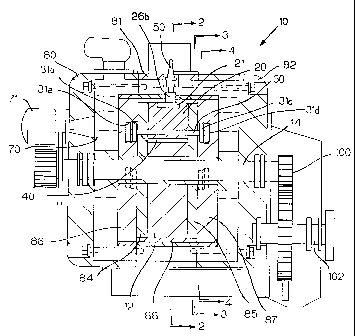
Figures 1-4 are various sectional views of a preferred intenlal conibustion
engine 10
made in accordance witli the present invention. The engine 10 is generally
coniprised of a torque
7
CA 02468169 2004-05-21
WO 03/060299 PCT/US03/00477
wheel 12 (also referred to as a balance wheel) mounted for rotation within a
housing and driving
a crankshaft 14. The housing generally comprises a front portion 80, a center
portion 81, and
rear portion 82. These portions 80, 81, 82 collectively define a central
cavity (or combustion
chamber) in which the torque wheel 12 and associated components of the engine
10 are enclosed,
as is ftirther described below. Although not essential to the present
invention, as illustrated in the
various Figures, the housing portions 80, 81, 82 are preferably secured
together by a plurality of
bolts or similar fasteners arrayed around the circumference of the housing.
In this preferred enibodiment, the torque wheel 12 includes three separate
arms in a
spaced arrangement about the center of the torque wheel 12, tliereby defining
three
corresponding volutnes between the respective arms. Positioned within these
volumes are
substantially identical combustion gates 20, 22, 24. Although not directly
secured to the torque
wheel 12, the shape of the combustion gates 20, 22, 24 causes them to be
tightly retained and
oriented relative to the torque wheel 10. Although there are three separate
arms and associated
combustion gates 20, 22, 24 in this particular embodiment, fewer or niore anns
and gates could
be incoiporated into the engine 10 of the present invention without departing
from the spirit and
scope of the present invention.
As best stiown in Figure 2, each combustion gate 20, 22, 24 is niounted for
rotation
within the volumes between the respective anns of the torque wheel about a
respective pivot pin
40, 42, 44, each such pivot pin passing tlirougli a respective first opening
20a, 22a, 24a defined
through each combustion gate 20, 22, 24. Referring back to Figure 1, it can be
seen that each
pivot pin 40, 42, 44 is received in corresponding apertures in the surface of
seal plates 84, 85. In
this regard, it can be appreciated that the torque wheel 10 and the combustion
gates 20, 22, 24
are enclosed within the seal plates 84, 85, essentially creating a unitary
body that rotates within a
8
CA 02468169 2004-05-21
WO 03/060299 PCT/US03/00477
circumferential sleeve 88. The seal plates 84, 85 and this sleeve 88, which is
preferably
constructed of cast iron, are contained within the central cavity collectively
defined by the front
portion 80, center portion 81, and rear portion 82 of the housing.
The preferred engine 10 also includes elliptical cam cutouts 16 which serve as
a track to
guide the movement of the combustion gates 20, 22, 24. Specifically, the
engine 10 includes
cam cutout plates 86, 87 positioned adjacent the seal plates 84, 85 on either
side of the torque
wheel 12 and within the central cavity collectively defined by the front
portion 80, center portion
81, and rear portion 82 of the housing. As best shown in Figure 4, an
elliptical cutout 16 is
defined in the cam cutout plate 87 which serves as a track to guide the
movement of the
combustion gates 20, 22, 24. In this regard, as best shown in Figure 3, there
are curved slots 85a,
85b, 85c defined through the seal plate 85 such that cam guide pins 30, 32, 34
associated with
the respective combustion gates 20, 22, 24 can pass through the seal plate 87
and be received in
the elliptical cutout 16. Of course, similar slots 84a, 84b, 84c (as shown in
Figure 10) are
defined througli the second seal plate 84 to provide access to an identical
elliptical cutout defined
in the other cam cutout plate 86.
Referring now to Figure 2, eacli combustion gate 20, 22, 24 also defines a
second
opening 20b, 22b, 24b therethrough. The cam guide pins 30, 32, 34 mentioned
above pass
through these openings 20b, 22b, 24b and are received in the elliptical
cutouts 16, such that the
pivoting of the combustion gates 20, 22, 24 is controlled by the elliptical
cutouts 16.
Specifically, because of the respective cam guide pins 30, 32, 34 and the
elliptical shape of the
cutouts 16, the combustion gates 20, 22, 24 are nioved in and out with respect
to the center of the
torque wheel 12, eacii combustion gate 20, 22, 24 pivoting about its
respective pivot pin 40, 42,
44.
9
CA 02468169 2004-05-21
WO 03/060299 PCT/US03/00477
Referring now to the simplified sectional views of Figures 5 and 6, in
operation, as with
other engines, a starter (not shown) is used to commence rotation of the
torque wheel 12. As the
torque wheel 12 rotates clockwise, air is drawn into the housing of the
combustion engine 10
through an intake 17, as indicated by arrow 17a, and into a portion of the
combustion chamber
generally indicated by reference nunieral 26a. At the same time, a fuel
injector 60 (as shown in
Figure 2) introduces fuel into the portion of the combustion chamber 26a. As
the torque wheel
12 continues its rotation, the fuel/air mixture is compressed by the outward
movement of the
combustion gate 22, as dictated by the elliptical cutouts 16.
The fuel/air mixture is then compressed and rotated until the combustion gate
has been
moved to its most outward position at the vertex of the elliptical cutout 16,
the position of
combustion gate 20 in Figure 5, where an outer portion of the combustion
chamber 26b is
defined in the wall of the housing of the engine 10. At this point, a spark
plug 50 is used to
ignite the fitel/air mixture, causing a rapid expansion of the resultatit
combttstion gases, thus
imparting a torque on the torque wheel 12 that causes continued rotation of
the torque wheel 12.
In this regard, it is preferred that a cavity 21 be defined in the extemal
surface of the combustion
gate 20. Sitnilar cavities (not shown) are also defined the respective
external surfaces of the
other combustion gates 22, 24. This cavity 21 serves as an inner combustion
chamber that is in
alignment with the aforementioned outer portion of the conibustion chamber 26b
when the spark
plug 50 fires. Such a cavity 21 is shaped to cooperate with the outer portion
of the combustion
chamber 26b, thus creating a split combustion chamber that ensures that
combustion efficiently
applies a clockwise torque on the torque wheel 12. As illustrateci in Figures
2 anci 5, this split
combustion chamber is substantially rectangular in nature, which
experimentation lias indicated
is optimal for controlling and directing the forces of conibustion for maximum
torque.
CA 02468169 2004-05-21
WO 03/060299 PCT/US03/00477
Furthenmore, in this preferred embodinient, the substantially rectangular
split combustion
chaniber has a ratio of length to width to height of 3:1:1, witll
approximately one-half of the
volume of the split combustion chamber being the volume of the cavity 21.
Nevertheless, a wide
range of dimensions may be possible without departing from the spirit and
scope of the present
invention.
With respect to the split combustion chamber, aside from its role in ensuring
that
combustion efficiently applies a clockwise torque on the torque wheel 12, it
is estimated that a
significant percentage of remaining emissions (i.e., combustion or exhaust
gases) in the outer
portion of the combustion chamber 26b are re-burned, improving efficiency and
reducing
emissions.
As the torque wheel 12 continties its clockwise rotation, the elliptical
cutouts 16 cause the
combustion gate to move inwardly toward the center of the torque wheel 12,
allowing the
combustion gases to expand without daniaging the engine, as illustrated by the
position of
combustion gate 24 in Figure 5. Finally, as the torque wheel 12 approaches the
portion of the
combustion cliamber indicated by reference nuniera126c, the elliptical cutouts
16 cause the
combustion gate 24 to move otttwardly again, forcing the combustion gases
through an exhaust
outlet 18. As rotation of the torque wheel 12 continues, the combustion gate
is then again moved
inwardly, to repeat the cycle, air being drawn into the portion of the
combustion chamber
indicated by reference numeral 26a.
Referring again to the sectional view of Figure 1, as the torque wheel 12
rotates, the
crankshaft 14 is similarly rotated. A reduction gearing arrangement 100 is
then used to reduce
and inipart rotation to an output shaft 102. As a further refinement, although
not sliown in the
11
CA 02468169 2004-05-21
WO 03/060299 PCT/US03/00477
Figures, an oil punip associated with the engine 10 niay also be powered by
appropriate gearing
to the reduction gearing arrangement 100.
As a further refinement to the preferred engine 10 of the present invention,
it is
contemplated and preferred that each of the cain gttide pins 30, 32, 34 be
provided with
respective bushings that are received in the elliptical cutouts 16. As shown
in Figure 1, each cam
guide pin 30 is provided with four bushings 31a, 31b, 31c, 31d which are
received in pairs in the
identical elliptical cutouts 16 defined in the cam cutout plates 85, 86.
Referring now to the sectional view of Figure 9, it can be seen that each
preferred
elliptical cutout 16 actually has a stair-step cross-section for receiving the
pairs of guide bushings
31c, 31d, 33c, 33d associated with the cani guide pins 30, 32. Referring
specifically to the cam
guide pin 30, by constructing the preferred elliptical cutout 16 with such a
stair-step cross-
section, one bushing 31 c abuts a lower side wall of the elliptical cutout 16
while the second
bushing 31 d abuts an upper side wall of the elliptical cutout 16. Thus,
although some tolerance
is provided for vertical movenient of the cam guicle pin 30 relative to the
elliptical cutout 16, the
stair-step construction of the elliptical cutout 16 xnd relationship with the
bushings 3 1 c, 31 d
prevents dramatic movements of the guide pin 3(>' which could impede optimal
performance of
the engine 10.
Reviewing the various sectional views of the preferred engine 10 of Figures 1-
4, it can be
seen that the engine 10 in this preferred enibodiment of the present invention
also includes
various auxiliary components that improve its operation and efficiency. For
exaniple, the engine
10 has an appropriate lubrication system. In this preferred embodiment, an oil
pump (not
shown), wliich may be powered by appropriate gearing to the reduction gearing
arrangement
100, supplies oil into the elliptical cutouts 16 defined in the respective
cani cutout plates 86, 87,
12
CA 02468169 2004-05-21
WO 03/060299 PCT/US03/00477
preferably into the top and sides of the cutouts 16. In this manner, supplied
oil is provicled to and
around each cam guide pin 30, 32, 34 and their respective btishings, which are
received in pairs
in the elliptical cutouts 16. Furthermore, although not shown in the Figures,
it is contemplated
and preferred that the cam guide pins 30, 32, 34 be provided with oil holes
that allow circulation
of oil through the cam guide pins 30, 32, 34.
From the elliptical cutouts 16, oil is drawn into the central cavity defined
by the housing
of the engine 10 through the curved slots in the respective seal plates 84, 85
which allow the cam
guide pins 30, 32, 34 to pass through the seal plate 84, 85. As an additional
refinement, it is
contemplated that additional slots be drilled through the respective seal
plates 84, 85 to allow for
oil flow to the central cavity. Once introduced into the central cavity, oil
flows about the torque
wheel 12. Furthermore, as shown in Figure 2, the preferred engine 10 includes
channels 72 that
allow oil to circulate under the respective combustion gates 20, 22, 24. The
combustion gates
20, 22, 24 are themselves provided with oil holes that allow for lubrication
of the respective
pivot pins 40, 42, 44.
Oil is preferably drained through drain tubes positioned on either side of
roller bearings
supporting the crankshaft 14. Furthermore, there are preferably drain tubes in
liquid
conimunication with the lower portions of the elliptical cutouts 16 defined in
the respective cam
cutout plates 86, 87. Lastly, a drain tube niay be provided into the central
cavity of the engine 10
through the sleeve 88 to allow for the drainage of oil that escape around the
combustion gates 20,
22, 24. Each of the above-described drain tubes delivers oil to an oil pan or
siniilar receptacle
for subsequent pumping and re-circulation into the engine 10.
13
CA 02468169 2004-05-21
WO 03/060299 PCT/US03/00477
Furtliennore, as shown in Figure 1, the preferred engine 10 includes a cooling
system
comprised of water cooling jackets 70 surrounding the central coniponents of
the engine 10 and
ati associated water pump 71 to supply the cooling jackets 70.
Finally, as mentioned above, the most pronounced disadvantage of a rotary
piston engine
is the difficulty in adequately sealing the enclosed spaces between the piston
and the wall of the
combttstion chamber. Therefore, sealing the enclosed volumes that are
manipulated by the
combustion gates 20, 22, 24 is also important to the present invention.
Referring now to Figure 10, the preferred engine 10 includes multiple seals,
which are
preferably constructed of a carbon cast alloy. Of course, other appropriate
materials, including
bronze, can be used to construct the seals without departing from the spirit
and scope of the
present invention.
First, as illustrated in Figttre 10, each of the seal plates 84, 85 has a
series of
interconnected slots defined in the surface thereof in a somewhat hexagonal
pattem about its
periphery. Received in these slots are elongated seals, labeled with
references numerals 121,
122, 123, 124, 125, 126 with respect to the seal plate 84, and 131, 132, 133,
134, 135, 136 with
respect to the seal plate 85. Although not shown in the Figures, it is
contemplated and preferred
that compression springs be positioned in the slots at spaced intervals (e.g.,
one inch intervals)
below the elongated seals 121, 122, 123, 124, 125, 126, 131, 132, 133, 134,
135, 136 to bias
them away froni the seal plates 84, 85 to maintain an appropriate seal between
the seal plates 84,
85 and the cam cutout plates 86, 87 when the engine is assembled.
Secondly, interposed between the distal ends of the elongated seals 121, 122,
123, 124,
125, 126, 131, 132, 133, 134, 135, 136 are star-shaped sealing niembers, each
indicated by
reference numeral 170, which serve to interconnect the elongated seals 121,
122, 123, 124, 125,
14
CA 02468169 2004-05-21
WO 03/060299 PCT/US03/00477
126, 131, 132, 133, 134, 135, 136 arrayed about the periphery of the
respective seal plates 84,
85, as is further described below with respect to Figure 12.
Thirdly, on the outer surface of each arm of the torque wheel 12, two parallel
slots are
defined for receiving elongated seals 140, 142, 144, 146, 148, 150. These
elongated seals 140,
142, 144, 146, 148, 150 are designed to seal the torque wheel 12 relative the
sleeve 88 (as shown
in Figures 1-4) in which it is rotating. As illustrated in Figure 10, it is
contemplated and
preferred that each of these elongated seals 140, 142, 144, 146, 148, 150
extend outwardly
beyond the sides of the torque wheel 12 such that the seals 140, 142, 144,
146, 148, 150 are also
interposed between the respective seal plates 84, 85 and the circumferential
sleeve 88. Although
not shown in the Figures, it is conteniplated and preferred that conipression
springs also be
positioned in the slots defined in the outer surface of each arm of the torque
wheel 12 at spaced
intervals below the elongated seals 140, 142, 144, 146, 148, 150 to bias them
away from torque
wheel 12 to inaintain an appropriate seal between the torque wlieel 12 and
circumferential sleeve
88 when the engine is assembled.
Lastly, Figures 11A and 11B are perspective views of one combustion gate 20,
illustrating the positioning and orientation of preferred seals. Specifically,
the combustion gate
has series of interconnected slots defined in the outward external surface
thereof. Received in
these interconnected slots are elongated seals 160, 162, 164, 166. Siniilar
seals are also installed
on each of the other combustion gates 22, 24. As with the various seals
described above,
20 although not shown in the Figures, it is contemplated and preferred that
compression springs also
be positioned in the slots defined in the surface of the combustion gates 20,
22, 24 at spaced
intervals below the seals to bias them away from the combustion gates 20, 22,
24 to maintain an
appropriate seal.
CA 02468169 2004-05-21
WO 03/060299 PCT/US03/00477
Figure 12 is an enlarged view of one of the star-shaped sealing members 170
which
serves to interconnect the elongateci seals arrayed about the periphery of the
respective seal
plates 84, 85 of the preferred engine of Figure 1. As shown, not only does the
star-shaped
sealing member 170 receive and interconnect elongated seals 124, 125, it also
receives and
interconnects the elongated seal 146 that extends outwardly beyond the side of
the torque wheel
12 when the engine 10 is assembled.
An internal combustion engine constructed in accordance with the above
specification
avoids the problems of common reciprocating niotion, piston-type engines and
those of rotary
combustion engines. Unlike a reciprocating motion, piston-type engine, minimal
fuel and air for
each combustion is needed since it is not necessary to force a piston a
substantial vertical
distance within a cylinder. Rather, since the torque wheel 12 has a
substantial mass and inertia, a
relatively small conibustion that acts on the peripliery of the spinning
torque wheel 12 is
sufficient to drive the torque wheel 12. In this regard, with respect to the
preferred embodiinent
of the engine 10 described above, for every two revolutions of the crankshaft,
there are six
relatively small, controlled explosions as opposed to the one large explosion
necessary to drive a
position within a cylinder.
Furthermore, when a piston-cylinder arrangement is used, an offset crankshaft
is
necessary for transfonning the energy from linear nlotion into rotational
motion, resulting in a
loss of efficiency. Similarly, a rotary piston engine requires an offset
crankshaft due to the
eccentric movement of the rotary piston within the combustion chamber. The
torque wheel 12 of
the preferred engine 10 of the present invention is directly secured to the
crankshaft 14 so there
is no transformation of energy. The crankshaft 14 rotates witli the torque
wheel 12. In this
16
CA 02468169 2004-05-21
WO 03/060299 PCT/US03/00477
regard, its is preferred that the engine 10 of the present invention be nin at
a constant rotational
speed (RPM) in conjunction with a transmission designed to control the output
speed.
It will be obvious to those skilled in the art that other modifications may be
made to the
invention as described herein without departing from the spirit and scope of
the present
invention.
17