Language selection

Search

Patent 2468284 Summary

Third-party information liability

Some of the information on this Web page has been provided by external sources. The Government of Canada is not responsible for the accuracy, reliability or currency of the information supplied by external sources. Users wishing to rely upon this information should consult directly with the source of the information. Content provided by external sources is not subject to official languages, privacy and accessibility requirements.

Claims and Abstract availability

Any discrepancies in the text and image of the Claims and Abstract are due to differing posting times. Text of the Claims and Abstract are posted:

  • At the time the application is open to public inspection;
  • At the time of issue of the patent (grant).
(12) Patent Application: (11) CA 2468284
(54) English Title: SPRING-LESS MONOTUBE SHOCK ABSORBER
(54) French Title: AMORTISSEUR MONOTUBE SANS RESSORT
Status: Deemed Abandoned and Beyond the Period of Reinstatement - Pending Response to Notice of Disregarded Communication
Bibliographic Data
(51) International Patent Classification (IPC):
  • B62D 55/112 (2006.01)
  • B60G 13/06 (2006.01)
  • F16F 09/00 (2006.01)
  • F16F 09/10 (2006.01)
(72) Inventors :
  • FAREWELL, RONALD WAYNE (Canada)
(73) Owners :
  • ARVINMERITOR TECHNOLOGY, LLC
(71) Applicants :
  • ARVINMERITOR TECHNOLOGY, LLC (United States of America)
(74) Agent: GOWLING WLG (CANADA) LLP
(74) Associate agent:
(45) Issued:
(22) Filed Date: 2004-05-25
(41) Open to Public Inspection: 2004-12-18
Availability of licence: N/A
Dedicated to the Public: N/A
(25) Language of filing: English

Patent Cooperation Treaty (PCT): No

(30) Application Priority Data:
Application No. Country/Territory Date
10/464,191 (United States of America) 2003-06-18

Abstracts

English Abstract


A damper assembly includes a damper chamber and a remote reservoir chamber.
The remote reservoir chamber includes a floating piston. The floating piston
moves
within a reservoir cavity to accommodate the additional fluid volume from a
shaft
during the compression strokes. The floating piston separates a fluid chamber
which
receives a hydraulic fluid from the damping chamber and a compressible fluid
chamber
which contains a compressible fluid. The compressible fluid provides a much
higher
compression ratio than conventional gas chambers and thereby operates as a
bias to
compress the fluid chamber and operate as a spring.


Claims

Note: Claims are shown in the official language in which they were submitted.

CLAIMS
1. A damper assembly comprising;
a first housing comprising a first chamber containing a hydraulic fluid
and a first piston secured to a rod extending from said first chamber;
a second housing comprising a second chamber and a third chamber
separated by a second piston, said second piston separating said hydraulic
fluid within
said second chamber from a compressible fluid within said third chamber; and
a fluid passage communicating hydraulic fluid between said first and
second chambers in response to movement of said first piston within said first
chamber.
2. The damper assembly as recited in claim 1, wherein said compressible
fluid comprises a compressible liquid.
3. The damper assembly as recited in claim 1, further comprising an air
bladder within said compressible fluid.
4. The damper assembly as recited in claim 1, wherein said compressible
fluid provides a compression ratio greater than 200 pounds.
5. The damper assembly as recited in claim 1, wherein said second housing
is located remote from said first housing.
6. The damper assembly as recited in claim 1, wherein said fluid passage
comprises a conduit.
-5-

7. A method of providing a rebound force for a monotube shock absorber
comprising the steps of:
(1) separating a hydraulic fluid from a compressible fluid within a
remote reservoir;
(2) compressing the compressible fluid in response to compression of
the monotube shock absorber; and
(3) extending the monotube shock absorber in response to
decompression of the compressible fluid within the reservoir.
8. A method as recited in claim 7, wherein said step (2) further comprises
compressing an air bladder within the compressible fluid.
-6-

Description

Note: Descriptions are shown in the official language in which they were submitted.


CA 02468284 2004-05-25
SPRING-LESS MONOTUBE SHOCK ABSORBER
BACKGROUND OF THE INVENTION
The present invention relates to a shock absorber with a remote reservoir
fluid
chamber, and more particularly to a monotube shock absorber with a remote
reservoir
fluid chamber which replaces a heretofore required coil spring.
Many conventional monotube shock absorbers include a reservoir chamber
having a quantity of fluid in communication with a main chamber of the shock
absorber.
The main chamber of the shock absorber includes a piston that divides the
chamber and
controls the fluid flow between sections of the chamber. The fluid reservoir
increases
or decreases the hydraulic fluid to the main chamber in response to movement
of the
piston within the main damper chamber.
The reservoir allows the main damper chamber to be, constructed shorter than
normally would be allowed and may allow the use of a larger shaft that
connects the
piston and damper assembly to one of the mounting members of the damper
assembly.
The shaft takes up volume within the damper assembly and the larger diameter
of the
shaft reduces the volume available for the storage of hydraulic fluid in the
main
chamber. For these reasons, it has been found desirable to provide remote
reservoir
chamber to separate additional fluid volume from the gas.
A coil spring or other biasing member is typically located about the shock
absorber to provide for rebound of the shock after a compression event.
Although
effective, the coil spring is a relatively expensive component or considerable
weight.
For some vehicle applications, such as snowmobile shock absorbers, such a
spring may
increase the unit cost of the shock absorber considerably.
Accordingly, it is desirable to provide a remote reservoir chamber for a
damper
assembly that eliminates the requirement for a spring.
SUMMARY OF THE INVENTION
The damper assembly of this invention includes a damper chamber and a remote
reservoir chamber. The remote reservoir chamber includes a floating piston.
The
floating piston moves within a reservoir cavity to accommodate the additional
volume
_1_

CA 02468284 2004-05-25
of the shaft during the compression and rebound strokes. The floating piston
separates a
fluid chamber which receives a hydraulic fluid from the damping chamber and a
compressible fluid chamber which contains a compressible fluid. The
compressible
fluid provides a much higher compression ratio than conventional gas chambers
and
S thereby operates as a bias to compress the fluid chamber and operate as a
spring.
An air bladder may be provided within the compressible fluid. The air bladder
reduces the volume of compressible fluid required to fill the compressible
fluid chamber.
Typically, a reduction of the air bladder will require a larger compressible
fluid chamber
to achieve the same compression ratio. The relative compression ratio provided
by the
compressible fluid may therefore be adjusted in relation to the relative
volume of
compressible fluid and the volume of the air bladder.
The present invention therefore provides a remote reservoir chamber for a
damper assembly that eliminates the requirement for a spring.
BRIEF DESCRIPTION OF THE DRAWINGS
The various features and advantages of this invention will become apparent to
those skilled in the art from the following detailed description of the
currently preferred
embodiment. The drawings that accompany the detailed description can be
briefly
described as follows:
Figure 1 is a schematic view of a snowmobile depicting a rear shock absorber
in
phantom; and
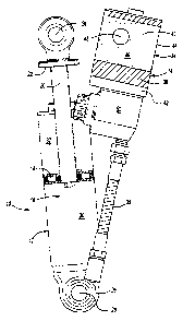
Figure 2 is a general partial sectional view of a monotube shock absorber.
DETAILED DESCRIPTION OF THE PREFERRED EMBODIMENT
Figure 1 illustrates a general perspective view of a damper assembly 10 for a
vehicle such as a snowmobile 11. The damper assembly 10 connects tracks 13 to
the
body of the snowmobile 11 by suspension linkages for damping inputs from the
roadway. The present invention adjustable shock absorber is desirable for
snowmobile
applications, and most desirable for rear shock absorbers for snowmobiles.
However, it
is to be understood that the adjustable shock absorber may be utilized for any
number of
other applications.
-2-

CA 02468284 2004-05-25
The damper assembly 10 includes a first housing 12 and a second housing 14.
The first housing 12 defines a damper chamber 16. The damper chamber 16
includes a
piston 18 attached to a shaft 20. The shaft 20 extends from the damper chamber
16 for
mounting of the damper assembly 10 through an end cap 22 having an aperture
24. The
opposite end of the housing 12 includes another end cap 26 with a mounting
aperture
28.
The piston 18 divides the chamber 16 into compression 30 and rebound 32
chambers.
The piston 18 moves within the chamber 16 dampening oscillations between two
suspension members connected to the end caps 22, 26 which are movable relative
to
each other. As appreciated, various mounting arrangements of the damper
assembly 10
will benefit from the instant invention.
The damper chamber 16 is in fluid communication with a remote reservoir
chamber 34 through a conduit 36 or the like. Conduit 36 is preferably a
flexible braided
steel hose or tubing, however, other fluid communication paths will also
benefit from
the present invention. The remote reservoir chamber 34 is defined by the
second
housing 14. The second housing 14 may be remotely located from the first
housing 12.
The remote reservoir chamber 34 includes a floating piston 38. The floating
piston 38 moves within a reservoir cavity 40 to accommodate the additional
volume of
the shaft 20 during the compression and rebound strokes. The floating piston
38 also
separates a fluid chamber 42 which receives a hydraulic fluid within the
damper
chamber 16 and a compressible fluid chamber 44 which contains a compressible
fluid
46. The compressible fluid is preferably an oil and air mixture. That is, the
oil contains
small beads of air, thus allowing for the compressibility. It should be
understood that
various compressible fluids will benefit from the instant invention. The
compressible
fluid 46 provides a much higher compression ratio than conventional gas
chambers and
thereby operates as a bias to compress the hydraulic fluid within the fluid
chamber 42.
An air bladder 48 is provided within the compressible fluid 46. The air
bladder
48 reduces the volume of compressible fluid 46 required to fill the
compressible fluid
chamber 44. The air volume inside the air bladder 48, combined with the total
volume
of all the air beads, is large enough to accept the total rod volume. Other
than these two
-3-

CA 02468284 2004-05-25
sources of air, the remainder of the oil in the shock is incompressible.
Without an air
bladder, 48 the compressible fluid itself would not contain enough air volume.
Typically, a reduction of the air bladder will require a larger compressible
fluid chamber
44 to achieve the same compression ratio. The relative compression ratio
provided by
the compressible fluid 46 may therefore be adjusted in relation to the
relative volume of
compressible fluid 46 and the volume of the air bladder 48. That is, the
overall
compression ratio and thus the spring force may be adjusted for particular
applications.
An adjustment member 50 may be located in fluid communication with the
remote reservoir chamber 34 to permit adjustment of the damping
characteristics of the
damper assembly 10, and in turn, adjustment of the ride handling
characteristics of the
snowmobile. The floating piston 38 responsiveness is preferably adjusted by
modifying
fluid flow between the damper chamber 16 and the fluid chamber 42 by varying
the
adjustment member 50 as generally known.
Through the elimination of the coil spring an extremely inexpensive and
compact shock absorber of reduced weight is thereby provided by the present
invention.
The foregoing description is exemplary rather than defined by the limitations
within. Many modifications and variations of the present invention are
possible in light
of the above teachings. The preferred embodiments of this invention have been
disclosed, however, one of ordinary skill in the art would recognize that
certain
modifications would come within the scope of this invention. It is, therefore,
to be
understood that within the scope of the appended claims, the invention may be
practiced
otherwise than as specifically described. For that reason the following claims
should be
studied to determine the true scope and content of this invention.
-4-

Representative Drawing
A single figure which represents the drawing illustrating the invention.
Administrative Status

2024-08-01:As part of the Next Generation Patents (NGP) transition, the Canadian Patents Database (CPD) now contains a more detailed Event History, which replicates the Event Log of our new back-office solution.

Please note that "Inactive:" events refers to events no longer in use in our new back-office solution.

For a clearer understanding of the status of the application/patent presented on this page, the site Disclaimer , as well as the definitions for Patent , Event History , Maintenance Fee  and Payment History  should be consulted.

Event History

Description Date
Application Not Reinstated by Deadline 2008-05-26
Time Limit for Reversal Expired 2008-05-26
Deemed Abandoned - Failure to Respond to Maintenance Fee Notice 2007-05-25
Inactive: IPC from MCD 2006-03-12
Application Published (Open to Public Inspection) 2004-12-18
Inactive: Cover page published 2004-12-17
Inactive: First IPC assigned 2004-08-05
Inactive: IPC assigned 2004-08-05
Application Received - Regular National 2004-06-25
Letter Sent 2004-06-25
Inactive: Filing certificate - No RFE (English) 2004-06-25
Correct Inventor Requirements Determined Compliant 2004-06-25

Abandonment History

Abandonment Date Reason Reinstatement Date
2007-05-25

Maintenance Fee

The last payment was received on 2006-04-27

Note : If the full payment has not been received on or before the date indicated, a further fee may be required which may be one of the following

  • the reinstatement fee;
  • the late payment fee; or
  • additional fee to reverse deemed expiry.

Patent fees are adjusted on the 1st of January every year. The amounts above are the current amounts if received by December 31 of the current year.
Please refer to the CIPO Patent Fees web page to see all current fee amounts.

Fee History

Fee Type Anniversary Year Due Date Paid Date
Application fee - standard 2004-05-25
Registration of a document 2004-05-25
MF (application, 2nd anniv.) - standard 02 2006-05-25 2006-04-27
Owners on Record

Note: Records showing the ownership history in alphabetical order.

Current Owners on Record
ARVINMERITOR TECHNOLOGY, LLC
Past Owners on Record
RONALD WAYNE FAREWELL
Past Owners that do not appear in the "Owners on Record" listing will appear in other documentation within the application.
Documents

To view selected files, please enter reCAPTCHA code :


To view images, click a link in the Document Description column. To download the documents, select one or more checkboxes in the first column and then click the "Download Selected in PDF format (Zip Archive)" or the "Download Selected as Single PDF" button.

List of published and non-published patent-specific documents on the CPD .

If you have any difficulty accessing content, you can call the Client Service Centre at 1-866-997-1936 or send them an e-mail at CIPO Client Service Centre.


Document
Description 
Date
(yyyy-mm-dd) 
Number of pages   Size of Image (KB) 
Abstract 2004-05-24 1 19
Description 2004-05-24 4 214
Claims 2004-05-24 2 44
Drawings 2004-05-24 2 44
Representative drawing 2004-11-18 1 11
Courtesy - Certificate of registration (related document(s)) 2004-06-24 1 105
Filing Certificate (English) 2004-06-24 1 158
Reminder of maintenance fee due 2006-01-25 1 110
Courtesy - Abandonment Letter (Maintenance Fee) 2007-07-22 1 174