Language selection

Search

Patent 2468356 Summary

Third-party information liability

Some of the information on this Web page has been provided by external sources. The Government of Canada is not responsible for the accuracy, reliability or currency of the information supplied by external sources. Users wishing to rely upon this information should consult directly with the source of the information. Content provided by external sources is not subject to official languages, privacy and accessibility requirements.

Claims and Abstract availability

Any discrepancies in the text and image of the Claims and Abstract are due to differing posting times. Text of the Claims and Abstract are posted:

  • At the time the application is open to public inspection;
  • At the time of issue of the patent (grant).
(12) Patent: (11) CA 2468356
(54) English Title: INTAGLIO PRINTING MACHINE
(54) French Title: MACHINE D'IMPRESSION A GRAVURE EN CREUX
Status: Expired and beyond the Period of Reversal
Bibliographic Data
(51) International Patent Classification (IPC):
  • B41F 9/00 (2006.01)
  • B41F 9/02 (2006.01)
  • B41F 13/00 (2006.01)
(72) Inventors :
  • KAHL, GEORG (Germany)
  • DUENNINGER, REINHOLD (Germany)
(73) Owners :
  • KBA-NOTASYS SA
(71) Applicants :
  • KBA-NOTASYS SA (Switzerland)
(74) Agent: AVENTUM IP LAW LLP
(74) Associate agent:
(45) Issued: 2010-08-24
(86) PCT Filing Date: 2002-10-22
(87) Open to Public Inspection: 2003-06-12
Examination requested: 2007-09-20
Availability of licence: N/A
Dedicated to the Public: N/A
(25) Language of filing: English

Patent Cooperation Treaty (PCT): Yes
(86) PCT Filing Number: PCT/DE2002/003977
(87) International Publication Number: WO 2003047862
(85) National Entry: 2004-05-26

(30) Application Priority Data:
Application No. Country/Territory Date
101 58 093.2 (Germany) 2001-11-27

Abstracts

English Abstract


The invention relates to a printing machine by intaglio engraving comprising a
rack (01; 11; 14) with a stationary part (01) and a moving part (11; 14). A
plate cylinder (07) is rotationally mounted inside the stationary part, and an
Orlof-type cylinder (12) is mounted inside the moving part. The moving part is
mounted on a rail (04) in a suspended manner.


French Abstract

L'invention concerne une machine d'impression à gravure en creux comprenant un bâti (01 ; 11 ; 14) qui présente une partie fixe (01) et une partie mobile (11 ; 14). Un cylindre porte-plaque (07) est monté rotatif dans le partie fixe ; un cylindre de type Orlof (12) est monté dans la partie mobile. Ladite partie mobile est montée suspendue à un rail (04).

Claims

Note: Claims are shown in the official language in which they were submitted.

-7-
Claims
1. An intaglio printing machine comprising a rack (O1,
11, 14) in which there are rotatably mounted an Orlof-type
cylinder (12), a plate cylinder (07) and at least one gravure
cylinder (13), the rack (01, 11, 14) comprising a stationary
part (01), which bears the plate cylinder (07), and a first
moving part (11) that can be moved with respect to the
stationary part (01) and bears the Orlof cylinder (12),
characterized in that the first moving part (11) and the
second moving part (14) are arranged on a rail (04) in a
suspended manner, with an inking unit (16) of the at least one
gravure cylinder (13) being mounted in a second moving part
(14) of the rack.
2. The intaglio printing machine as claimed in claim 1,
characterized in that the at least one gravure cylinder (13)
is mounted in the first moving part (11).
3. The intaglio printing machine as claimed in claim 1,
characterized in that during operation of the intaglio
printing machine the parts (01; 11; 14) of the rack are
arrested.
4. The intaglio printing machine as claimed in claim 1,
characterized in that the stationary part (01) and an upright
(03) support the rail (04) and in that in a maintenance
position the second moving part (14) is arranged at a slight
distance from the upright (03).
5. The intaglio printing machine as claimed in claim 1,
characterized in that at least one dedicated actuator is
assigned to each moving part (11; 14).
6. The intaglio printing machine as claimed in claim 1,
characterized in that the first part (11) moves and the second
part (14) is stationary.

Description

Note: Descriptions are shown in the official language in which they were submitted.


CA 02468356 2004-05-26
1159P25CA01
- 1 -
Intaglio printing machine
The invention relates to an intaglio printing machine as
claimed in the preamble of claim 1.
Such a machine is known, for example, from EP 08 73 866
B1. This known printing machine has four gravure cylinders
which are in each case supplied with ink from an associated
inking unit. The surface of the gravure cylinder only receives
ink at local depressions or countersunk spots. This ink is
transferred to the ink-collecting cylinder which rotates in
contact with all gravure cylinders. There is thus a layer of
ink on the ink-collecting cylinder which may be made up of
contributions from various gravure cylinders and may have a
composition and coloring that varies from point to point. The
plates of a plate cylinder that rotates in contact with the
Orlof-type cylinder are colored by means of this layer of ink
of varying composition, and the image on the plates is printed
onto a printable material with a color distribution that is
defined by the composition of the layer of ink, said printable
material passing between the plate cylinder and a counter-
pressure cylinder. A multicolored image which is inherently
free of registration errors, since only a single printing
plate is used, is thus printed onto the printable material
with a single pass through the nip. This method is therefore
preferably used to print papers of value such as, for example,
bank notes.
Since the patterns of the depressions on the gravure
cylinders are specific for each individual application of ink,
it was important in older printing machines of this type for
the gravure cylinders to be easily dismountable. The
development of gravure printing plates has made it possible to
no longer have to dismount the gravure cylinders. However,
when this dismounting capability is omitted, in an intaglio
printing machine of the conventional type known from EP 08 73
866 B1 the accessibility to the Orlof-type cylinder is highly

CA 02468356 2004-05-26
- 2 -
restricted, and this makes cleaning thereof, for example,
considerably more difficult.
DE 690 08 941 T1 discloses an intaglio printing machine
for printing papers of value. In said document, plate and
pressure cylinders are arranged in a stationary main rack, the
ink-collecting cylinder and the ink selection roll are
arranged in a first moving rack and the inking units are
arranged in a second moving rack.
The object of the invention is to provide an intaglio
printing machine.
According to the invention, this object is achieved by
the features of claim 1.
The advantages that can be obtained by the invention are
in particular that the Orlof-type cylinder is easily
accessible for maintenance purposes without it being necessary
to dismount a gravure cylinder. Instead, the printing machine
may be provided with an interspace which ensures easy access
to the Orlof-type cylinder by moving the Orlof-type cylinder
away from the plate cylinder.
Since the first moving part of the rack, which bears the
Orlof-type cylinder and expediently also the gravure
cylinders, is arranged on a rail in a suspended manner, there
is no need to fix or make corresponding rails in a complex
manner on the floor of a hall or the like where the intaglio
printing machine is set up.
A second moving part of the rack may be provided as a
carrier for the inking unit of the gravure cylinder. By moving
this second moving part away from the first moving part an
interspace may also be created between inking unit and gravure
cylinder, via which interspace it is easy for operating
personnel to reach and clean the inking unit and the gravure
cylinder and to easily exchange gravure printing plates.

CA 02468356 2004-05-26
- 3 -
One example of embodiment of the invention is shown in
the drawings and described in more detail below.
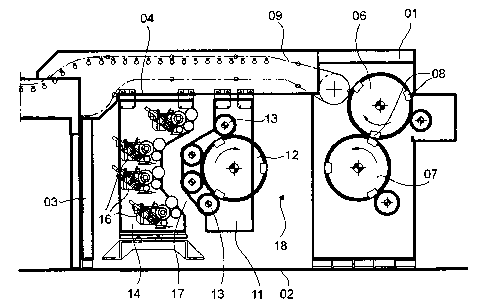
Fig. 1 shows a schematic longitudinal section through an
intaglio printing machine in an operating position.
Fig. 2 shows a similar section through the intaglio
printing machine in a cleaning and maintenance position.
The rack of the machine shown in Fig. 1 is composed of a
number of parts which in each case have two parallel, rigidly
connected plates. A first stationary part O1 is fixed to the
floor 02 of a hall or the like; its two plates, together with
uprights 03 that are likewise supported on the floor of the
hall, bear two parallel rails 04.
A counter-pressure cylinder 06 and a plate cylinder 07
are suspended rotatably in the stationary part O1. The
direction of rotation thereof is indicated by arrows. The
counter-pressure cylinder 06 is equipped with a number of
grippers 08 which grip sheets that are fed in from the right
in Fig. 1 in a manner that is not shown in any more detail,
pass them through a nip between plate cylinder 07 and counter-
pressure cylinder 06, where they are printed, and then
transfer them to a gripper chain arrangement 09 from which
they are passed via the rail 04 to an extension arm that is
not shown in Fig. 1.
A first moving part 11 of the rack is suspended on the
rails 04. The first moving part 11 bears an Orlof-type
cylinder 12, that is to say a collecting cylinder, and a
number of, in this case four, gravure cylinders 13 which
rotate in contact with the Orlof-type cylinder 12.
A second moving part 14 of the rack, which is likewise
suspended on the rails 04, bears four inking units 16, each of

CA 02468356 2004-05-26
- 4 -
which in the position shown supplies ink to one of the gravure
cylinders 13.
During operation of the printing machine, the rack parts
O1; 11; 14 are arrested with respect to one another in the
position shown in Fig. 1.
In order to be able to exchange the gravure printing
plates on the gravure cylinders 13 for a new application of
ink, the second moving part 14 can be moved out of its
position shown as a continuous outline in Fig. 2 along the
rail 04 into a maintenance position in which the second moving
part 14 is shown as a dashed outline in Fig. 1. In this
position, the second moving part 14 is only at a slight
distance (e.g. less than 50 cm) from the upright 03, and an
operating person can enter a passageway 17 (wider than 60 cm)
that has been made between the second moving part 14 and the
first moving part 11 in order to carry out maintenance work on
the inking units and the gravure cylinders 13.
In order also to be able to clean the Orlof-type cylinder
12 in a convenient manner without having to dismount the
gravure cylinders 13, the first moving part 11 can likewise be
moved in the direction of the upright 03, as shown in Fig. 2.
While during displacement of the first moving part 11 a new
passageway 18 (wider than 60 cm) opens up between the first
moving part 11 and the stationary part O1 of the rack, the
passageway 17 (smaller than 40 cm, in particular smaller than
30 cm) closes. The space requirement of the printing machine
is therefore no greater than in the case of the printing
machine according to EP 08 73 866 B1 which has already been
cited; however, the access and maintenance possibilities are
considerably improved.
The movement of the first part 11 and of the second part
14 takes place in each case by means of at least one dedicated
actuator, e.g. an electric motor or pressure-activated working
cylinder. The first part 11 and the second part 14 may be

CA 02468356 2004-05-26
- 5 -
moved independently of one another. Thus the first part 11 is
moved, for example, while the second part 14 remains
stationary in its maintenance position.
Preferably, two actuators that are synchronized with one
another are provided for each part 11, 14.

CA 02468356 2004-05-26
- 6 -
List of references
O1 part, stationary
02 floor
03 upright
04 rail
05 -
06 counter-pressure cylinder
07 plate cylinder
08 gripper
09 gripper chain arrangement
-
11 part, first, moving
12 Orlof-type cylinder
13 gravure cylinder
14 part, second, moving
-
16 inking unit
17 passageway
18 passageway

Representative Drawing
A single figure which represents the drawing illustrating the invention.
Administrative Status

2024-08-01:As part of the Next Generation Patents (NGP) transition, the Canadian Patents Database (CPD) now contains a more detailed Event History, which replicates the Event Log of our new back-office solution.

Please note that "Inactive:" events refers to events no longer in use in our new back-office solution.

For a clearer understanding of the status of the application/patent presented on this page, the site Disclaimer , as well as the definitions for Patent , Event History , Maintenance Fee  and Payment History  should be consulted.

Event History

Description Date
Time Limit for Reversal Expired 2022-04-22
Letter Sent 2021-10-22
Letter Sent 2021-04-22
Letter Sent 2020-10-22
Common Representative Appointed 2019-10-30
Revocation of Agent Request 2018-06-06
Appointment of Agent Request 2018-06-06
Revocation of Agent Requirements Determined Compliant 2018-05-18
Appointment of Agent Requirements Determined Compliant 2018-05-18
Maintenance Request Received 2016-08-31
Letter Sent 2011-10-26
Grant by Issuance 2010-08-24
Inactive: Cover page published 2010-08-23
Pre-grant 2010-06-15
Inactive: Final fee received 2010-06-15
Notice of Allowance is Issued 2010-02-24
Letter Sent 2010-02-24
Notice of Allowance is Issued 2010-02-24
Inactive: Approved for allowance (AFA) 2010-02-18
Amendment Received - Voluntary Amendment 2009-07-28
Inactive: Delete abandonment 2009-01-28
Inactive: Office letter 2009-01-28
Inactive: S.30(2) Rules - Examiner requisition 2009-01-28
Inactive: Adhoc Request Documented 2009-01-28
Inactive: Abandoned - No reply to Office letter 2008-09-26
Amendment Received - Voluntary Amendment 2008-07-22
Inactive: Correction to amendment 2008-06-26
Amendment Received - Voluntary Amendment 2008-04-22
Letter Sent 2007-10-17
All Requirements for Examination Determined Compliant 2007-09-20
Request for Examination Requirements Determined Compliant 2007-09-20
Request for Examination Received 2007-09-20
Letter Sent 2005-03-10
Inactive: Single transfer 2004-12-14
Inactive: Courtesy letter - Evidence 2004-08-17
Inactive: Cover page published 2004-08-12
Inactive: Notice - National entry - No RFE 2004-08-09
Inactive: First IPC assigned 2004-08-05
Application Received - PCT 2004-06-28
National Entry Requirements Determined Compliant 2004-05-26
Application Published (Open to Public Inspection) 2003-06-12

Abandonment History

There is no abandonment history.

Maintenance Fee

The last payment was received on 2009-09-25

Note : If the full payment has not been received on or before the date indicated, a further fee may be required which may be one of the following

  • the reinstatement fee;
  • the late payment fee; or
  • additional fee to reverse deemed expiry.

Please refer to the CIPO Patent Fees web page to see all current fee amounts.

Owners on Record

Note: Records showing the ownership history in alphabetical order.

Current Owners on Record
KBA-NOTASYS SA
Past Owners on Record
GEORG KAHL
REINHOLD DUENNINGER
Past Owners that do not appear in the "Owners on Record" listing will appear in other documentation within the application.
Documents

To view selected files, please enter reCAPTCHA code :


To view images, click a link in the Document Description column. To download the documents, select one or more checkboxes in the first column and then click the "Download Selected in PDF format (Zip Archive)" or the "Download Selected as Single PDF" button.

List of published and non-published patent-specific documents on the CPD .

If you have any difficulty accessing content, you can call the Client Service Centre at 1-866-997-1936 or send them an e-mail at CIPO Client Service Centre.


Document
Description 
Date
(yyyy-mm-dd) 
Number of pages   Size of Image (KB) 
Description 2004-05-26 6 210
Abstract 2004-05-26 2 78
Drawings 2004-05-26 1 34
Claims 2004-05-26 1 41
Representative drawing 2004-05-26 1 15
Cover Page 2004-08-12 1 41
Description 2008-07-22 6 190
Claims 2008-04-22 2 65
Description 2009-07-28 7 216
Claims 2009-07-28 2 63
Representative drawing 2010-07-28 1 14
Cover Page 2010-07-28 1 41
Notice of National Entry 2004-08-09 1 193
Courtesy - Certificate of registration (related document(s)) 2005-03-10 1 105
Reminder - Request for Examination 2007-06-26 1 118
Acknowledgement of Request for Examination 2007-10-17 1 177
Commissioner's Notice - Application Found Allowable 2010-02-24 1 165
Commissioner's Notice - Maintenance Fee for a Patent Not Paid 2020-12-10 1 544
Courtesy - Patent Term Deemed Expired 2021-05-13 1 540
Commissioner's Notice - Maintenance Fee for a Patent Not Paid 2021-12-03 1 553
PCT 2004-05-26 8 275
Correspondence 2004-08-09 1 26
Fees 2005-10-20 1 56
Correspondence 2008-06-26 1 16
Correspondence 2009-01-28 1 11
Correspondence 2010-06-15 2 61
Maintenance fee payment 2016-08-31 1 26