Note: Descriptions are shown in the official language in which they were submitted.
CA 02468512 2004-05-27
WO 03/049781 PCT/US02/39054
IN-SITU OXIDIZED TEXTURED SURFACES FOR PROSTHETIC DEVICES AND
METHOD OF MAKJNG SAME
CROSS-REFERENCE TO RELATED APPLICATIONS
[0001] This application claims benefit of and priority to U.S. provisional
patent
application Ser. No. 60/338,420, filed December 6, 2001.
TECHNICAL FIELD
[0002] The present invention relates generally to the field of orthopedic
implants.
Specifically, it is directed to orthopedic implants having texture-modified
surfaces coated
with a thin, dense, highly wear-resistant coating of diffusion hardened
oxidation layer.
Preferably, the texture modification is effected through chemical or
electrochemical etching
and the metallic implant comprises zirconium and the surface layer comprises
oxidized
zirconium. The surface coatings have an enhanced ability to promote bone in-
growth. This
invention also relates to methods for producing metallic orthopedic implants
having texture-
modified surfaces.
BACKGROUND OF THE INVENTION
[0003] Orthopedic implant materials must combine high strength, corrosion
resistance and tissue compatibility. The longevity of the implant is of prime
importance
especially if the recipient of the implant is relatively young because it is
desirable that the
implant function for the complete lifetime of a patient. Because certain metal
alloys have the
required mechaiucal strength and biocompatibility, they are ideal candidates
for the
fabrication of prostheses. These alloys include 316L stainless steel, chrome-
cobalt-
molybdenum alloys and, more recently, titanium alloys which have proven to be
the most
suitable materials for the fabrication of load-bearing prostheses.
[0004] It has also been found that metal prostheses are not completely inert
in the
body. Body fluids act upon the metals causing them to slowly corrode by an
ionizing process
that thereby releases metal ions into the body. Metal ion release from the
prosthesis is also
related to the rate of wear of load bearing surfaces because the passive oxide
film, which is
formed on the surface, is constantly removed: The repassivation process
constantly releases
metal ions during the ionizing process. Furthermore, the presence of third-
body wear
-1-
CA 02468512 2004-05-27
WO 03/049781 PCT/US02/39054
(cement or bone debris) accelerates this process and microfretted metal
particles increase
friction.
[0005] The excellent corrosion resistance of zirconium has been known for many
years. Zirconium displays excellent corrosion resistance in many aqueous and
non-aqueous
media and for this reason has seen an increased use in the chemical process
industry and in
medical applications. A limitation to the wide application of zirconium in
these areas is its
relatively low resistance to abrasion and its tendency to gall. This
relatively low resistance to
abrasion and the tendency to gall is also demonstrated in zirconium alloys.
[0006] U.S. Patent 2,987,352 to Watson first disclosed a method of producing
zirconium bearings with a specific form of oxidized zirconium as a surface
layer. The
method of Watson was refined by Haygarth (U.S. Patent 4,671,824) resulting in
improved
abrasion resistance and better dimensional control of the oxidized product.
The U.S. Patents
of Davidson (5,037,438; 5,152,794; 5,180,394; 5,370,694; 5,372,660; 5,496,359;
and
5,549,667) demonstrated the many advantages that are realized through the use
of the specific
form of oxidized zirconium on zirconium and zirconium alloy substrates in
prosthetic
devices. These include increased strength, low friction and high wear
resistance. U.S. Patent
5,037,438 to Davidson first disclosed a method of producing zirconium alloy
prostheses with
un oxidized zirconium surface. The work of Watson and Davidson teach a
specific form of
oxidized zirconium which possesses all of the advantages of ceramic materials
while
maintaining the strength of metallic surfaces. The oxidation is characterized
by the diffusion
of free oxygen into the surface of the metal; the resulting oxide layer is
characterized by the
diffusion of free oxygen into the surface of the metal. The resulting
"diffusion hardened"
materials possess a unique combination of the advantageous properties of a
ceramic and a
metal, simultaneously minimizing the disadvantages of these materials. All of
the U.S.
Patents cited above to Davidson, Watson, and Haygarth are incorporated by
reference as
though fully set forth herein. While the early work of Davidson focused on
pure zirconium
and alloys of zirconium in which zirconium was the predominant metal, later
work has shown
that this is not necessary in order to form the desired diffusion hardened
oxide. For instance,
an alloy of 74 wt% titanium, 13 wt% niobium and 13 wt% zirconium ("Ti-13-13")
will form
the diffusion hardened oxidation layer used herein. Ti-13-13 is taught in U.S.
Patent
x,169,567 to Davidson et al.
[0007] Another important performance criterion for medical implants is the
degree of fixation stability. This is typically accomplished tluough ingrowth
of surrounding
tissue into the implant and its ability to become firmly anchored to other
components such as
-2-
CA 02468512 2004-05-27
WO 03/049781 PCT/US02/39054
bone cement with a large shear strength. A typical hip joint prosthesis
includes a stem
fixated into the femur, a femoral head, and an acetabular cup against which
the femoral head
articulates. A typical knee joint prosthesis has a femoral and tibial
component, both of which
are fixated to the respective bones. This is the stability with which the
implant is anchored in
place. This fixation could be to either bone or other tissue, or may consist,
at least in part of
materials, such as bone cement, etc. The fixation stability of the prostheses
of Davidson was
realized in their use of porous metal beads or wire mesh coatings the promoted
bone in-
growth and increased surface area for adhesion to other materials. These
techniques are
vaught in U.S. Patent 5,037,438 and other patents of Davidson, and when
combined with the
advantages of oxidized zirconium, represented an improvement in performance of
medical
implants in numerous areas. Nevertheless, continued improvement in the
fixation stability of
such implants is desirable.
[0008] A principle goal in the field of prosthetic implants is the lengthening
of the
useful life of the implant such as to avoid or minimize the need for surgical
revision or
replacement. A delay or complete prevention of failure of an implant is
desirable. The
causes of implant failure are numerous. It is believed that the failures are
attributable to the
body°s rejection of bone cement. It is also believed that rejection of
bone cement is not the
primary problem, but rather that bone cement is not a proper structural
component for use as
part of a joint implant because of its physical properties.
[0009] Specifically, natural bone has a modulus of elasticity of up to about
4x10⁶
p.s.i. The metals used for implants generally have a modulus of elasticity on
the order of 15-.
35x106 p.s.i. Polymethylmethacrylate (PMMA) cement, on the other hand, has a
modulus of
elasticity on the order of 0.3-0.5x10⁶ p.s.i. The stiffiiess of PMMA cement is
therefore less
than either the metal prosthesis or the surrounding bone. Cement has lower
mechanical
properties strength and fatigue strength properties than does metal or bone.
These
comparative physical properties are thought to be the source of failure of hip
and knee
prostheses implanted using bone cement.
[0010] Prostheses may also be implanted without cement. These devices achieve
fixation by in-growth of bone or tissue into the prosthesis or by wedging the
prosthesis into
bone. The devices may also include surface features which enhance ingrowth
with fibrous
tissue or bone. The surface features may be applied by deposition or spraying
techniques.
[0011] It is generally understood that surface roughening results in increased
surface area which typically leads to better adhesion for the fixation of two
surfaces.
Although a smooth surface minimizes the stresses within the implant, it also
minimizes the
-3-
CA 02468512 2004-05-27
WO 03/049781 PCT/US02/39054
total surface area. This decreased surface area significantly reduces the
strength of the
attaclunent of the implant to the bone and tissue, which is largely dependent
upon the
mechanical interaction of the implant and the tissue. This mechanical
interaction is of two
forms. One is a form of interlocking to the extent the tissue grows behind or
around a part of
the implant. The other is frictional, wherein the tissue grows into intimate
approximation with
the surface and results in a relatively tight frictional fit.
[0012] Wagner et al. have demonstrated a method in U.S. Patent 5,922,029 (and
the resulting product in U.S. Patent 6,193,762) using an electrochemical
etching techniques to
create attachment surfaces having random irregular patterns that promote bone
tissue
ingrowth and also to facilitate joining of the surface to a second material.
Wagner et al. teach
analogous methods (U.S. Patent 5,258,098) and medical implant products (U.S.
Patent
5,507,815) in which the etching methodology used is purely chemical. Although
the
+echniques of Wagner et al. represent one potential source of methods for
surface texture
modification it is expected that any other surface texture modification
techniques would be
similarly useful in aiding fixation. For example, the teachings of Frey (U.S.
Patent
4,272,855), Van Kampen (U.S. Patent 4,673,409, Sump (IJ.S. Patent 4,644,942),
and Noiles
(U.S. Patent 4,865,603), among others, can be combined with iyz situ diffusion
hardened
surface oxidation of Davidson to' produce a prosthesis surface having the
superior attributes
of surface oxidation as well as the stabilization and in-growth enhancement
benefits accruing
from macroscopic texture modification.
[0013] There exists a need for a method to produce medical implants having
improved fixation while preserving or improving the advancements realized
through the use
of oxidized zirconium. This improved stability is needed both with respect to
the interface
between the implant and bone and surrounding tissue as well as in the
interface between the
implant and other material such as bone cement. This should be accomplished
while
simultaneously preserving the advantages which inure through the use of i~a
situ oxidized,
diffusion hardened surfaces such as oxidized zirconium.
SUM1VIAR~ OF THE INVENTION
[0014] The invention is directed to a textured surface and oxidation layer
coating
on a substrate material and prosthetic devices of such textured surfaces and
oxidation layer
coatings.
-4-
CA 02468512 2004-05-27
WO 03/049781 PCT/US02/39054
[0015] In one aspect of the present invention, there is a method of producing
a
modified surface on a metallic substrate comprising the steps of modifying the
texture of at
least a portion of the surface of said metallic substrate, and oxidizing at
least a portion of the
surface of said metallic substrate to form a diffusion hardened surface on
said metallic
substrate.
[0016] The following are specific embodiments of the method invention which,
when used, may be used alone or in combination with other embodiments.
[0017] W other method embodiments, the step of modifying may be characterized
by a chemical or electrochemical etching. The etching may be characterized by
etching with
acid. The etching may be characterized by the further step of applying a
maskant to the
surface of the metallic substrate. The maskant may be randomly applied. The
maskant may
be applied by spraying or sputtering onto said surface of said metallic
substrate. Such
spraying or sputtering may be characterized by a random application of
maskant. The
maskant may be applied to the surface of the metallic substrate by fully
covering the surface
with the maskant and thereafter partially removing a portion of the maskant.
The step of
partially removing the maskant may be characterized by the step of laser
ablating a portion of
said maskant.
[0018] In other method embodiments, the step of partially removing the maskant
may be characterized by the step of mechanically removing a portion of the
maskant. The
surface may be modified by mechanical etching. The surface may be modified by
deposition
of material onto the surface. The deposition may be characterized by chemical
vapor
deposition.
[0019] In other method embodiments, the step of oxidizing at least a portion
of
the surface of the metallic substrate may be characterized by air, steam, or
water oxidation
processes. The step of oxidizing at least a portion of the surface of the
metallic substrate may
be characterized by the use of oxygen as an oxidant. Alternatively, the
oxidation method
comprises the use of a salt bath.
[0020] In another embodiment, the metallic surface is zirconium or a zirconium
alloy. In a specific embodiment of the method, the zirconium alloy is selected
from the
group consisting of zirconium with up to about 4.5 percent by weight hafiiium
and up to
about 3.0 percent by weight niobium; zirconium with up to about 4.5 percent by
weight
hafnium; zirconium with 2.5 to 2.8 percent by weight niobium; and; titanium
with about 13
percent by weight niobium and about 13 percent by weight zirconium.
-s-
CA 02468512 2004-05-27
WO 03/049781 PCT/US02/39054
[0021] The metallic surface may comprise a metal selected from the group
consisting of hafnium, niobium, tantalum, and titanium.
[0022] In another embodiment of the present invention, there is a prosthesis
for
implantation comprising a first prosthesis portion and a second prosthesis
portion; said~first
prosthesis portion comprising a bearing surface, said bearing surface being
sized and shaped
to engage or cooperate with a second bearing surface on said second prosthesis
portion; and
wherein at least a portion of the surface of said first prosthesis portion or
said second
prosthesis portion or both is texture-modified by the process of any of
methods described
above, and wherein at least a portion of said first prosthesis portion or said
second prosthesis
portion or both comprises a diffusion hardened oxidation layer.
[0023] The following are specific embodiments of the prosthesis invention
which,
when used, may be used alone or in combination with other embodiments.
[0024] In other embodiments of the prosthesis, the first prosthesis portion is
a
femoral component fixrther characterized by having a bearing surface
comprising at least one
condyle and the second prosthesis portion is a tibial component further
characterized by a
tibial base, said tibial component adapted to cooperate with the bearing
surface. The tibial
component may comprise organic polymer or polymer based composite. The
metallic
prosthesis body may comprise zirconum or zirconium alloy and the diffusion
hardened
oxidation layer may be a blue-black or black oxidized zirconium coating. The
diffusion
hardened oxidation layer may have a thickness of up to about 20 microns. In
another
embodiment, the diffusion hardened oxidation layer may have a thickness of up
to about 10
microns.
[0025] In another embodiment of the prosthesis the first prosthesis portion is
further characterized by a femoral component having a head portion and a
bearing surface on
the head portion, and wherein the second prosthesis portion is further
characterized by an
acetabular cup having an imier surface adapted to cooperate with the bearing
surface on the
head portion. The inner surface may comprise an organic polymer or a polymer-
based
composite. The metallic prosthesis body may comprise zirconium or zirconium
alloy and the
diffusion hardened oxidation layer may be a blue-black or black oxidized
zirconium coating.
The diffusion hardened oxidation layer may have a thickness of up to about 20
microns. In
another embodiment, the diffusion hardened oxidation layer may have a
thickness of up to
about 10 microns. In a specific embodiment, the prosthesis is a spinal
prosthesis. Preferably,
the spinal prosthesis comprises zirconium or zirconium alloy and the diffusion
hardened
oxidation layer is a blue-black or black oxidized zirconium layer. In another
specific
-G-
CA 02468512 2004-05-27
WO 03/049781 PCT/US02/39054
embodiment, the spinal prosthesis is a spinal disc prosthesis. Preferably, the
spinal disc
prosthesis comprises zirconium or zirconium alloy and the diffusion hardened
oxidation layer
is a blue-black or black oxidized zircouum layer.
[0026] In another embodiment of the present invention, there is a medical
implant
for inserting into the body tissue of the patient, the implant comprising a
component, wherein
at least a portion of the surface~of the component is texture-modified by the
process of any of
methods described above, and further wherein at least a portion of the surface
of the
component comprises a diffusion hardened oxidation layer.
[0027] The medical implant invention has a number of specific embodiments
which, when used, may be used alone or in combination with other embodiments.
The
medical implant may be a bone plate or a bone screw. The metallic prosthesis
body may
comprise zirconium or zirconium alloy and the diffusion hardened oxidation
layer may be a
blue-black or black oxidized zirconium coating. The diffusion hardened
oxidation layer may
have a thickness of up to about 20 microns. The diffusion hardened oxidation
layer may have
a thickness of up to about 10 microns. The medical implant may further
comprising a self
grafting device.
[0028] The foregoing has outlined rather broadly the features and technical
advantages of the present invention in order that the detailed description of
the invention that
follows may be better understood. Additional features and advantages of the
invention will
be described hereinafter which form the subject of the claims of the
invention. It should be
appreciated by those skilled in the art that the conception and specific
embodiment disclosed
may be readily utilized as a basis for modifying or designing other structures
for carrying out
the same purposes of the present invention. It should also be realized by
those skilled in the
art that such equivalent constructions do not depart from the spirit and scope
of the invention
as set forth in the appended claims. The novel features which are
characteristic of the
invention, both as to its organization and method of operation, together with
further objects
and advantages will be better understood from the following description when
considered in
connection with the accompanying figures. It is to be expressly understood,
however, that
each of the figures is provided for the purpose of illustration and
description only and is not
intended as a definition of the limits of the present invention.
DESCRIPTION OF THE DRAWINGS
[0029] Figure 1 is a schematic diagram depicting a hip joint prosthesis in
position.
_7_
CA 02468512 2004-05-27
WO 03/049781 PCT/US02/39054
[0030] Figure 2 is a schematic diagram showing a typical hip join prosthesis.
[0031] Figure 3 is a schematic diagram of a knee joint prosthesis in place.
[0032] Figure 4 is a schematic diagram of the parts of a typical lcnee joint.
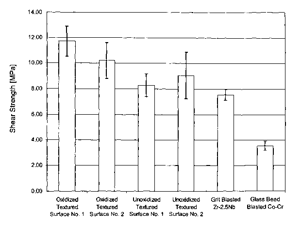
[0033] Figure 5 is a bar graph, including error bars, of the Shear Strength of
various surfaces.
[0034] Figure 6 graphically shows the results of pin push-out testing for
various
surfaces.
DETAILED DESCRIPTION OF THE INVENTION
[0035] As used herein, "a" or "an" may mean one or more. As used herein in the
claim(s), when used in conjunction with the word "comprising", the words "a"
or "an" may
mean one or more than one. As used herein, "another" may mean at least a
second or more.
[0036] As used herein, the term, "medical implant" includes any device for
implantation into the body. It is broader than and inclusive of prosthetic
devices and includes
bone plates and bones screws and related devices.
[0037] As used herein, "metallic" may be a pure metal or an alloy.
[0038] As used herein, the term "texture modified" in reference to a surface
is
defined as a native surface which has been treated by techniques l~nown in the
art to enhance
bone in-growth and on-growth to improve fixation stability. It does not
include those
methods which modify the native surface solely by the addition of extraneous
material, either
of the same or different composition as that of the native surface, such as by
the incorporation
of metal beads or wire mesh coatings to the native surface. These latter
techniques merely
cover the native surface and create a new surface for bone in-growth and on-
growth, as
opposed to texture-modifying native surface.
[0039] As used herein, "zirconium alloy" is defined as any metal alloy
containing
zirconium in any amount greater than zero. Thus, an alloy in which zirconium
is a minor
constituent is considered a "zirconium alloy" herein. Similarly, a ''metal
alloy" of any other
named metal (e.g., a hafiiium alloy or a niobium alloy; in these cases, the
named metal is
hafnium and niobium, respectively) is defined as any alloy contaiung the named
metal in any
amount greater than zero.
[0040] The following discussion contains illustrations and discussions of
preferred embodiments for practicing the present invention. However, they are
not limiting
examples. Other examples and methods are possible in practicing the present
invention.
_8_
CA 02468512 2004-05-27
WO 03/049781 PCT/US02/39054
[0041] The present invention relates to providing an enhanced attachment
surface
for an implantable prosthetic device. A texture-modified surface consisting of
a regular
pattern or an irregular surface is formed on at least a part of the overall
surface of the
prosthetic which is, or has been, surface oxidized using an ira situ oxidation
process which
results in a diffusion hardened oxidation layer typically of a tluclcness of
20 microns or less.
The present invention encompasses prosthetic devices in which the textured
surface and the
ih situ, diffusion-hardened oxidized surface occupy, at least in part, the
same surface area, as
well as prosthetic devices in which the textured surface and the in situ
diffusion-hardened
oxidized surface occupy different and distinct surfaces of the prosthetic
device. The only
requirement is that the prosthetic device somewhere possesses both a textured
surface and an
in situ diffusion-hardened oxidized surface.
[0042] The inventors have discovered that the combination of ifs situ formed,
diffusion hardened oxidation layers synergistically improves the performance
of surface
texture modification techniques.
Surface Textu~~e Modification
[0043] A typical hip joint prosthesis is shown in Figures l and 2. The hip
joint
stem 2 fits into the femur while the femoral head 6 of the prosthesis fits
into and articulates
against the inner lining 8 of an acetabular cup 10 which in turn is affixed to
the pelvis as
shown in Figure 1. A porous metal bead or wire mesh coating 12 may be
incorporated to
promote fixation of the implant by ingrowth of surrounding tissue into the
porous coating.
Similarly, such a porous metal bead or wire mesh coating can also be applied
to the
acetabular component. Importantly, area 12 may consist of a texture-modified
area to
accomplish the same obj ective as the porous metal bead or wire mesh coating.
[0044] A typical knee joint prosthesis is shown in Figures 3 and 4. The knee
joint
includes a femoral component 20 and a tibial component 30. The femoral
component
includes condyles 22 which provide the articulating surface of the femoral
component and
pegs 24 for affixing the femoral component to the femur. The tibial component
30 includes a
tibial base 32 with a peg 34 for mounting the tibial base onto the tibia. A
tibial platform 36 is
mounted atop the tibial base 32 and is supplied with grooves 38 similar to the
shape of the
condyles 22. The tibial base, peg, and platform are ideal candidates for
texture modification
and diffusion hardened oxidation, as well as other portion of the knee
prosthesis of Figure 3.
[0045] The hip joint prostheses and knee joint prostheses explicitly described
above are merely given as illustrative but non-exhaustive examples of
prosthesis for which
_9_
CA 02468512 2004-05-27
WO 03/049781 PCT/US02/39054
the present invention is applicable. It is understood by those of skill in the
art that the present
invention may be extended to other hip and knee joint prostheses, as well as
other prostheses
including, but not limited to, spine, shoulder, elbow, and finger prostheses.
Examples of
spinal applications would include spinal prostheses such as vertebral body
replacements and
spinal disc prostheses, as well as others. The invention is also applicable to
medical implants
generally including, including, but not limited to, bone plates and bone
screws.
[0046] The most common methods of surface texture modification involve the use
of maskants and chemical etchants. In such techniques, maskants are used to
protect various
portions of the surface from the application of a chemical etchant which only
etches areas
unprotected by the maskant. Where the invention employs chemical etching, the
surface is
prepared through an etching process which utilizes the random application of a
maskant and
subsequent etching of the metallic substrate in areas unprotected by the
maskant. This
etching process may be repeated a number of times as necessitated by the
amount and nature
of the irregularities required for any particular application, or it may be
performed once.
Control of etchant strength, and the process conditions of temperature and
time permit
operator control over the resulting surface produced by the process. The
number of
repetitions, and the particular maskant and etchant utilized for a given
attachment surface is
dictated by the base metal utilized for the implant. While a zirconium or
zirconium alloy
implant is contemplated as the best mode of practice in the invention, it is
to be specifically
understood that any metal substrate which is capable of being oxidized by the
diffusion
hardening ih situ oxidation technique described in fuller detail below may be
utilized as the
implanted material. A change in the base metal may necessitate a change in the
maskant and
etchant. The use of other suitable substrate metals is within the scope of the
present
invention.
[0047] In the chemical etching embodiment, a maskant is applied to the surface
to
be etched in a random fashion. The random spattering of the maskant on the
surface may be
accomplished by, among other techniques, manually applying the maskant by
brushing it
using a brush or utilizing any type of fibrous applicator loaded with the
maskant. Another
method of application would be delivered in an air stream utilizing an air
brush.
[0048] The maskant is selected to provide a substance that will cling tightly
to the
surface of the implant during manipulation of the implant and will also remain
stable when
the etchant solution is applied to the coated part. The maskant must also be
removable
residue-free after the etchant steps) are completed. Examples of suitable
maskants include,
but are not limited to acrylic, epoxy, or polyester maskants. The maslcant
ideally produces
-lo-
CA 02468512 2004-05-27
WO 03/049781 PCT/US02/39054
sharply defined edges once the etching process has begun and not itself
deteriorate during the
etching process.
[0049] The surface of the implant must be clean and grease-free in preparation
for
the application of the maskant. Mechanical cleaning using a light abrasive
blast of metal
oxide particles, glass beads,, or other suitable materials is preferred.
Alternatively, grit
blasting is possible. A solvent such as methanol may be utilized alone or with
a blasting step.
The maskant may be any material which is impervious to the etchant and may
consist, at least
in part, materials such as neoprene elastomers and alpha-olefin copolymers,
dissolved in a
carrier solvent. The particular maskant should be tailored to the type of
etchant utilized. The
viscosity of the maskant, may be increased by evaporation of the carrier.
Thicker maskants
typically produce superior results in terms of applying the maskant utilizing
manual daubing
or spray application techniques. It is to be specifically noted that the
maskant is applied in a
random spattered fashion allowing only a portion of the surface of the implant
to be coated
thereby. A random "polka dot" pattern is preferred in which each of the
maskant points is of
varying size and thickness when compared to the others. W some instances, the
applied
maskant may be partially abraded utilizing the grit blasting technique
described previously
for cleaning with an 80-120 mesh grit at 80-90 psi to assist in providing an
irregular maskant
coating.
[0050] Maskant features may differ depending upon the application. Maskant
may be applied as thick agglomerations or as thin spots. It is desirable to
achieve a variety of
sizes and thicknesses of maskant in order to obtain the proper random finished
surface. Each
of these particular maskant surface features produces a somewhat different
etched result. An
optional step of drying the maskant at an elevated temperature may be useful.
The conditions
may vary depending upon the nature of the maskant, however, four to five
minutes at 200 °F
is usually sufficient.
[0051] While a number of etchants may be utilized, one particular embodiment
utilizes a standard 30% nitric acid/6% hydrofluoric acid combination which is
readily
available. The etchant is applied at 110 °F for approximately 4 minutes
to achieve a desired
0.008-0.010 inch etch depth. This time period or the strength of the etchant
solution may be
adjusted upwardly or downwardly to achieve a heavier or lighter etching. The
etching is
halted in a water bath or spray.
[0052] The maskant material may be removed in a variety of ways, including
mechanically or chemically. Mechanical brushing or blasting of the maskant may
be used to
CA 02468512 2004-05-27
WO 03/049781 PCT/US02/39054
peel off the maskant in some cases. Additionally, the use of nitric acid is
contemplated to
dissolve the maskant material.
[0053] The above described surface treatment yields a number of surface
features.
Primary plateaus correspond to the more thickly applied maslcant plateau.
Heavy maskant
coatings completely protect the implant surface, preventing any metallic
material from being
removed at this point. Secondary plateau corresponds to thinner maskant
layers.
Intermediate heights of the secondary plateaus are indicative of an area where
the maskant
performed for some period during the etching cycle but eventually failed
before the etching
cycle was complete, allowing some of the alloy to be etched away. The
resulting surface also
consists of gradually sloping surface features corresponding to a gradually
tapering maskant
coverage which partially protects the underlying substrate during the etching
cycle. Highly
sloped features indicate a thicker maskant coating which enjoyed a highly
defined boundary
before etching. Medium sloped features indicate a maskant condition
intermediate the two
previously described. The extremes of the etching are indicated by completely
unetched
areas and by those areas which illustrate the effect of complete maskant
coating versus no
maskant coating. ~ne or more additional masking and etching cycles are
possible resulting
in patterns having analogous features superimposed on the previously formed
surface. An
increasing level of complexity of surface results from multiple applications
of masking and
aching cycles. A wide variety of different levels of depression and protrusion
permit the
ingrowth of bone and to allow for a firm anchoring of the bone along the
surface of the
implant structure. The surface features are irregularly shaped to promote bone
ingrowth.
[0054] When using an electrochemical etching, the choice of maskant and the
process parameters for a given surface is dictated by the substrate metal
utilized for the
implant. While a zirconium or zirconium alloy implant is contemplated as the
best mode of
practice in the invention, it is to be specifically understood that any base
metal may be
utilized as the implanted material. A change in the substrate metal may
require the use of a
different maskant electrolyte, and the process conditions of the
electrochemical etching
process. The use of other suitable substrate metals is within the scope of the
present
invention. Any suitable maskant and process conditions of the electrochemical
etching
process are also witlun the scope of the present invention.
[0055] After the maskant material has been applied, the exposed portion of the
wttachment surface of workpiece is ready to be electrochemically etched. The
exposed
portion of the attachment surface is that portion which is not covered by
maskant deposits. A
tank may be used to submerge the workpiece and the cathode under an
electrolyte fluid. The
-12-
CA 02468512 2004-05-27
WO 03/049781 PCT/US02/39054
workpiece is the anode of the electrochemical system and is connected to the
positive
terminal of a direct current power supply. The electrolyte fluid fills the
work gap between
the cathode and the attachment surface of the workpiece. The cathode should be
of the sane
approximate dimensions of the workpiece such that a cathodic surface area is
everywhere
adjacent to the area on the workpiece to be etched. The electrolyte fluid is
pumped at
controlled rate through a passageway in the cathode and out through an orifice
into the work
gap between the cathode and the anode workpiece. The electrochemical hardware
is known
to those of skill in the art. A typical arrangement is more fully described in
U.S. Patent
5,922,029 to Wagner et al. which is fully incorporated by reference as though
fully disclosed
herein.
[0056] The electrolyte fluid for the electrochemically etching procedure is
preferably a solution containing the proportions of one pound each of NaCI and
NaN03
dissolved in one gallon of water. One skilled in the art of electrochemically
etching metals
will recognize and employ the appropriate electrolyte fluid to be used for the
type of metal of
a particular workpiece. Control of the flow rate of the electrolyte fluid
through the work gap
is important because the electrolyte fluid must adequately remove both the
heat and the
reaction products of the electrochemical process. The optimum flow rate level
is related to
the amount of current employed. Higher ratios of flow rate to current give
better removal of
heat and reaction products. For the electrochemical etching a cobalt-chromium
alloy, for
example, the electrolyte fluid should flow through the work gap 104 at a rate
of about 0.15-
0.5 gallons per minute per 100 amps and have a temperature of between about
100-130 °F.
One skilled in the art of electrochemically etching metals will be able to
determine the proper
values of these parameters to use with a particular application.
[0057] The cathode may be made from any material suitable for use in
electrochemical etching such as copper, nickel, or an alloy of tungsten-
copper. The cathode
should be configured so that the work gap between the cathode and the
attachment surface of
the workpiece is substantially uniform. This is accomplished by making the
cathode
substantially conformal to the attachment surface. Preferably, the work gap is
between about
0.020-0.250 inches, more particularly between about 0.060-0.120 inches. One
skilled in the
art of electrochemically etching metal will be able to determine the proper
work gap to use
for a particular application. A direct current voltage difference between the
cathode and the
attachrr~ent surface of between about g V-24 V and a specific amperage of at
least about 50
amp/in2 of exposed portion of the attachment surface are to be maintained
during the
electrochemical etching of a workpiece. Preferably, the direct current voltage
difference
-13-
CA 02468512 2004-05-27
WO 03/049781 PCT/US02/39054
~oetween the cathode and the attachment surface is between about 12-18 V and
the specific
amperage is about 75-120 amps per square inch of exposed portion of the
attachment surface.
The values of these parameters for use with other materials are readily
determinable by one
skilled in the art of electrochemical etching metals. The stated conditions
will produce a
metal removal rate of about 0.003 inch/minute when the workpiece material is a
cobalt-
chromium alloy.
[0058] Preferably, the etching is performed until a desired etch depth of
about
0.002-0.007 inches is achieved. The time period and other parameters of the
electrochemical
etching process, particularly the specific amperage, may be adjusted upwardly
or
downwardly to achieve a heavier or lighter etching. The electrochemical
etching process is
halted by removing the voltage difference between the cathode and the
workpiece.
[0059] Preferably, the masking/electrochemical etching process is repeated
three
times, though useful attachment surfaces may be obtained through the use of
fewer and more
numerous cycles. The amount of material removed during each cycle is to be
determined by
the particular application. Preferably, substantially the same amount of
material, as measured
by depth of material removal, is removed in each cycle. When multiple
masking/electrochemical etching cycles are employed, it is preferable that the
attachment
surface be blasted with 80 to 120 mesh alumina grit prior to the application
of the maskant
material so as to promote the adhesion of the maskant material.
[0060] Other variations on the general method of chemical and/or
electrochemical
etching are possible and within the scope of the present invention. For
example, the
description provided above involves the random application of maskant to the
surface to be
texture modified, resulting in a random and irregular surface. Alternatively,
the maskant can
be applied in a controlled manner in which a signature surface would result.
Such a
systematic signature surface may be comprised of a regular pattern or if may
be irregular.
This could be accomplished by the controlled application of maskant.
Alternatively, the
~naskant may be applied in such a way as to completely cover the attachment
surface,
followed by the systematic and controlled removal of selected portions of the
maskant to
effect a surface having regions of varying coverage. Such controlled removal
may occur by
way of photo removal, such as, for example, laser ablation of deposited
maskant.
Alternatively, a chemical, electrochemical, or mechanical removal may be used.
Additionally, the use of precisely controlled deposition could effect the
final mask directly,
obviating the need for partial removal of masking prior to etching. For
example, chemical
vapor deposition techniques, among other deposition techniques, may be used. A
number of
-14-
CA 02468512 2004-05-27
WO 03/049781 PCT/US02/39054
other variations are possible which are immediately obvious to one of ordinary
skill in the art
upon reading this disclosure. All of these variations are within the scope of
the present
invention.
[0061] The surface modifications of the present invention may also be used to
;produce surfaces that are self grafting and which shear the surface of bone
or other tissue
upon implantation and pack the bone or tissue material into the implant to
promote bone or
tissue in-growth or on-growth. . Presently knowxn in-growth and on-growth
surfaces (e.g.,
sintered beads, sintered wire mesh, plasma spray, etc.) are not designed for
this and do not
accomplish this. The enhanced fixation provides an ideal complement to the
high wear
resistance of diffusion hardened oxidized surfaces.
[0062] While present preferred embodiments of the invention are described, it
is
to be distinctly understood that the invention is not limited thereto but may
be otherwise
embodied and practiced within the scope of the following claims.
Th Situ Foamed, Di~'fusion Hardened Oxidation Layer'
[0063] The invention provides metallic orthopedic implants or prostheses
having
ih situ oxidized diffusion hardened surfaces and a metallic substrate and the
texture-modified
surfaces taught above. Preferably the metallic substrate is zirconium or
zirconium alloy and
the oxide layer is a diffusion hardened layer comprising blue-black or blue
oxidized
zirconium. Other metallic substrate, such as, but not limited to, hafiiium,
niobium, and
tantalum, and alloys thereof, are amenable to forming the oxidation layer of
the present
invention. In the discussion that follows, the focus is on zirconium and
zirconium alloys;
however, the invention is not so limited.
[0064] In the case of oxidized zirconium it has been found that small amounts
of
zirconium are sufficient to yield the desired diffusion hardened oxidation
layer. For example,
the desired oxidation layer has been successfully formed on an alloy having
13% zirconium,
13% niobium with the remainder being titanium. Oxygen, niobium, and titanium
include
common alloying elements in the alloy with often times the presence of
hafnium. Yttrium
may also be alloyed with the zirconium to enhance the formation of a tougher,
yttria-
stabilized zirconium oxide coating during the oxidation of the alloy. While
such zirconium
containing alloys may be custom formulated by conventional methods known in
the art of
metallurgy, a number of suitable alloys are commercially available. These
commercial alloys
include among others Zircadyne 705, Zircadyne 702, and Zircalloy. Other non-
limiting
examples of alloys useful herein include zirconium with up to about 4.5 wt%
hafnium and up
-~ s-
CA 02468512 2004-05-27
WO 03/049781 PCT/US02/39054
to about 3.0 wt% niobium, zirconium with up to about 4.5 wt% hafiiium,
zirconium with
about 2.5-2.8 wt% nioboium and up to about 4.5 wt% hafnium, and titanium with
about 13
wt% niobium and 13 wt % zirconium. The presence of zirconium is not deemed
necessary,
as under similar oxidative conditions chemically similar metals such as
hafnium, niobium,
titanium, and tantalum and non-zirconium-containing alloys thereof may form
the diffusion
hardened oxidation layer of the present invention. All of these metals and
metal alloys are
within the scope of the present invention. The foregoing list is merely
illustrative of metal
and metal alloy candidates which may be used and is not exhaustive.
[0065] The base metal alloys are cast or machined by conventional methods to
the
shape and size desired to obtain a prosthesis substrate. he substrate is then
subjected to
process conditions which cause the natural ifZ situ formation of a tightly
adhered, diffusion-
bonded coating of oxide layer on its surface. The process conditions include,
for instance,
air, steam, or water oxidation or oxidation in a salt bath. For zirconium and
zirconium alloys,
these processes ideally provide a thin, hard, dense, blue-black or black, low-
friction wear-
resistant zirconium oxide film or coating of thicknesses typically on the
order of several
microns (10-6 meters) on the surface of the prosthesis substrate. Below this
coating, diffused
oxygen from the oxidation process increases the hardness and strength of the
underlying
substrate metal.
[0066] The air, steam and water oxidation processes are described in now-
expired
U.S. Pat. No. 2,987,352 to Watson, the teachings of which are incorporated by
reference as
though fully set forth. The air oxidation process provides a firmly adherent
black or blue-
black layer of zirconium oxide of highly oriented monoclinic crystalline form.
If the
oxidation process is continued to excess, the coating will whiten and separate
from the metal
substrate. The oxidation step may be conducted in either air, steam or hot
water. For
convenience, the metal prosthesis substrate may be placed in a furnace having
an oxygen-
containing atmosphere (such as air) and typically heated at 700°-1100
°F up to about 6.hours.
However, other combinations of temperature and time are possible. When higher
temperatures are employed, the oxidation time should be reduced to avoid the
formation of
the undesired oxide form. In the case of zirconium or zirconium alloys, the
undesired oxide
is the white oxide.
[0067] For zirconium and zirconium alloys, although larger thicknesses of up
to
about 20 microns may be used, it is prefeiTed that a blue-black zirconium
oxide layer ranging
in thickness from about 1 to about 10 microns should be formed. For example,
furnace air
oxidation at 1000 °F for 3 hours will form an oxide coating on
Zircadyne 705 about 4-5
-i ~-
CA 02468512 2004-05-27
WO 03/049781 PCT/US02/39054
microns thick. Longer oxidation times and higher oxidation temperatures will
increase this
thickness, but may compromise coating integrity. For example, one hour at 1300
°F will
form an oxide coating about 14 microns in thickness, while 21 hours at 1000
°F will form an
oxide coating thickness of about 9 microns. Of course, because only a thin
oxide is necessary
on the surface, only very small dimensional changes, typically less than 10
microns over the
thickness of the prosthesis, will result. In general, thinner coatings (1-4
microns) have better
attachment strength.
[0068] One of the salt-bath methods that may be used to apply the zirconium.
oxide coatings to the metal alloy prosthesis, is the method of U.S. Pat. No.
4,671,824 to
Hayga.i~th, the teachings of which are incorporated by reference as though
fully set forth. In
the case of zirconium for zirconium alloys, the salt-bath method provides a
similar, slightly
more abrasion resistant blue-black or black zirconium oxide coating. The
method requires
the presence of an oxidation compound capable of oxidizing zirconium in a
molten salt bath.
The molten salts include chlorides, nitrates, cyanides, and the like. The
oxidation compound,
sodium carbonate, is present in small quantities, up to about 5 wt %. The
addition of sodium
carbonate lowers the melting point of the salt. As in air oxidation, the rate
of oxidation is
proportional to the temperature of the molten salt bath and the '824 patent
prefers the range
550°-800 °C (1022°-1470 °F). However, the lower
oxygen levels in the bath produce thinner
coatings than for furnace air oxidation at the same time and temperature. A
salt bath
treatment at 1290 °F for four hours produces an oxide coating tluckness
of roughly 7 microns.
[0069] Whether air oxidation in a furnace or salt bath oxidation is used, the
zirconium oxide coatings are quite similar in hardness. For example, if the
surface of a
wrouglxt Zircadyne 705 (Zr, 2-3 wt. % Nb) prosthesis substrate is oxidized,
the harchless of
the surface shows a dramatic increase over the 200 Knoop hardness of the
original metal
surface. The surface hardness of the blue-black zirconium oxide surface
following oxidation
by either the salt bath or air oxidation process is approximately 1700-2000
Knoop hardness.
[0070] These diffusion-bonded, low friction, highly wear resistant oxide layer
have heretofore been grown on the surfaces of orthopedic implants subject to
conditions of
wear. Such surfaces include, among others, the articulating surfaces of knee
joints, elbows
and hip joints. Hip and knee prostheses are illustrated schematically in
Figures 1 and 2 (hip)
and Figures 3 and 4 (knee). As mentioned before, in the case of hip joints,
the femoral head
and stem are typically fabricated of metal alloys while the acetabular cup may
be fabricated
from ceramics, metals or organic polymer-lined metals or ceramics. In the
present disclosure,
we teach the use of these surfaces on other portions of a prosthesis as well.
In particular,
-m-
CA 02468512 2004-05-27
WO 03/049781 PCT/US02/39054
when combined with texture-modification techniques, the resulting surface
exlubits enhanced
fixation performance. Bone and tissue in-growth into the prosthesis is
enhanced, and the
shear strength of the surface against bone, tissue and other materials,
relative to conventional
prosthetic surfaces, is also eWanced.
[0071] The usefulness of texture-modified, diffusion hardened oxide layer
coated
prosthesis is not limited to load bearing prostheses, especially joints, where
both a high rate
of wear may be encountered and fixation is expected to be a problem. Because
the oxide
layer coating is firmly bonded to the pure metal or alloy prosthesis
substrate, it provides a
barrier between the body fluids and the pure metal or alloy metal thereby
preventing the
corrosion of the alloy by the process of ionization and its associated metal
ion release.
Peg o~mance of Texture Modi aed. Diffusioya Har°detaed ~xidation Layes
Sup aces
Slzea~ StYeh~th
[0072] We have performed experiments comparing shear strength of various
surfaces against bone cement of 1) texture-modified and diffusion hardened
oxidized
surfaces, 2) texture-modified and unoxidized surfaces, and 3) surfaces which
are neither
oxidized nor texture-modified. The results of this testing showed that an
oxidized textured
,~urface has a substantially improved average shear strength with bone cement
over that of an
unoxidized similarly textured surface.
[0073] In the data below, "Textured Surface No. 1" was formed using a
procedure
in which the surface is completely covered with maskant, followed by the
controlled laser
ablation to partially remove some maskant, yielding the masked surface. This
surface was
then chemically etched using a nitric acid/hydrofluoric acid mixture. The
remaining maskant
was then removed and the surface was cleaned. "Textured Surface No. 2" was
produced
using a random spattering technique to apply the maskant and a nitric
acid/hydrofluoric acid
mixture as the etchant. In all cases, the substrate was a zirconium alloy
containing 2.5
niobium.
[0074] The average shear strength of an oxidized Textured Surface No. 1 was
nearly 500 p.s.i. greater than the corresponding unoxidized textured Surface
No. 1, and the
average oxidized Textured Surface No. 2 was more than 160 psi greater than the
unoxidized
'h'extured Surface No. 2. Also, in one of the unoxidized Textured Surface No.
1 specimens,
some of the metal asperities were found to have sheared off during testing and
remained
embedded in the cement. This was not observed in any of the oxidized
specimens. It
appears that improved shear strength against bone cement and resistance to
shearing of the
CA 02468512 2004-05-27
WO 03/049781 PCT/US02/39054
texture features might be additional benefits to a diffusion hardened oxidized
surface. The
date is given below and shown graphically in Figure 5.
-19-
CA 02468512 2004-05-27
WO 03/049781 PCT/US02/39054
OXIDATION SHEAR
TEXTURE SPECIMEN NO. MATERIAL CONDITION STRENGTH
(MPA~
PSI
Textured Surface 451-4-1 Zr-2.SNb Oxidized 11.55 1675
No. 1
451-4-2 12.31 1785
451-4-3 10.74 1557
451-4-4 12.30 1784
451-4-5 13.37 1939
451-4-6 10.05 1458
Avera a 11.72 1700
S.D. 1.20 174
Textured Surface 451-5-1 Zr-2.SNb Oxidized 9.94 1442
No. 2
451-5-2 9.62 1395
451-5-3 10.35 1501
451-5-4 10.54 1529
451-5-5 8.25 1197
451-5-6 12.55 1820
Avera a 10.21 1481
S.D. 1.40 204
Textured Surface 451-6-1 Zr-2.SNb Unoxidized8.81 1278
No. 1
451-6-2 8.92 1294
451-6-3 8.25 1196
451-6-4 9.19 1333
451-6-5 7.78 1129
451-6-6 6.79 985
Avera a 8.29 1203
S.D. .89 130
Textured Surface 451-7-1 Zr-2.SNb Unoxidized7.64 1108
No. 2
451-7-2 8.92 1294
451-7-3 12.14 1761
451-7-4 8.61 1249
451-7-5 6.93 1005
451-7-6 8.04 1166
Avera a 9.07 1316
S.D. 1.82 264
Grit-Blasted; No
Other 1LSZ/2LSZ (frontZr-2.SNb Unoxidized7.38 1071
Texture Modification
3LSZ/4LSZ front 7.81 1133
SLSZ/6LSZ (front) 8.16 1183
1LSZ/2LSZ (back) 7.79 1130
3LSZ/4LSZ (back 7.35 1066
SLSZ/6LSZ (back) 6.96 1009
Avera a 7.58 1099
S.D. 0.43 62
Bead-Blasted; No
Other 269-193/269-202Co-Cr NlA 3.74 542
Texture Modification
269-199/269-204 3.01 436
269-191/269-203 3.92 568
269-196/269-205 3.40 493
269-197/269-201 3.72 540
Avera a 3.56 516
S.D. 0.36 52
* Inadequate cement
layer- data not
included in final
analysis.
-20-
CA 02468512 2004-05-27
WO 03/049781 PCT/US02/39054
[0075] The oxidation process hardens the textured surface and it is believed
that
this allows it to act as rasp as the implant is impacted, grinding the cut
surfaces of the bone
and self grafting the implant. The presence of freshly grated bone is thought
to promote bone
growth onto the textured surface. The unoxidized texture, being more ductile
and not as hard,
would not be as efficient in grinding the cut surfaces of the bone in this
manner. An
additional advantage can be seen in the data. The results demonstrate that an
oxidized
textured surface has a substantially improved average shear strength with bone
cement over
that of an unoxidized similarly textured surface.
Ifz-Tlivo Ovine Studies
[0001] In this study, an ovine animal model was used to determine the iu vivo
biological response to these macro-textured and oxidized zirconium surfaces
and the resulting
shear strengths they provide. A texturing method known commercially as
ChemTex" 5-5-5
(CYCAM, Inc., Houston, PA), and a newly developed chemical texturing process
known
commercially as Tecotex~ I-103 (Tecomet, Woburn, MA), were selected to produce
macro-
textured surfaces (RmaX > 0.4 mm) on a zirconium alloy (Zr-2.SNb). These
textured surfaces
~~re subsequently oxidized to form a hard ceramic layer uniformly about 5 p,m
tluck over the
entire surface which consists predominantly of monoclinic zirconia.
[0077] The ChemTex" textured and oxidized zirconium (CT-OZ) surfaces and the
Tecotex" textured and oxidized zirconium (TT-OZ) surfaces were compared to
sintered Co-
Cr beads (SB-CC), a common fixation surface for hip stem and knee femoral
components,
and ChemTex° textured Ti-6Al-4V (CT-Ti) surfaces, which have been used
clinically on
total hip replacement components. Also investigated was a ChemTex" textured
zirconium
surface left unoxidized (CT-Zr). Twelve cylindrical pin coupons (6.5 mm x 15
mm) with
each of the five surface types listed above were created. Each coupon was
implanted into a
6.4-mm hole drilled in the lateral side of the distal metaphysic of an ovine
femur, with one
pin implanted per animal. Four sheep with each coupon type were given bone
labeling
solutions at two periods post-operatively. Solutions of calcein (15 mg/kg) and
oxytetracycline (15 mg/kg) were administered intravenously at days 14 and 35
post-op,
respectively. At six weeks post-op, the animals were euthanized and the femora
were
harvested.
[0078] The eight specimens of each type from the animals not given the bone
labels were prepared for pin push-out testing. First, the boney tissue
immediately adjacent to
-21-
CA 02468512 2004-05-27
WO 03/049781 PCT/US02/39054
the ends of the pin was sectioned away, leaving bone in contact only with the
intended test
surfaces of the pin and producing flat bone surfaces perpendicular to the axis
of the pin. An
Instron 8511 servo-hydraulic mechanical testing frame (Instron Corporation,
Canton, MA)
was then used to apply a load to the medial end of the pin along its axis via
a steel plunger 4.5
mm in diameter. A restricter plate was used to support the bone surrounding
the lateral end
of the pin. The load was increased at a displacement rate of 0.1 mxn/s, and
the maximum
force required to dislodge the pin was recorded.
[0079] Statistical analysis of the push-out loads was performed using a one-
way
analysis of variance (ANOVA). Significant differences between groups were
determined
using a 95% confidence interval (p < 0.05). The remaining four specimens of
each type from
the animals which had been given the bone labels were isolated with a minimum
of 5 mm of
bone left surrounding the pins. The bone/coupon specimens were then fixed for
1 week in
70% ethanol at 4 °C, dehydrated through a series of graded alcohols,
and cleared with
chloroform using a Tissue-Tek VIP processor. The specimens were embedded in
methyl
methacrylate (MMA), and sectioned transversely using a diamond saw. "Cortical"
and
"medullary" sections were taken approximately 4 mm from the corresponding ends
of the pin
and ground to a minimum thickness of 50 ~.m. The sections were light green
stained to
identify bone in the histological sections.
[0080] Pin push-out testing resulted in average push-out loads as shown in
Figure
6. The TT-OZ coupons produced the highest average push-out ~ strength (2.83
kN), but this
was not siguficantly different than that of the SB-CC (p = 0.53) and CT-OZ (p
= 0.25)
coupons. All three, however, withstood significantly higher push-out loads
than the CT-Zr (p
< 0.04) and CT-Ti (p < 0.008) surfaces. No significant difference between the
CT-Zr and the
CT-Ti surfaces (p = 0.392) was found. Histological analysis showed bone growth
in direct
apposition to all five surfaces. For each, bone grew down to the deepest
recesses of the
fixation surface, providing mechanical interdigitation between the bone and
the implant. The
bone labels indicated that bone deposition had been initiated by day 14 post-
op and was
continuing at day 35 post-op for all of the surfaces investigated. .
[0081] The macro-textured and oxidized zirconium surfaces (CT-OZ and TT-OZ)
provided biological fixation strengths equivalent to those of sintered Co-Cr
bead-coated
surfaces (SB-CC). These results, along with the histological finding of active
bone growth in
direct apposition to the surfaces, suggest that both forms of macro-textured
and oxidized
-22-
CA 02468512 2004-05-27
WO 03/049781 PCT/US02/39054
zirconium surfaces should provide a clinical fixation equivalent to that of
sintered Co-Cr
beads.
[0082] All three of the above surfaces demonstrated significantly greater
biological fixation strengths than chemically textured Zr-Z.SNb (CT-Zr) and Ti-
6A1-4V (CT-
Ti) surfaces. Of note is the improvement in the shear strength due solely to
oxidation of the
zirconium alloy. Both the CT-~Z and the CT-Zr pin coupons were made using the
same Zr-
2.SNb alloy and were chemically textured in an identical manner, yet the first
group, which
was oxidized after the texturing process, produced a significantly higher
biological fixation
strength than the second group, which was left in the unoxidized condition.
[0083] The reasons for the improvement in performance with oxidation are not
fully understood, but could be the result of several different factors. In a
macrotextured
oxidized zirconium knee femoral study, the hardened ceramic texture was
observed to
"shave" the prepared surface of the bone, forcing bone particles into the
recesses of the
texture. This may act in a "self grafting" manner to encourage bone growth
onto the implant
surface. The softer textured metal surface may be less proficient in creating
this effect, while
the hard ceramic surface acts to reinforce the texture asperities and make
them more resistant
to abrasion by the bone. In addition, ceramic surfaces are resistant to
corrosion and ion
release, which could have some effect on the biological tissue immediately
adjacent to the
surface. By whatever means, the results suggest that oxidation of a textured
zirconium
surface significantly improves the biological fixation strength attainable.
[0084] Although the invention has been described with reference to its
preferred
embodiments, those of ordinary skill in the art may, upon reading this
disclosure, appreciate
changes and modifications which may be made and which do not depart from the
scope and
spirit of the invention as described above or claimed hereafter.
-23-
CA 02468512 2004-05-27
WO 03/049781 PCT/US02/39054
REFERENCES
[0085] All patents and publications mentioned in the specification are
indicative
of the level of those skilled in the art to which the invention pertains. All
patents and
publications are herein incorporated by reference to the same extent as if
each individual
publication was specifically and individually indicated to be incorporated by
reference.
U.S. Patent Documents:
2,987,352 6/1961 Watson
4,671,824 6/1987 Haygarth
4,673,409 6/1987 Van Kampen
4,644,942 2/1987 Sump
4,272,855 6/1981 Frey
4,865,603 9/1989 Noiles
5,922,029 7/1999 Wagner et al.
5,507,815 4/1996 Wagner et al.
5,258,098 11/1993 Wagner et al.
6,193,762 2/2001 Wagner et al.
5,037,438 8/1991 Davidson
5,152,794 10/1992 Davidson
5,169,597 12/1992 Davidson et
al.
5,180,394 1/1993 Davidson
5,370,694 12/1994 Davidson
5,372,660 12/1994 Davidson et
al.
5,496,359 3/1996 Davidson
5,549,667 8/1996 Davidson
Other References:
ASTM Manual on Zi~coyaiufya and Haf ~ium, J. H. Scheme!; Special Technical
Publication 639, American Society for Testing and Materials, Philadelphia, PA,
1977.
[0086] One skilled in the art readily appreciates that the present invention
is well
adapted to carry out the objectives and obtain the ends and advantages
mentioned as well as
those inherent therein. Systems, methods, procedures and techniques described
herein are
presently representative of the preferred embodiments and are intended to be
exemplary and
are not intended as limitations of the scope. Changes therein and other uses
will occur to
-24-
CA 02468512 2004-05-27
WO 03/049781 PCT/US02/39054
those skilled in the art which are encompassed within the spirit of the
invention or defined by
the scope of the claims.
-25-