Note: Descriptions are shown in the official language in which they were submitted.
CA 02468535 2004-05-26
WO 03/049566 PCT/US02/39047
DEVICES AND SYSTEMS FOR DYNAMIC FOOT SUPPORT
(0001] This application claims the benefit of U.S. Provisional Application No.
60/336,679, filed December 7, 2001, which is incorporated by reference herein
in its
entirety.
BACKGROUND
Field of the Invention
[0002] The present invention relates to foot supports. More specifically, the
present
invention relates to foot supports that are moveable in relation to applied
stresses from
a foot.
Background of the Invention
[0003] Seeking the right level of comfort in selecting footwear has typically
been a
laborious task. The constant stresses and strains that feet must endure during
a typical
day of motion are mitigated in large part by the type of footwear that is
worn.
Another important factor in selecting desired footwear is fashion. Too often,
comfort
and fashion are balanced against one another to select the proper footwear.
For
example, a typical problem with wearing high heel shoes is that they are
highly
uncomfortable to wear for prolonged periods of time, despite the desirability
for their
attractive look and fashion appeal.
[0004] Unfortunately, the problem of foot discomfort in wearing certain types
of
footwear still exists. For example, there is still no feasible solution to the
problem of
foot discomfort caused by high heel footwear. Such high heel footwear causes
undue
pain for the feet and discomfort for the calves and legs when worn for more
than a
short period of time. Moreover, wearers must endure such pain and discomfort
for the
sake of fashion given the lack of any alternatives. Thus, comfort and safety
are too
often sacrificed for the sake of fashion, resulting in pain and possible
injury by the
end of a day.
SUMMARY OF THE INVENTION
[0005] The present invention is a dynamic mechanism that is incorporated into
footwear enabling comfortable, flexible, and adjustable fit. The mechanism has
moving components that move in the direction of generated foot stresses
thereby
cushioning the foot as it goes through natural moving motion. Furthermore, the
mechanism is adjustable for differing reactionary tensions and heights,
thereby
-1-
CA 02468535 2004-05-26
WO 03/049566 PCT/US02/39047
decreasing the stresses and strains that are imparted on the foot during
natural motion.
The present invention is designed to provide safety and comfort while
maintaining a
desired fashion sense. Furthermore, the mechanism also provides a "spring" in
the
step of a user wearing footwear incorporating such a mechanism. High heel
shoes
fitted with such dynamic foot support mechanisms are more comfortable for the
wearer, decrease the pain and discomfort associated with standard rigid high
heel
shoes, and decrease the risks associated with injuries from walking on rigid
high heel
shoes.
[0006] As used herein and throughout this disclosure, the term "footwear"
means any
product that is reversibly attachable to one or more feet. Such footwear
typically
includes a strap, buckle, lace, VELCRO (hook and loop fasteners), or other
similar
means to reversibly secure the footwear onto the foot and to maintain the foot
in a
substantially stable position relative to the footwear. Exemplary footwear
includes,
but is not limited to, shoes, sandals, boots, inline skates, roller skates,
ice skates, ski
boots, snowboarding boots, and the like. Other types of footwear are also
possible.
[0007] As used herein and throughout this disclosure, the term "dampening
device"
means a mechanism that decreases the stresses that are applied onto the
mechanism.
In other words, a dampening device cushions an applied stress and internally
absorbs
a portion of it. Exemplary dampening devices include, but are not limited to,
shock
absorbers, pistons, springs, viscous materials, viscoelastic materials,
cushion
materials, or the like. Other materials may be used in a dampening device as
long as
such materials enable a force to be decreased when such a force is applied to
a given
pre-determined length of material in the dampening device.
[0008] An exemplary embodiment of the present invention is dynamic foot
support
device. The device includes a heel support shelf for supporting a heel portion
of a
foot, a foot support shelf for supporting a distal portion of a foot, and a
dampening
device in communication with the heel support shelf and the foot support
shelf;
wherein the dampening device allows a relative motion of the heel support
shelf with
respect to the foot support shelf when a force is applied to the heel support
shelf.
[0009] Another exemplary embodiment of the present invention is a device for
dynamic foot support. The device includes a heel support shelf for supporting
a heel
portion of a foot, a foot support shelf for supporting a foot, and means for
allowing
-2-
CA 02468535 2004-05-26
WO 03/049566 PCT/US02/39047
motion of the heel support shelf with respect to the foot support shelf when a
force is
applied to the heel support shelf.
[0010] Yet another exemplary embodiment of the present invention is a system
for
dynamic foot support. The system includes a footwear for accommodating a foot,
and
a dynamic foot support platform incorporated within the footwear. The dynamic
foot
support platform includes a heel support shelf for supporting a heel portion
of a foot, a
foot support shelf for supporting a foot, and a dampening device in
communication
with the heel support shelf and the foot support shelf, wherein the dampening
device
allows relative motion of the heel support shelf to the foot support shelf
when a force
is applied to the heel support shelf.
BRIEF DESCRIPTION OF THE DRAWINGS
[0011] FIG. 1 shows an exemplary embodiment of the dynamic foot support
platform
of the present invention.
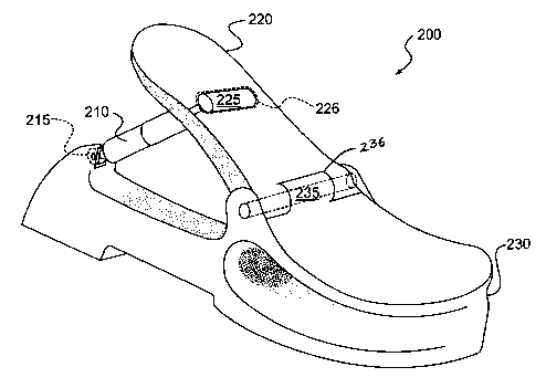
[0012] FIG. 2a shows various components of an exemplary embodiment of the
dynamic foot support platform of the present invention.
[0013] FIG. 2b shows a top view of a heel support shelf of the exemplary
dynamic
foot support platform of FIG. 2a.
[0014] FIG. 2c shows a perspective view of a heel support shelf of the
exemplary
dynamic foot support platform of FIG. 2a.
[0015] FIG. 2d shows a perspective view of a front portion of a foot support
shelf of
the exemplary dynamic foot support platform of FIG. 2a.
[0016] FIG. 3 shows a dynamic foot support platform according to another
exemplary
embodiment of the present invention.
[0017] FIG. 4 shows a side view of a dynamic foot support platform according
to
another exemplary embodiment of the present invention.
[0018] FIG. S shows a side view of a dynamic foot support platform according
to yet
another exemplary embodiment of the present invention.
[0019] FIG. 6a shows a side view of a dynamic foot support platform according
to
another exemplary embodiment of the present invention.
[0020] FIG. 6b shows an exemplary connector that is used for the dynamic foot
support platform in FIG. 6a.
[0021] FIG. 6c shows an exemplary connector used to connect various components
of
the dynamic foot support platform in FIG. 6a.
-3-
CA 02468535 2004-05-26
WO 03/049566 PCT/US02/39047
[0022] FIG. 6d shows a side view of a pivot area of the dynamic foot support
platform of FIG. 6a.
[0023] FIG. 6e shows an exemplary connector that is used for the dynamic foot
support platform in FIG. 6a.
[0024] FIG. 6f shows an exemplary connector that is used for the dynamic foot
support platform in FIG. 6a.
[0025] FIG. 7 shows a partial side view of a foot support platform according
to
another exemplary embodiment of the present invention.
[0026] FIG. 8a shows a side view of a dynamic foot support platform according
to an
exemplary embodiment of the present invention.
[0027] FIG. 8b shows an exemplary connector for attaching the components of
the
foot support platform in FIG. 8a.
[0028] FIG. 8c shows an exemplary connector that is used to connect various
components of the dynamic foot support platform of FIG. 8a.
[0029] FIG. 8d shows a side view of a pivot area of the dynamic foot support
platform of FIG. 8a.
[0030] FIG. 8e shows an exemplary connector for attaching the components of
the
foot support platform in FIG. 8a.
[0031] FIG. 8f shows an exemplary connector for attaching the components of
the
foot support platform in FIG. 8a.
[0032] FIG. 9a shows a back view of a dynamic foot support platform according
to an
exemplary embodiment of the present invention.
[0033] FIG. 9b shows the connectors of the foot support platform of FIG. 9a.
[0034] FIG. 9c shows a side view of the connectors of the foot support
platform of
FIG. 9a.
[0035] FIG. 10 shows a back view of a dynamic foot support platform according
to an
exemplary embodiment of the present invention.
[0036] FIG. 11 shows a back view of a dynamic foot support platform according
to an
exemplary embodiment of the present invention.
[0037] FIG. 12 shows a side view of a dynamic foot support platform according
to an
exemplary embodiment of the present invention.
[0038] FIG. 13a shows a side view of a pivot hinge according to an exemplary
embodiment of the present invention.
-4-
CA 02468535 2004-05-26
WO 03/049566 PCT/US02/39047
[0039] FIG. 13b shows a view along a length of the pivot hinge of FIG. 13a.
[0040] FIG. 14a shows an exemplary embodiment of a dynamic foot support
platform
according to an exemplary embodiment of the present invention.
[0041] FIG. 14b shows an exemplary embodiment of a dynamic foot support
platform
according to another exemplary embodiment of the present invention.
[0042] FIG. 15a shows an exemplary embodiment of footwear with a dynamic foot
support platform according to the present invention.
[0043] FIG. 15b shows an exemplary embodiment of footwear with a dynamic foot
support platform according to the present invention with a heel support shelf
in
various exemplary positions.
[0044] FIG. 16a shows an exemplary embodiment of a ski or snowboard boot with
a
dynamic foot support platform according to the present invention.
[0045] FIG. 16b shows an exemplary embodiment of an ice skate with a dynamic
foot
support platform according to the present invention.
[0046] FIG. 17 shows an exemplary embodiment of an inline skate or roller
skate
with a dynamic foot support platform according to the present invention.
DETAILED DESCRIPTION OF PREFERRED EMBODIMENTS
[0047] An exemplary device for dynamic foot support includes one or more
dampening devices that are used to decrease the magnitude of stresses that are
imposed on a foot during motion. Such a dampening device may be positioned at
or
near a heel area of footwear to provide dynamic motion to the bottom side of
feet.
Footwear with high heels may use such dampening devices to maintain a relative
height advantage while at the same time providing dynamic motion to the feet
to
prevent stresses imposed on the feet from high heels. Additionally, such
footwear
also provides a "spring" to the step of a user as the dampening device
provides a
reactive force that slightly propels the bottom of a foot. Consequently,
runners or fast
walkers can also benefit from the comfort of the present invention. Such
dynamic
foot support may be incorporated within any type of footwear to provide the
wearer a
dynamic response mechanism that decreases stresses imposed on the feet,
decreases
possible injuries, increases comfort and promotes health and safety.
Optionally, the
devices according to the present invention may be retroactively fit into
footwear.
[0048] FIG. 1 shows an exemplary embodiment of a dynamic foot support platform
100 according to the present invention. Although dynamic foot support platform
100
-5-
CA 02468535 2004-05-26
WO 03/049566 PCT/US02/39047
is presented in a given shape with particular features, the present invention
is not
limited to such an exemplary embodiment. Other dynamic foot support platform
embodiments are possible and are within the scope of the present invention.
Furthermore, footwear that includes such dynamic foot support platforms is
also
within the scope of the present invention.
[0049] An exemplary embodiment of a dynamic foot support platform according to
an embodiment of the present invention is illustrated in FIG. 2. A dynamic
foot
support platform 200 includes a heel support shelf 220 (FIGS. 2b and 2c) for
cradling
a heel end of the foot, a foot support shelf 230 (FIG. 2d) for cradling a
bottom side of
a foot, more particularly, the distal toes-end of the foot, and a dampening
device 210
for absorbing downward pressure on heel support shelf 220. Heel support shelf
220
typically is conformed to support a heel of a foot. Foot support shelf 230
typically is
conformed to support or cradle parts of the foot distal to the heel. Dampening
device
210 adjusts in length to conform to different pressures exerted by a foot on
platform
200.
[0050] Furthermore, dampening device 210 may be easily replaced in a given
foot
support platform so as to give the wearer more choices in dynamic reactivity
of the
footwear. Connectors that secure dampening device 210 within a foot support
platform 200 may be easily engaged or disengaged to allow the user a quick
replacement of the dampening device 210. Different dampening devices 210 may
provide different elasticity and reactive forces, thereby providing a range of
comfort
to a given wearer. The dynamic function of dampening device 210 within dynamic
foot support platform 200 is explained in more detail below.
[0051] Dampening device 210 enables heel support shelf 220 to adjust in
position
with respect to foot support shelf 230 by, for example, promoting rotation
about a
given rotating pivot area. Such a rotating pivot may be, for example, a pin
235 within
a pin-accommodating groove 236. Other configurations for the pivot area are
possible.
[0052] Dampening device 210 links heel support shelf 220 with foot support
shelf
230 via one or more connectors. An exemplary connector used to connect
dampening
device 210 to heel support shelf 220 is tubular snap-fit structure 225, which
is on an
end of dampening device 210. Tubular structure 225 is accommodated into
tubular
structure accommodating area 226 on heel support shelf 220. On the other end
of
-6-
CA 02468535 2004-05-26
WO 03/049566 PCT/US02/39047
dampening device 210 is another system of connectors 215 that securely connect
dampening device 210 to a heel end of foot support shelf 230. Other connector
systems can be used. Such other connector systems are described below.
[0053] When a pressure is exerted on platform 200 as a result of, for example,
a
downward motion of a foot during walking, dampening device 210 may adjust in
length. Such changes in length of dampening device 210 result in changes of
the
relative position of heel support shelf 220 with respect to foot support shelf
230
before and after the application of such a pressure. Conversely, when the same
pressure is reduced or withdrawn from the platform 200, then dampening device
210
increases in length, thereby again changing the relative position of heel
support shelf
220 with respect to foot support shelf 230. Such changes in the length of
dampening
device 210 results in a cushioning of the step for the wearer, which is more
comfortable, safer, and less painful for the wearer. The same principles apply
to all of
the exemplary embodiments shown here.
[0054] FIG. 3 illustrates a dynamic foot support platform according to another
exemplary embodiment of the present invention. A dynamic foot support platform
300 includes a dampening device 310, a heel support shelf 320, and a foot
support
shelf 330. Dampening device 310 is connected to a heel 336 of foot support
shelf 330
via a connector, which may be, for example, a pivot and bracket configuration
312.
An interior bracket support 337 may be used to anchor the bracket of the
bracket
configuration 312 securely within foot support shelf 330. Interior bracket
support 337
may be, for example, hard plastic, metal, or suitable material that can act as
an anchor
within foot support shelf 330. A connector, such as a hinge 340, links heel
support
shelf 320 with foot support shelf 330.
[0055] Foot support shelf 330 may be in the shape of an elongated,
substantially
planar surface that supports a user's foot, extending from a toe area to a
heel area.
Alternatively, foot support shelf 330 may be non-uniform across its length and
have
grooves or ridges 332 along its body for functional or stylish purposes. Other
shapes,
for example cut outs or geometrical designs, can be used. A layer of
protective
material 350 may be positioned atop of hinge 340 to promote the durability of
hinge
340. Additionally, the layer of protective material 350 protects the bottom of
a foot
from getting injured by contact with the moving mechanism of hinge 340. Layer
of
protective material 350 may be, for example, a pad, a tape, a sponge, or other
suitable
CA 02468535 2004-05-26
WO 03/049566 PCT/US02/39047
protective material. Furthermore, an interior layer of support material 345
for hinge
340 promotes the flexibility of the hinge mechanism while maintaining
structural
integrity. For example, the interior layer of support material 345 may be
substantially
stiff but with enough flexibility to allow the motion of heel support shelf
320 when an
application is applied thereon.
[0056] FIG. 4 illustrates a dynamic a foot support platform 400 according to
another
exemplary embodiment of the present invention. Dynamic foot support platform
400
includes a dampening device 410, a heel support shelf 420 and foot support
shelf 430.
Additionally, a layer of lining 450 is positioned on top of the heel support
shelf 420
and foot support shelf 430 such that the layer of lining 450 spans across the
entire
length of the underside of a foot, from a heel area to a toe area. Such a
layer of lining
450 may be composed of, for example, a cushioned rubber, leather, foam,
fabric, ,
rubber, or similar material. Other suitable materials are possible and within
the scope
of this invention. A portion of the layer of lining 450 is recessed into the
foot
platform 400 to secure the lining within the heel support shelf 420 and foot
support
shelf 430.
[0057] FIG. 5 illustrates another exemplary embodiment of the present
invention. A
dynamic foot support platform 500 includes a dampening device 510, a heel
support
shelf 520 and a foot support shelf 530. Dampening device 510 is linked to heel
support shelf 520 and foot support shelf 530 through connectors 522 and 512,
respectively. An internal heel support 562 anchors part of connector 512 to
foot
support shelf 530. Internal heel support 562 may be, for example, hard
plastic, metal,
or suitable material that can act as an anchor within foot support shelf 530.
[0058] A heel pad 580 and a sole pad 581 are used to further cushion each step
as a
user walks with footwear that incorporates foot support platform 500. Heel pad
580
and sole pad 581 may be composed of, for example, rubber, plastic, metal, or
other
suitable material or combinations thereof used for heel/sole pads.
[0059] All parts of dynamic foot support platform 500 other than heel pad 580
and
sole pad 581 may be composed of durable, lightweight materials, such as, for
example, carbon fiber, urethane, plastics, lightweight alloy metals, including
aluminum, steel, and titanium, other suitable material, or combinations
thereof. These
materials may be used for any of the other embodiments shown and described
herein.
Other suitable materials are possible, such as hollow hardened steel.
Additionally,
_g_
CA 02468535 2004-05-26
WO 03/049566 PCT/US02/39047
each component of shoe platform 500, other than dampening device 510, may be
wrapped by carbon fiber for increased strength and durability. A technique of
integrating carbon fiber and metal in the manufacturing process may be the
well
known Bladder Mold Method. In such a method, a carbon fiber may be wrapped
around all of the non-critical areas of the metal, the critical areas being
the attachment
points.
[0060] Connectors 512 and 522 are shown in FIG. 5 as threaded retainer pins as
an
example. Other types of connectors including snap fit connectors, hook
connectors,
hinges, screw-type rods, or suitable connectors may be used. Rotating pivot
535 is
shown as a rod rotating in a rod-accommodating slot. Other types of rotating
mechanisms can be used, including an indented, perforated, or crumbled region
of
hard plastic that allows motion of heel support shelf 520 with respect to foot
support
shelf 530 about rotating pivot 535 without sacrificing structural stability.
Optionally,
the material properties of a given sheet of material may be altered at a
particular
region or line to enable increased flexibility in such an altered region or
line resulting
in creation of, for example, a pivoting region.
[0061] A protective cover 570 is positioned across a region extending between
heel
support shelf 520 and foot support shelf 530. Protective cover 570 prevents
rotating
pivot 535 from injuring the bottom of a user's foot that is positioned atop
the foot
platform 500. A front end of protective cover 570 may be secured in a
protective
cover slot 571 in foot support shelf 530 that allows freedom of movement of
protective cover 570 independent of any motion of heel support shelf 520 with
respect
to foot support shelf 530. Alternatively, protective cover 570 may be glued or
otherwise attached to the surfaces of heel support shelf 520 and foot support
shelf
530. It would be apparent to those skilled in the art that other methods of
attachment
can be used.
[0062] FIG. 6 illustrates an embodiment of a dynamic foot support platform
according to another embodiment of the present invention. As dynamic foot
support
platform 600 is used, such as during walking, downward forces of the wearer's
body
through the feet are exerted onto heel support shelf 620, resulting in
relative
downward and upward motions of heel support shelf 620. All such downward and
upward motions of heel support shelf 620 are possible by rotation of an end of
heel
_g_
CA 02468535 2004-05-26
WO 03/049566 PCT/US02/39047
support shelf 620 in an arc about rotating pivot 640. This mechanism is also
present
in the other embodiments shown and described herein.
[0063] In use, a downward force on foot platform 600 results in a downward
motion
of heel support shelf 620 in the direction of arrow 601 and a rotation about
pivot 640
in the arc direction of arrow 603. Any decrease in downward force on foot
platform
600 results in an upward motion of heel support shelf 620 in the direction of
arrow
602 and a rotation about pivot 640 in the arc direction of arrow 604.
[0064] A connector 625 is a standard metal pin as an example. It would be
apparent
to those skilled in the art that other types of connectors can be used.
Connectors 626,
627, 628, and 629 shown in FIGS. 6b, 6c, 6e, and 6f, respectively, are other
examples
of connectors. Connectors 626 and 627 are press fit connectors that are
pressed into a
slot (not shown) on the bottom side of heel support shelf 620 to create a
tight fit.
Different geometries may be used for press fit connectors, such as, for
example, a
cylindrical head 626 or a spherical head 627. Another connector 628 that may
be
used is a head with a slot for a pin (not shown), which would be positioned on
the
bottom side of heel support shelf 620.
[0065] Another connector 629 is in the shape of an incomplete cylinder and is
an
integral component of dampening device 610. This connector 629 may be snapped
or
pressed into a slot (not shown) in heel support shelf 620 and is connected to
body 632
of dampening device 610 through a neck region 631. The widened head of
connector
629 provides increased surface area for distribution of downward forces on
dampening device 610, thereby decreasing the stress at any given point on the
top
surface of connector 629. This is one method that strengthens the connection
between
heel support shelf 620 and dampening device 610. Other strengthening methods
are
also possible.
[0066] FIG. 7 illustrates a cutaway partial side view of a dynamic foot
support
platform according to another exemplary embodiment of the present invention. A
dynamic foot support platform 700 has a heel support shelf 720 that includes
an
internal layer of material 721 that increases strength and durability while
decreasing
weight. Layer of material 721 may be, for example, a carbon fiber. Other types
of
material are possible. An inlaid heel 738 and sole 739 may be composed of
materials
that further promote dampening of each step. Such materials for heel 738 and
sole
-10-
CA 02468535 2004-05-26
WO 03/049566 PCT/US02/39047
739 include, for example, rubber, plastic, metal, another suitable material,
or
combinations thereof.
[0067] Heel support shelf 720 also contains an interior support bracket 730.
Interior
support bracket 730 has an upper arm 722 that extends from a connector at a
top
portion of dampening device 710 to rotating pivot 740. A lower arm 745
fizrther
extends from rotating pivot 740 into foot support shelf. The combination of
upper
arm 722 and lower arm 745 strengthens the area around rotating pivot 740,
thereby
promoting the longevity of the rotating mechanism.
[0068] On the other end of dampening device 710 is an internal support bracket
737
that extends from a connector at a bottom portion of dampening device 710.
This
multiple system of support brackets positioned on each end of and in
connection to
dampening device 710 promotes an increase in structural stability of dynamic
foot
support platform 700 by giving an internal skeletal structure to the areas of
the foot
platform 700 where there will be stress created from a walking motion of the
user.
The increase in structural stability promotes durability of dynamic foot
support
platform 700, thereby increasing the life of footwear that incorporates it.
[0069] FIG. 8 illustrates a dynamic foot support platform 800 according to
another
embodiment of the present invention. As dynamic foot support platform 800 is
put
into use, such as during walking, downward forces of the body through the feet
are
exerted onto heel support shelf 820, resulting in downward and upward motions
of
heel support shelf 820. All such upward and downward motions of heel support
shelf
820 are possible by rotation of an end of heel support shelf 820 in an arc
about
rotating pivot 840.
[0070] In use, a downward force on foot platform 800 results in a downward
motion
of heel support shelf 820 in the direction of arrow 801 and a rotation about
pivot 840
in the arc direction of arrow 803. Any relative decrease in downward force on
foot
platform 800 results in an upward motion of heel support shelf 820 in the
direction of
arrow 802 and a rotation about pivot 840 in the arc direction of arrow 804.
[0071] Connector 825 is shown in FIG. 8a as a press fit connector as an
example.
Other types of connectors are possible. Connectors 826, 827, 828, and 829,
shown in
FIGS. 8b, 8c, 8e, and 8f, respectively, are other examples of connectors that
may be
substituted for connector 825 in FIG. 8a. Connectors 826 and 827 are press fit
connectors that are pressed into a slot on the bottom side of heel support
shelf 820 to
-11-
CA 02468535 2004-05-26
WO 03/049566 PCT/US02/39047
create a tight fit. Different geometries may be used for press fit connectors,
such as,
for example, a cylindrical head 826 or a spherical head 827.
[0072] Another connector 828 that may be used is a head with a slot for a pin
(not
shown), which would be positioned on the bottom side of heel support shelf
820.
Another connector 829 is in the shape of an incomplete cylinder and is an
integral
component of dampening device 810. This connector 829 may be snapped or
pressed
into a slot in heel support shelf 820 and is connected to body 833 of
dampening
device 810 through a neck region 831. The widened head of connector 829
provides
more surface area for distribution of downward forces on dampening device 810,
thereby decreasing the stress at any given point on the top surface of
connector 829.
[0073] FIG. 9 illustrates a rear view of a dynamic foot support platform 900
according to another exemplary embodiment of the present invention. Dynamic
foot
support platform 900 includes a dampening device 910 in connection with a heel
support shelf 920. In the embodiment illustrated, connector 922 is a tight-fit
connector. It would be apparent to those skilled in the art that other
connectors can be
used. The other end of dampening device 910 includes a mount protrusion 913
that is
accommodated into a mount protrusion slot 914 located in a heel portion 936 of
foot
support shelf 930. A retainer rod or pin may be positioned in retainer housing
915,
which is perpendicular to mount protrusion 913. Any such rod or pin locks into
and
secures mount protrusion 913 with heel portion 936. The relationship between
mount
protrusion 913, mount protrusion accommodating slot 914, and retainer housing
915
is also shown in FIG. 9b from the opposite view of FIG. 9a, and in FIG. 9C
from a
side view of FIG. 9a. Other connections, protrusion, and mounting mechanisms
are
possible.
[0074] FIG. 10 shows another exemplary embodiment of a dynamic foot support
platform according to the present invention. A dynamic foot support platform
1000
includes a dampening device 1010, a heel support shelf 1020, and a foot
support shelf
1030. Dampening device 1010 is secured to heel support shelf 1020 through
connector 1023 in accommodating slot 1022, which configuration is shown in
FIG. 10
as a press fit connection. It would be apparent to those skilled in the art
that other
types of connectors can be used. A rotating pivot 1040 enables relative
movement of
heel support shelf 1020 with respect to foot support shelf 1030 when a force
applied
-12-
CA 02468535 2004-05-26
WO 03/049566 PCT/US02/39047
to a top side of foot platform 1000 causes a decrease in length of dampening
device
1010, such as during compression.
[0075] Dampening device 1010 is secured to a heel area 1036 of foot support
shelf
1030 via a connector, which is shown by example in FIG. 10 as a pin 1012 and
bracket 1013. It would be apparent to those skilled in the art that other
types of
connectors can be used. To further increase the strength of the connection
between
dampening device 1010 and heel area 1036, an internal support structure 1037
is
housed inside heel area 1036 that anchors bracket 1013 to heel area 1036. Such
a
configuration promotes structural stability and the capability of withstanding
higher
stresses applied to foot platform 1000 without breaking, such as encountered,
for
example, during rapid walking or running.
[0076] FIG. 11 illustrates a dynamic foot support platform according to
another
embodiment of the present invention. A dynamic foot support platform includes
substantially the same general components as dynamic foot support platform
1000,
except the optional differences as described in detail herein. A connector
1122, which
secures dampening device to heel support shelf has a retaining pin that
retains a top
protrusion of dampening device. It would be apparent to those skilled in the
art that
other types of connectors can be used.
[0077] A layer of support material 1160 spans the length of heel support shelf
1120
and foot support shelf 1130. Layer 1160 of material may be composed of carbon
fiber, hardened plastic, or other suitable material that adds structural
stability to
dynamic foot support platform 1100 and maintains strength during dynamic
motion.
Such a layer of support material 1160 may also span across a bottom side of
heel
support shelf 1120 to protect rotating pivot 1140. Alternatively, such layer
of support
material 1160 may be positioned within the body of heel support shelf 1120,
atop heel
support shelf 1120, or combinations thereof. A pin 1112 secures a bottom end
of
dampening device 1110 to a retaining bracket 1162. Retaining bracket 1162 is a
unitary structure with an upper end having slots for retaining pin 1112, and a
bottom
anchor that is securely fastened within a heel area of foot support shelf.
Having a
unitary structure retaining bracket 1162 as shown in FIG. 11 as opposed to
multiple
retaining bracket structure as shown in FIG. 10 decreases the number of parts,
the
cost, and the complexity of manufacturing.
-13-
CA 02468535 2004-05-26
WO 03/049566 PCT/US02/39047
[0078] The above exemplary embodiments of various foot support platforms
according to the present invention are shown with a dampening device
positioned at a
particular angle with respect to a heel support shelf. Furthermore, a single
dampening
device has been shown in each exemplary embodiment for sake of simplicity.
However, other angles and positions of dampening device are also possible, as
well as
multiple dampening devices. Dampening devices may be positioned in any
direction
that could benefit from a dampening of forces.
[0079] FIG. 12 is a diagram illustrating another embodiment of the dynamic
foot
support platform 1200 according to an embodiment of the present invention.
FIG. 12
shows another angle and position of dampening device 1210 in foot support
platform
1200. Dampening device 1210 is secured to heel support shelf 1220 using
connectors
as shown and described in the above exemplary embodiments. However, the bottom
end of dampening device 1210 is secured to foot support shelf 1230 using a
bracket
1250 that protrudes from a position that is more internal than the exemplary
embodiments shown and described above. Such position of bracket 1250 enables
dampening device 1210 to have a different angle with respect to other examples
shown and described above.
[0080] Furthermore, as with other examples described above, an internal
support
structure 1222 is shown in light shade that extends a length of the body of
heel
support shelf 1220, from a top portion of dampening device 1210, past rotating
pivot,
and into foot support shelf 1230. For example, internal support structure 1222
may be
a metal support wrapped with a carbon fiber to provide additional structural
support to
the portions of dynamic foot support platform 1200 that may be in more direct
contact
with the forces exerted from the bottom side of a foot.
[0081] Other exemplary embodiments of foot platforms according to the present
invention are shown in FIGS. 14a and 14b. In FIG. 14a, foot platform 1400
includes
a dampening device 1460 positioned very close to a center position of foot
platform
1400. Dampening device 1460 is secured between base structure 1401 and heel
support shelf 1402. A rod 1410 extends upwards from base structure 1401 at a
back
end of foot platform 1400. Rod 1410 is slideably engaged with rod
accommodating
structure 1420 that receives a portion 1430 of rod 1410. When a user is in
motion, as
when walking, downward forces on heel support shelf 1402 cause a downward
movement of heel support shelf 1402 about a pivot point 1403 such that rod
1410 is
-14-
CA 02468535 2004-05-26
WO 03/049566 PCT/US02/39047
further inserted into rod accommodating structure 1420, thereby resulting in
an
increased portion 1430 of rod 1410 positioned within rod accommodating
structure
1420.
[0082] Foot platform 1450 as shown in FIG. 14b is substantially similar to
foot
platform 1400 shown in FIG. 14a, but with the following noted alternative
positioning
of components. The most external component of pivot point 1403 on foot
platform
1400 is heel support shelf 1402. Alternatively, the most external component of
pivot
point 1403 on foot platform 1450 is base structure 1401. Furthermore, a
rotation
guide structure 1404 guides proper rotation of base structure 1401 in the
exemplary
embodiment shown in FIG. 14b. Other embodiments are also possible. An
advantage
of positioning dampening device 1460 very close to pivoting point 1403 is that
dampening device 1460 may be hidden from view and therefore not have to be
exposed prominently on a given foot platform. Hiding a dampening device may be
beneficial from an aesthetic or safety perspective.
[0083] The exemplary embodiments shown in FIGS. 14a and 14b may have
alternative relative moving components. In one example, base structure 1401
may be
relatively static and heel support shelf 1402 moves in an arc relative to base
structure
1401. Alternatively, heel support shelf 1402 may be relatively static and base
structure 1401 moves in an arc relative to heel support shelf 1402. Other
movement
mechanisms are also possible.
[0084] The above exemplary embodiments are described having a standard
rotating
pivot in the form of a rotating pin. However, many different alternatives are
also
possible as long as they allow for movement of a heel support shelf with
respect to a
foot platform.
[0085] Another exemplary embodiment of a rotating pivot that may be used with
the
dynamic foot support platform of the present invention is shown in FIG. 13.
Such a
pivot may be, for example, a hinge 1300 that includes a mechanism that permits
locking of hinge 1300 in various positions. Hinge 1300 has a generally
elongated
hinge body 1330 that ends in a push button head 1310, which may be rubber or
other
suitable material. Interior of push button head 1310 is push button actuator
1320 that
is connected to a push button shaft 1370. A spring 1360 surrounds push button
sliding shaft 1370 and is limited to a space between push button actuator 1320
and a
stationary wall 1340, which can be a notch-toothed nut with a hollow core.
-15-
CA 02468535 2004-05-26
WO 03/049566 PCT/US02/39047
[0086] A second wall 1350 accommodates the end of push button sliding shaft
1370
and is designed to mate with stationary wall 1340. Second wall 1350 may be a
notched tooth nut. FIG. 13b shows a side cut view of the notched areas of
walls 1340
and 1350 showing the alternating position of a tooth 1390 and gap
accommodating
space 1389 that engages a tooth on the mating wall. In use, hinge 1300 enables
securing a relative position of a heel support shelf with respect to a foot
support shelf,
as will be described with respect to FIG. 15.
[0087] In the exemplary embodiment shown in FIG. 15, a shoe 1500 is shown
having
a heel support shelf 1520, a foot support shelf 1530, and a heel 1510.
Rotating pivot
1540 enables heel support shelf 1520 to pivot with respect to the rest of the
shoe
1500. A top band 1550 and a bottom band 1560 are used to secure the shoe to a
wearer's foot. Heel support shelf 1520 may be in one or more exemplary
positions
1501, 1502, 1503, as when a user is walking. A dampening device is not shown
in
FIG. 15 for sake of clarity. However, such a dampening device may be placed
within
foot support shelf 1530 and hidden from outside view, similarly to the
structure
shown in FIG. 14.
[0088] Alternatively, shoe 1500 shown in FIG. 15 may not need a dampening
device
in order to still have range of motion in heel support shelf 1520 as long as
rotating
pivot 1540 is a hinge such as hinge 1300, shown and described with respect to
FIG.
13. If hinge 1300 is used as rotating pivot 1540 in shoe 1500, then the user
will have
options of the relative position of heel support shelf 1520, such as options
1501, 1502,
and 1503. Furthermore, in the exemplary embodiment shown in FIG. 15, a user
has
the option of adjusting a shoe to be high-heeled, moderate pump, or relatively
flat,
depending on the desired height of heel support shelf 1520.
[0089] However, without a dampening device, shoe 1500 will not have a dynamic
reacting mechanism that senses downward stresses and reacts to it through a
dampening device to provide reactive upward stresses. It is possible for given
footwear to include both a dampening device and a hinge 1300 as shown in FIG.
13.
If both such options are used, then a user will still maintain reactive
footwear, but one
that is adjustable to different levels of full motion. Other options are
possible.
[0090] Although the above exemplary embodiments of the present invention are
generally shown and described using standard footwear, such as shoes and
boots, the
present invention is not limited to such use and may be used in other
footwear. FIG.
-16-
CA 02468535 2004-05-26
WO 03/049566 PCT/US02/39047
16a shows an exemplary embodiment of a ski or snow board boot 1600
incorporating
a dynamic foot support platform of the present invention as shown and
described
above. Boot 1600 includes a foot-securing component 1620 that is connected to
a
dampening device 1610. A locking base 1630 is also connected to the foot-
securing
component 1620 and the opposite end of dampening device 1610.
[0091] In use, as a wearer glides down a mountain slope, various moguls and
bumps
cause relative upward and downward stresses on the foot strapping component
1620
of boot 1600. These transferred forces are then sensed by dampening device
1610,
which then cushions some of the forces and causes reactive stresses that push
back
upward through the dampening device 1610 and the foot strapping component
1620.
In real time motion, foot-securing component 1620 is in a constant upward and
downward motion about pivot point 1640, thereby cushioning the stresses
normally
felt on the bottom side of a wearer's foot. Optionally, a cover 161 S may
conceal or
protect dampening device 1610 from view and protect it from snow and debris
that
may decrease its functional life.
[0092] Another exemplary embodiment of footwear having a dynamic foot support
platform according to an embodiment of the present invention incorporated
within it
is an ice skate 1601 shown in FIG. 16b. Ice skate 1601 functions in a similar
way as
described with respect to ski or snow boot 1600 in FIG. 16a. Foot-securing
component 1621 moves about pivoting point 1641 with respect to blade 1631 by
relative length changes of dampening device 1611. For sake of simplicity, ice
skate
1600 is shown having a dampening device 1611 that is visible because it has no
protective cover 1615. Such a cover 1615 may be secured between foot-securing
component 1621 and blade 1631 to protect dampening device 1611 from debris.
[0093] In another exemplary embodiment of footwear incorporating a dynamic
foot
platform according to an embodiment of the present invention, an inline skate
or roller
skate 1700 is shown in FIG. 17. Inline skate 1700 has a foot-securing
component
1720 that is connected to both a dampening device 1710 and a wheelbase 1730.
Dampening device 1710 is also connected to wheelbase 1730. Any relative motion
of
foot accommodating component 1720 with respect to wheelbase 1730 is possible
by
rotation about pivot point 1740 caused by changes in the length of dampening
device
1710.
-17-
CA 02468535 2004-05-26
WO 03/049566 PCT/US02/39047
[0094] There are many advantages in footwear that incorporate the present
invention
over conventional static footwear. A user wearing footwear having a dynamic
foot
platform will not expose his or her feet to repeated static forces caused by a
hard
ground. Another advantage of the present invention is that it allows for
motion of the
foot itself within the footwear, such that the foot is bent and flexed during
natural
walking motion, promoting comfort and blood flow. Furthermore, users wearing
high
heel shoes incorporating foot support platforms according to the present
invention
will be able to wear such high heel shoes for more extended periods of time
without
feeling the discomfort typical of high heel shoes. The frequency of broken
heels also
decreases because the stresses that are created during typical walking or
running with
shoes having high heels is dampened using a dampening device, therefore
resulting in
less inconvenience and cost to the wearer from an inopportune broken heel.
Finally,
an adjustable tension in a dampening device and/or pivoting hinge allows a
user to
specify the range of motion that is most comfortable in a footwear that
incorporates
such a dynamic foot support platform. Many other advantages are evident that
relate
to comfort, safety, and fashion.
[0095] Although the above embodiments are described in a specific manner with
specific components, the present invention is not limited to such
configurations. For
example, the above exemplary embodiments are described using a dampening
device
that appears as a shock absorber, much like those used in a vehicle or
bicycles.
However, other types of dampening devices are possible. If a shock absorber is
used,
it may be pre-determined to move a limited distance, such as, for example, in
a range
of 0.75 to 1.00 inches. The shock absorber may be manufactured using a metal
that is
best suited for its particular use. An exemplary shock absorber that may be
used with
the present invention may be a conventional shock absorber, but which may have
to
be altered to fit the present function. Various shock absorbers may be rated
for
groups of different weight users, such as, for example, "for 110 to 120
pounds". In
addition, adjustable shock absorbers can be used to accommodate different
wearers or
to allow a wearer to "tune" to a comfortable setting. Furthermore, more than
one
shock absorber may be used in given footwear, such as up to four shock
absorbers.
Various positions may be selected for each shock absorber, for example, up and
down, backward or forward in relation to the footwear, or other suitable
positions.
-18-
CA 02468535 2004-05-26
WO 03/049566 PCT/US02/39047
Finally, the shock absorber may be air, oil, or spring reinforced. Other types
are also
possible.
[0096] Any footwear as described above, and all of its suitable components,
may be
manufactured with carbon fiber using conventional manufacturing techniques,
such
as, injection or vacuum molding. Such processes allow hollow solid shapes to
be
formed without seams and thickness discrepancies. Furthermore, such processes
provide a lightweight and rigid form. Other materials, such as urethane or
plastic,
may also be used to manufacture such footwear. Urethane or plastic may reduce
the
amount of tooling and overall production expenses. Use of certain specialized
materials, such as urethane, further reduces manufacturing costs while still
maintaining structural integrity because the overall number of components and
manufacturing steps may be reduced. For example, a uniform body of urethane
may
be used to manufacture substantially the entire shoe support according to the
present
invention, including connectors and brackets, and further eliminating the need
for
structural inserts. Finally, the body portion of footwear that accommodates a
dynamic
mechanism as described herein may have to endure stretching as a result of
such
motion without buckling up. Exemplary types of materials that may be used for
such
body portion may be, for example, leather, rubber, hybrid materials, or other
suitable
materials.
(0097] In describing representative embodiments of the invention, the
specification
may have presented the method and/or process of the invention as a particular
sequence of steps. However, to the extent that the method or process does not
rely on
the particular order of steps set forth herein, the method or process should
not be
limited to the particular sequence of steps described. As one of ordinary
skill in the
art would appreciate, other sequences of steps may be possible. Therefore, the
particular order of the steps set forth in the specification should not be
construed as
limitations on the claims. In addition, the claims directed to the method
and/or
process of the invention should not be limited to the performance of their
steps in the
order written, and one skilled in the art can readily appreciate that the
sequences may
be varied and still remain within the spirit and scope of the invention.
[0098] The foregoing disclosure of the embodiments of the invention has been
presented for purposes of illustration and description. It is not intended to
be
exhaustive or to limit the invention to the precise forms disclosed. Many
variations
-19-
CA 02468535 2004-05-26
WO 03/049566 PCT/US02/39047
and modifications of the embodiments described herein will be apparent to one
of
ordinary skill in the art in light of the above disclosure. The scope of the
invention is
to be defined only by the claims appended hereto, and by their equivalents.
-20-