Language selection

Search

Patent 2468834 Summary

Third-party information liability

Some of the information on this Web page has been provided by external sources. The Government of Canada is not responsible for the accuracy, reliability or currency of the information supplied by external sources. Users wishing to rely upon this information should consult directly with the source of the information. Content provided by external sources is not subject to official languages, privacy and accessibility requirements.

Claims and Abstract availability

Any discrepancies in the text and image of the Claims and Abstract are due to differing posting times. Text of the Claims and Abstract are posted:

  • At the time the application is open to public inspection;
  • At the time of issue of the patent (grant).
(12) Patent: (11) CA 2468834
(54) English Title: DISPLAY APPARATUS
(54) French Title: APPAREIL D'AFFICHAGE
Status: Expired and beyond the Period of Reversal
Bibliographic Data
(51) International Patent Classification (IPC):
  • G09F 15/00 (2006.01)
  • G09F 21/04 (2006.01)
(72) Inventors :
  • COOK, SAM (United Kingdom)
(73) Owners :
  • URBAN STORM LIMITED
(71) Applicants :
  • URBAN STORM LIMITED (United Kingdom)
(74) Agent: MARKS & CLERK
(74) Associate agent:
(45) Issued: 2011-02-22
(86) PCT Filing Date: 2002-11-29
(87) Open to Public Inspection: 2003-06-12
Examination requested: 2007-11-14
Availability of licence: N/A
Dedicated to the Public: N/A
(25) Language of filing: English

Patent Cooperation Treaty (PCT): Yes
(86) PCT Filing Number: PCT/GB2002/005392
(87) International Publication Number: GB2002005392
(85) National Entry: 2004-05-31

(30) Application Priority Data:
Application No. Country/Territory Date
0128639.2 (United Kingdom) 2001-11-29

Abstracts

English Abstract


A pair of elongate holding devices (7a, 7c) extending along opposite sides of
an
imaginary rectangle have respective longitudinal recesses (12, 21) which hold
respective
edge portions (6a, 6c) of a poster (6). One holding device (7c) has a fixed
bearing
member (16) and a movable member (18) which contains the recess (21) and which
is
pivotable about a pivot axis (19) from an active position, in which the recess
(21) is open
in a direction away from the opposite holding device so that the poster (6)
turns back on
itself near the edge portion (6c), the poster being under tension between the
pair of
holding devices, to a passive position, in which tension in the poster is
released
sufficiently to allow the edge portion (6c) to be removed from the recess
(21).


French Abstract

L'invention concerne deux dispositifs de retenue allongés (7a, 7c) s'étendant sur les côtés opposés d'un rectangle imaginaire, qui présentent des évidements longitudinaux (12, 21) respectifs qui retiennent les bords (6a, 6c) respectifs d'une affiche (6). Un dispositif de retenue (7c) est pourvu d'un élément d'appui fixe (16) et d'un élément amovible (18) renfermant l'évidement (21) qui tourne autour d'un axe (19) à partir d'une position active, dans laquelle ledit évidement (21) est ouvert éloigné du dispositif de retenue opposé, de sorte que l'affiche (6) fait demi-tour sur elle-même à proximité du bord (6c), ladite affiche étant sous tension entre les deux dispositifs de retenue, vers une position passive, dans laquelle la tension de l'affiche se relâche suffisamment pour permettre au bord (6c) de quitter l'évidement (21). Le dispositif de retenue (7a) est, de préférence, un dispositif de retenue supérieur doté d'une fente de dégagement (12) qui reçoit coulissant un bourrelet (14) au niveau du bord supérieur (6a) de l'affiche. L'élément amovible (18) présente des taquets coopérant avec des surfaces d'appui cylindriques sur l'élément d'appui fixe (16) pour assurer qu'aucune tension locale excessive n'est appliquée au dispositif de retenue (7c).

Claims

Note: Claims are shown in the official language in which they were submitted.


6
The embodiments of the invention in. which an exclusive property or privilege
is
claimed are defined as follows:
1. Display apparatus comprising at least one pair of elongate holding devices
extending along opposite sides of an imaginary rectangle, the holding devices
having
respective longitudinal recesses which hold respective edge portions of a
poster, at least
one holding device of the pair comprising a fixed bearing member and a movable
member which contains the recess and which is pivotable about a pivot axis
relative to
the fixed bearing member from (a) an active position, in which the recess is
open in a
direction away from the opposite holding device so that the poster turns back
on itself
near the edge portion, the poster being under tension between the pair of
holding devices,
to (b) a passive position, in which tension in the poster is released
sufficiently to allow
the edge portion to be removed from the recess of the said one holding device;
in which
the fixed bearing member has a fixed end portion, an intermediate portion, and
a free end
portion, the intermediate portion has a convex bearing surface, part of which
is partially
cylindrical, the free end portion has a cylindrical external bearing surface
coaxial with the
partially cylindrical part of the convex bearing surface of the intermediate
portion but of
smaller diameter, the movable member has first and second longitudinal wings
which
define between them an open cavity to receive the free end portion and
intermediate
portion of the fixed bearing member, the first wing has in the cavity a
concave partially
cylindrical bearing surface which matches the cylindrical external bearing
surface of the
free end portion, the first wing is received in a space between the free end
portion and the
intermediate portion of the fixed bearing member when the movable member is in
its
passive position, and the second wing has in the cavity a concave surface
which fits
against the convex bearing surface of the intermediate portion when the
movable member
is in its active position.
2. Display apparatus comprising at least one pair of elongate holding devices
extending along opposite sides of an imaginary rectangle, the holding devices
having
respective longitudinal recesses for holding respective edge portions of a
poster, at least
one holding device of the pair comprising a fixed bearing member and a movable
member which contains the recess and which is pivotable about a pivot axis
relative to
the fixed bearing member from (a) a passive position, in which the edge
portion of a

7
poster is insertable into the recess while the poster is held by the opposite
holding device,
to (b) an active position, in which the recess is open in a direction away
from the opposite
holding device so that the poster turns back on itself near the edge portion,
motion from
the passive position to the active position applying tension to the poster;
wherein in
which the fixed bearing member has a fixed end portion, an intermediate
portion, and a
free end portion, the intermediate portion has a convex bearing surface, part
of which is
partially cylindrical, the free end portion has a cylindrical external bearing
surface
coaxial with the partially cylindrical part of the convex bearing surface of
the
intermediate portion but of smaller diameter, the movable member has first and
second
longitudinal wings which define between them an open cavity to receive the
free end
portion and intermediate portion of the fixed bearing member, the first wing
has in the
cavity a concave partially cylindrical bearing surface which matches the
cylindrical
external bearing surface of the free end portion, the first wing is received
in a space
between the free end portion and the intermediate portion of the fixed bearing
member
when the movable member is in its passive position, and the second wing has in
the
cavity a concave surface which fits against the convex bearing surface of the
intermediate
portion when the movable member is in its active position.
3. Display apparatus as claimed in claim 1 or 2, in which the movable member
is
connected to the fixed bearing member so that the movable member cannot be
removed
from the fixed member in any direction transverse to the pivot axis.
4. Display apparatus as claimed in claim 3, in which the wings cooperate with
the
free end portion and the intermediate portion of the fixed bearing member so
as to
prevent separation of the movable member from the fixed bearing member in any
direction transverse to the pivot axis.
5. Display apparatus as claimed in 1 or 2, in which the said one pair of
holding
devices are a fixed upper holding device and a lower holding device which
constitutes the
said one holding device, the recess of the upper holding device being in the
form of an
undercut slot in an underside of the upper holding device, for accommodating a
longitudinal bead on an upper edge portion of the poster so that the bead can
be slid

8
along the recess when a lower edge portion of the poster is free of the lower
holding
device.
6. Display apparatus as claimed in claims 1 or 2, in which the said one pair
of
holding devices are lateral holding devices.
7. Display apparatus as claimed in claim 6, in which one lateral holding
device
constitutes the said one holding device, the other lateral holding device
being a fixed
holding device having a longitudinal recess which is open in a direction away
from the
said one holding device.
8. Display apparatus as claimed in claim 6, including an upper holding device
having an undercut slot in an underside thereof, for accommodating a
longitudinal bead
on an upper edge portion of the poster so that the bead can be slid along the
upper
holding device when a lower edge portion of the poster is free.
9. Display apparatus as claimed in claim 8, including a lower holding device
comprising a fixed bearing member and a movable member pivotable relative to
the fixed
member.

Description

Note: Descriptions are shown in the official language in which they were submitted.


CA 02468834 2009-12-16
DISPLAY APPARATUS
FIELD OF THE INVENTION
This invention relates to apparatus for displaying a poster. In this
specification
the word "poster" is used as a general term and includes any form of sheet
material
bearing an image, artwork, or lettering, e.g. an advertising banner.
BACKGROUND
It is known to mount a poster in display apparatus comprising a frame fixed to
a
support such as a wall, a light box, or the side of a vehicle.
SUMMARY OF THE INVENTION
What is desired is display apparatus which facilitates mounting and removal of
a poster.
In one aspect the invention provides display apparatus comprising at least one
pair of elongate holding devices extending along opposite sides of an
imaginary
rectangle, the holding devices having respective longitudinal recesses which
hold
respective edge portions of a poster, at least one holding device of the pair
comprising a
fixed bearing member and a movable member which contains the recess and which
is
pivotable about a pivot axis relative to the fixed bearing member from an
active
position, in which the recess is open in a direction away from the opposite
holding
device so that the poster tam back on itself near the edge portion, the poster
being
under tension between the pair of holding devices, to a passive position, in
which
tension in the poster is released sufficiently to allow the edge portion to be
removed
from the recess of the said one holding device.
In another aspect the invention provides display apparatus comprising at least
one pair of elongate holding devices extending along opposite sides of an
imaginary
rectangle, the holding devices having respective longitudinal recesses for
holding
respective edge portions of a poster, at least one holding device of the pair
comprising a
fixed bearing member and a movable member which contains the recess and which
is
pivotable about a pivot axis relative to the fixed bearing member from a
passive
position, in which the edge portion of a poster can be inserted into the
recess while the
poster is held by the opposite holding device, to an active position, in which
the recess

CA 02468834 2008-05-07
2
is open in a direction away from the opposite holding device so that the
poster turns
back on itself near the edge portion, motion from the passive position to the
active
position applying tension to the poster.
In another aspect the invention provides display apparatus in which the fixed
bearing member has a fixed end portion, an. intermediate portion, and a free
end portion,
the intermediate portion has a convex bearing surface, part of which is
cylindrical, the
free end portion has a cylindrical external bearing surface coaxial with the
cylindrical
part of the convex bearing surface of the intermediate portion but of smaller
diameter,
the movable member has first and second longitudinal wings which define
between
them an open cavity to receive the free end portion and intermediate portion
of the fixed
bearing member, the first wing has in the cavity a concave cylindrical bearing
surface
which matches the cylindrical external bearing surface of the free end
portion, and the
first wing is received in a space between the free end portion and the
intermediate
portion of the fixed bearing member when the movable member is in its passive
position.
In another aspect the invention provides display apparatus in which the
movable
bearing member is connected to the fixed bearing member so that the movable
member
cannot be removed from the fixed bearing member in any direction transverse to
the
pivot axis.
According to an aspect of the present invention there is provided display
apparatus comprising at least one pair of elongate holding devices extending
along
opposite sides of an imaginary rectangle, the holding devices having
respective
longitudinal recesses which hold respective edge portions of a poster, at
least one
holding device of the pair comprising a fixed bearing member and a movable
member
which contains the recess and which is pivotable about a pivot axis relative
to the
fixed bearing member from (a) an active position, in which the recess is open
in a
direction away from the opposite holding device so that the poster turns back
on itself
near the edge portion, the poster being under tension between the pair of
holding
devices, to (b) a passive position, in which tension in the poster is released
sufficiently
to allow the edge portion to be removed from the recess of the said one
holding
device; in which the fixed bearing member has a fixed end portion, an
intermediate

CA 02468834 2009-12-16
2a
portion, and a free end portion, the intermediate portion has a convex bearing
surface,
part of which is partially cylindrical, the free end portion has a cylindrical
external
bearing surface coaxial with the partially cylindrical part of the convex
bearing
surface of the intermediate portion but of smaller diameter, the movable
member has
first and second longitudinal wings which define between them an open cavity
to
receive the free end portion and intermediate portion of the fixed bearing
member, the
first wing has in the cavity a concave partially cylindrical bearing surface
which
matches the cylindrical external bearing surface of the free end portion, the
first wing
is received in a space between the free end portion and the intermediate
portion of the
fixed bearing member when the movable member is in its passive position, and
the
second wing has in the cavity a concave surface which fits against the convex
bearing
surface of the intermediate portion when the movable member is in its active
position.
According to another aspect of the present invention there is provided display
apparatus comprising at least one pair of elongate holding devices extending
along
opposite sides of an imaginary rectangle, the holding devices having
respective
longitudinal recesses for holding respective edge portions of a poster, at
least one
holding device of the pair comprising a fixed bearing member and a movable
member
which contains the recess and which is pivotable about a pivot axis relative
to the
fixed bearing member from (a) a passive position, in which the edge portion of
a
poster is insertable into the recess while the poster is held by the opposite
holding
device, to (b) an active position, in which the recess is open in a direction
away from
the opposite holding device so that the poster turns back on itself near the
edge
portion, motion from the passive position to the active position applying
tension to the
poster; wherein in which the fixed bearing member has a fixed end portion, an
intermediate portion, and a free end portion, the intermediate portion has a
convex
bearing surface, part of which is partially cylindrical, the free end portion
has a
cylindrical external bearing surface coaxial with the partially cylindrical
part of the
convex bearing surface of the intermediate portion but of smaller diameter,
the
movable member has first and second longitudinal wings which define between
them
an open cavity to receive the free end portion and intermediate portion of the
fixed
bearing member, the first wing has in the cavity a concave partially
cylindrical
bearing surface which matches the cylindrical external bearing surface of the
free end

CA 02468834 2009-12-16
2b
portion, the first wing is received in a space between the free end portion
and the
intermediate portion of the fixed bearing member when the movable member is in
its
passive position, and the second wing has in the cavity a concave surface
which fits
against the convex bearing surface of the intermediate portion when the
movable
member is in its active position.
BRIEF DESCRIPTION OF THE DRAWINGS
The invention will be described further, by way of example only, with
reference to the accompanying drawings, in which:
Figure 1 is a front elevation of one embodiment of the display apparatus;
Figure 2 is an enlarged section taken on line II-II in Figure 1;
Figure 3 is an enlarged section taken on line III-III in Figure 1;
Figure 4 is an enlarged section taken on line IV-IV in Figure 1;
Figure 5 is a view taken in the direction of arrow V in Figure 4;
Figure 6A is an enlarged section through a holding device in which a movable
member is in an active position; and
Figure 6B is a view similar to Figure 6A, showing the movable member in a
passive position.

CA 02468834 2009-12-16
3
DETAILED DESCRIPTION OF EMBODIMENTS
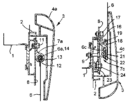
The display apparatus illustrated comprises a light box 1 constructed of
aluminium sections defining a rectangular rim 2 to which a covering frame 3 is
fitted.
The frame 3 is made up of four extruded aluminium sections 4a - d and can be
removed
from the light box to allow mounting and removal of a poster 6.. In an
alternative
embodiment, the upper frame section 4a, or any of the other frame sections,
may be
pivoted to the light box 1, to allow the frame 3 to be tilted away from the
poster.
The display apparatus includes four elongate holding devices 7a - d for
holding
respective edge portions 6a - d of the poster 6. The holding devices are fixed
to
mounting plates 8 which are, in turn, fixed to the rim 2 of the light box 1 by
bolts 9.
The poster 6 is made of reinforced PVC (or any other suitable more or less
resilient
sheet material) and is under tension between the upper and lower holding
devices 7a,7c
and between the lateral holding devices 7b,7d.
The upper holding device 7a comprises a single aluminium section which
extends horizontally and which is fixed to the corresponding mounting plate 8
by a
series of bolts 11 (only one of which is visible in Figure 2). In the
underside of the
holding device 7a there is an undercut slot 12 communicating with a generally
cylindrical internal cavity 13 and accommodating a longitudinal bead 14
constituting
the upper edge portion 6a of the poster. The bead 14 is constructed by turning
the edge
of the sheet material of the poster 6 around a plastics rod (which may be
solid, as
shown, or hollow) and welding (or otherwise fixing) the sheet material to
itself. The
upper edge portion 6a of the poster is a loose fit in the holding device 7a,
so that it can
be slid along the holding device when the poster 6 is not under vertical
tension.
The lower holding device 7c and the left-hand lateral holding device 7d are
similar to each other. Each comprises a fixed bearing member 16 in the form of
an
extruded aluminium section fixed to the corresponding mounting plate 8 by
bolts 17,
and a movable member 18 which is also constituted by an aluminium section. The
movable member 18 is pivotable about a pivot axis 19 relative to the fixed
member 16.
The movable member 18 has a longitudinal recess 21 which is open in a
direction away
from the opposite holding device and which receives the enlarged edge portion
6c or 6d
of the poster 6. The enlarged edge portion is formed by passing the sheet
material of

CA 02468834 2004-05-31
WO 03/049069 PCT/GB02/05392
4
the poster around a plastics strip 22 of generally rectangular cross-section
and welding
(or otherwise fixing) the sheet material to itself. An extension 23 of the
movable
member 18 is releasably connected to the mounting plate 8 by screws 24.
The right-hand lateral holding device 7b is constituted by an extruded
aluminium section which is identical to the movable member 18 but which has
its
extension 23 fixed to the corresponding mounting plate 8 by a series of bolts
26.
To mount the poster 6 in the display apparatus, the bead 14 along the upper
edge
of the poster is fitted into the left-hand end of the undercut slot in the
fixed upper
holding device 7a and is slid along the undercut slot. The enlarged right-hand
edge
portion 6b of the poster 6 is then inserted in the recess 21 in the fixed
holding device 7b.
At this time, the movable member 18 of each of the lower and left hand holding
devices
7c,7d is in the passive position shown in Figure 6B, in which the recess 21 is
open
towards the front. The remaining edge portions 6c and 6d of the poster are
inserted into
the respective recesses 21 of the respective holding devices 7c and 7d. Motion
of each
movable member 18 from the passive position shown in Figure 6B to the active
position
shown in Figure 6A applies tension to the poster 6. Finally, the extensions 23
are
screwed to the mounting plates 8 and the covering frame 3 is fitted on the
light box 1.
To remove the poster 6, the covering frame 3 is removed so as to expose the
edges of the poster, the screws 24 are removed, and each movable member 18 is
pivoted
forward through about 90 (or more) from the active position shown in Figure
6A to the
passive position shown in Figure 6B, in which tension in the poster is
released
sufficiently to allow the edge portions 6c,6d to be removed from the recesses
21. The
right-hand edge portion 6b is then removed from the recess 21 of the right-
hand holding
device 7b, and finally the bead 14 is slid to the left out of the upper
holding device 7a.
In each of the lower and left lateral holding devices 7c,7d the fixed bearing
member 16 has a fixed end portion 16a, an intermediate portion 16b, and a free
end
portion 16c. The intermediate portion 16b has a convex bearing surface 16d,
part of
which is cylindrical. The free end portion 16c has a cylindrical external
bearing surface
16e, which is co-axial with the cylindrical part of the convex bearing surface
16d. The

CA 02468834 2004-05-31
WO 03/049069 PCT/GB02/05392
movable member 18 has longitudinal wings 18a and 18b which define between them
an
open cavity 27 to receive the free end portion 16c and the intermediate
portion 16b.
The wing 18a has a concave cylindrical bearing surface 18d which matches the
cylindrical external bearing surface 16e. The wing 18a is received in a space
28
between the free end portion 16c and the intermediate portion 16b when the
movable
member is in its passive position (Figure 6B). The wing 18b has a concave
surface 18e
which fits against the convex bearing surface 16b when the movable member 18
is in its
active position (Figure 6A). The wings 18a,18b cooperate with the free end
portion 16c
and the intermediate portion 16b so as to prevent separation of the movable
member 18
from the fixed member 16 in any direction transverse to the pivot axis 19.
Various modifications may be made within the scope of the invention. For
example, the right-hand lateral holding device 7b could be a mirror image of
the left-
hand lateral holding device 7b.
The undercut slot 12 in the upper holding device 7a allows the user to support
the poster initially at the top while the lateral position of the poster is
adjusted.
The bearing surfaces 16d, 16e and 18d, 18e cooperate to ensure that no
excessive local stress is applied to the holding devices 7c, 7d by the taut
poster.

Representative Drawing
A single figure which represents the drawing illustrating the invention.
Administrative Status

2024-08-01:As part of the Next Generation Patents (NGP) transition, the Canadian Patents Database (CPD) now contains a more detailed Event History, which replicates the Event Log of our new back-office solution.

Please note that "Inactive:" events refers to events no longer in use in our new back-office solution.

For a clearer understanding of the status of the application/patent presented on this page, the site Disclaimer , as well as the definitions for Patent , Event History , Maintenance Fee  and Payment History  should be consulted.

Event History

Description Date
Time Limit for Reversal Expired 2015-11-30
Letter Sent 2014-12-01
Inactive: Late MF processed 2014-01-08
Letter Sent 2013-11-29
Inactive: Late MF processed 2011-12-28
Letter Sent 2011-11-29
Grant by Issuance 2011-02-22
Inactive: Cover page published 2011-02-21
Letter Sent 2010-12-20
Pre-grant 2010-12-08
Inactive: Final fee received 2010-12-08
Final Fee Paid and Application Reinstated 2010-12-07
Deemed Abandoned - Failure to Respond to Maintenance Fee Notice 2010-11-29
Notice of Allowance is Issued 2010-06-09
Letter Sent 2010-06-09
Notice of Allowance is Issued 2010-06-09
Inactive: Approved for allowance (AFA) 2010-06-01
Amendment Received - Voluntary Amendment 2009-12-16
Inactive: S.30(2) Rules - Examiner requisition 2009-06-25
Amendment Received - Voluntary Amendment 2008-05-07
Letter Sent 2008-01-08
Request for Examination Received 2007-11-14
Request for Examination Requirements Determined Compliant 2007-11-14
All Requirements for Examination Determined Compliant 2007-11-14
Letter Sent 2004-09-08
Inactive: Single transfer 2004-08-11
Inactive: Cover page published 2004-08-03
Inactive: Courtesy letter - Evidence 2004-08-03
Inactive: Notice - National entry - No RFE 2004-07-30
Application Received - PCT 2004-07-02
National Entry Requirements Determined Compliant 2004-05-31
Application Published (Open to Public Inspection) 2003-06-12

Abandonment History

Abandonment Date Reason Reinstatement Date
2010-11-29

Maintenance Fee

The last payment was received on 2010-12-07

Note : If the full payment has not been received on or before the date indicated, a further fee may be required which may be one of the following

  • the reinstatement fee;
  • the late payment fee; or
  • additional fee to reverse deemed expiry.

Patent fees are adjusted on the 1st of January every year. The amounts above are the current amounts if received by December 31 of the current year.
Please refer to the CIPO Patent Fees web page to see all current fee amounts.

Fee History

Fee Type Anniversary Year Due Date Paid Date
MF (application, 2nd anniv.) - small 02 2004-11-29 2004-05-31
Basic national fee - small 2004-05-31
Registration of a document 2004-08-11
2005-10-25
MF (application, 3rd anniv.) - small 03 2005-11-29 2005-10-25
MF (application, 4th anniv.) - small 04 2006-11-29 2006-10-24
2006-10-24
Request for examination - standard 2007-11-14
MF (application, 5th anniv.) - standard 05 2007-11-29 2007-11-15
MF (application, 6th anniv.) - standard 06 2008-12-01 2008-11-25
MF (application, 7th anniv.) - standard 07 2009-11-30 2009-11-30
Reinstatement 2010-12-07
MF (application, 8th anniv.) - standard 08 2010-11-29 2010-12-07
Final fee - standard 2010-12-08
MF (patent, 9th anniv.) - standard 2011-11-29 2011-12-28
Reversal of deemed expiry 2013-11-29 2011-12-28
MF (patent, 10th anniv.) - standard 2012-11-29 2012-10-10
Reversal of deemed expiry 2013-11-29 2014-01-08
MF (patent, 11th anniv.) - standard 2013-11-29 2014-01-08
Owners on Record

Note: Records showing the ownership history in alphabetical order.

Current Owners on Record
URBAN STORM LIMITED
Past Owners on Record
SAM COOK
Past Owners that do not appear in the "Owners on Record" listing will appear in other documentation within the application.
Documents

To view selected files, please enter reCAPTCHA code :


To view images, click a link in the Document Description column. To download the documents, select one or more checkboxes in the first column and then click the "Download Selected in PDF format (Zip Archive)" or the "Download Selected as Single PDF" button.

List of published and non-published patent-specific documents on the CPD .

If you have any difficulty accessing content, you can call the Client Service Centre at 1-866-997-1936 or send them an e-mail at CIPO Client Service Centre.


Document
Description 
Date
(yyyy-mm-dd) 
Number of pages   Size of Image (KB) 
Description 2004-05-30 5 263
Abstract 2004-05-30 2 73
Claims 2004-05-30 3 149
Representative drawing 2004-05-30 1 16
Drawings 2004-05-30 3 65
Description 2008-05-06 7 358
Abstract 2008-05-06 1 19
Claims 2008-05-06 3 141
Description 2009-12-15 7 349
Claims 2009-12-15 3 139
Representative drawing 2011-01-26 1 15
Notice of National Entry 2004-07-29 1 193
Courtesy - Certificate of registration (related document(s)) 2004-09-07 1 128
Reminder - Request for Examination 2007-07-30 1 119
Acknowledgement of Request for Examination 2008-01-07 1 176
Commissioner's Notice - Application Found Allowable 2010-06-08 1 167
Courtesy - Abandonment Letter (Maintenance Fee) 2010-12-19 1 173
Notice of Reinstatement 2010-12-19 1 164
Maintenance Fee Notice 2011-12-27 1 171
Late Payment Acknowledgement 2011-12-27 1 164
Maintenance Fee Notice 2014-01-07 1 170
Late Payment Acknowledgement 2014-01-07 1 163
Maintenance Fee Notice 2015-01-11 1 170
PCT 2004-05-30 3 90
Correspondence 2004-07-29 1 25
Correspondence 2004-08-10 2 66
Correspondence 2010-12-07 1 29
Fees 2010-12-06 2 74