Note: Descriptions are shown in the official language in which they were submitted.
CA 02469136 2004-06-02
WO 2004/028202 PCT/US2003/029637
SLEEVED ULTRASONIC TRANSDUCER
BACKGROUND OF THE INVENTION
Field of the Invention
This invention relates generally to ultrasonic generators, transducers,
and converters, and relates more particularly to an ultrasonic transducer or
converter having a two-piece head mass or front driver, where one piece
provides good thread integrity and the other piece provides good acoustic
and/or
heat transfer properties.
Description of the Relevant Art
Typical prior art stacked ultrasonic transducers or converters 10 and 12
are shown in Figures 1 and 2. Both transducers 10 and 12 have multiple PZTs
14 (piezoelectric crystals or transducers), which are annular in shape and are
located between a tail mass or back driver 16 and a head mass or front driver
18
(Fig. 1) or 20 (Fig. 2). A bolt 22 is threaded into internal threads in the
head
mass 18 or 20 to hold the converter together and to compress the PZTs 14
between the head mass and tail mass. An insulating sleeve 23 electrically
insulates the PZTs 14 from the bolt 22, and electrical contacts 25 provide
electrical connections to the PZTs. A threaded extension 24 connects the
converter to a booster or horn (not shown) used for ultrasonic welding or
similar
application. The PZTs operate in thickness mode, which means they expand
and contract primarily in the direction of the central axis 26 of the
transducer.
The head mass 18 or 20 is tapered in order to amplify the amplitude of the
vibrations of the PZTs 14.
In Figure l, the head mass 18 is a single material such as aluminum or
titanium. Aluminum has an advantage in that it has a high thermal capacity
which is useful as a heat sink for transfernng heat away from the PZTs.
However, aluminum is a relatively soft metal and the screw threads needed to
-1-
CA 02469136 2004-06-02
WO 2004/028202 PCT/US2003/029637
retain the bolt 22 and threaded extension 24 are correspondingly weak.
Titanium has superior material strength and thread strength as compared to
aluminum, but has a lower thermal capacity and cannot absorb heat as
effectively as aluminum.
The transducer 12 shown in Figure 2 substitutes titanium for aluminum
in the threaded area of the head mass. The two-piece head mass 20 is composed
of aluminum in the proximal piece 28 next to the PZTs 14 and is composed of
titanium in the distal piece 30 that contains internal threads to mate with
the
bolt 22 and the threaded extension 24. A disadvantage of such a two-piece head
mass design is that it does not perform as well as a single-piece head mass
(Figure 1) because having two materials interferes with the amplitude gain of
the tapered head mass and the transmission of ultrasonic vibrational energy
from the PZTs to the booster or horn.
In other applications, an ultrasonic transducer may be attached to a
surface to which ultrasonic vibrational energy is to be transferred. For
example,
the surface may be the outside surface of a tank holding a cleaning solution
and
in which objects to be cleaned ultrasonically are immersed. In such an
application, the ultrasonic transducer may be adhesively bonded to the tank
surface. However, if the material of the tank and that of the head mass are
different, there may be a mismatch in the coefficients of thermal expansion,
which can cause failure of the adhesive bond. The tank may be made of quartz
and the head mass of the transducer may be made of aluminum, which have
significantly different coefficients of thermal expansion.
SUMMARY OF THE INVENTION
In summary, the present invention is a sleeved ultrasonic transducer
comprising a threaded sleeve for one part of the head mass and an outer
housing
of a different material for the other part of the head mass. Since the head
mass
is composed of two parts, they can be made of different materials, each
selected
to optimize a different property or function. The threaded sleeve is
preferably
metal such as titanium that provides superior thread strength for mating with
the
bolt and threaded extension, if any, while the outer housing is preferably
_2_
CA 02469136 2006-08-15
52130-1
aluminum or ceramic trat provides good thermal heat sinlc capaciy anc~'or
transmission of vibrational energy. The combination or the two components
protrides an improved ultrasonic transducer.
More specifically, the ultrasonic transducer of the present invention
5 includes one or more dish-shaped piezoelectric crystals, wherein each
piezoelectric crystal has an axial hole; a tail mass positioned on one side ef
the
piezoelectric crystals, uTherein the tail mass includes an axial hole; a head
mass
positioned on a side of the piezoelectric crystals opposite the tail mass,
wherein
the head mass has an internally-threaded a~.ial hole; and a threaded bolt
10 positioned within the a~:ial hole of each piezoelectric crystal and the
axial holes
of the tail mass and head mass and threaded into the internally-tlmeaded axial
hole of the head mass, wherein the bolt compresses the piezoelectric crystals
between the tail mass and head mass. The head mass includes two pieces
composed of different materials, including a tlireaded sleeve that has the
1~ internally-threaded a~:ial hole and has a reduced diameter section and
further
including an outer housing that is axially outside the reduced diameter
section
of the threaded sleeve.
Preferably, the threaded sleeve and the outer housing have matir_g
contact surfaces on a plane perpendicular to an axis of the transducer. Also
20 preferably, an outer diameter of the reduced diameter section of the
threaded
sleeve is substantially equal to an inner diameter of the one or more
piezoelectric crystals.
-3-
CA 02469136 2006-08-15
52130-1
According to an aspect of the invention, there is
provided an ultrasonic transducer, comprising: one or more
disk-shaped piezoelectric crystals, wherein each
piezoelectric crystal has an axial hole; a tail mass
positioned on one side of the piezoelectric crystals,
wherein the tail mass includes an axial hole; a head mass
positioned on a side of the piezoelectric crystals opposite
the tail mass, wherein the head mass has an internally-
threaded axial hole; and a threaded bolt positioned within
the axial hole of each piezoelectric crystal and the axial
holes of the tail mass and head mass and threaded into the
internally-threaded axial hole of the head mass, wherein the
bolt compresses the piezoelectric crystals between the tail
mass and head mass; wherein the head mass includes two
pieces composed of different materials, including a threaded
sleeve that has said internally-threaded axial hole and has
a reduced diameter section and further including an outer
housing having an axial hole that mates with the reduced
diameter section of the threaded sleeve.
According to another aspect of the invention,
there is provided an ultrasonic transducer, comprising: one
or more disk-shaped piezoelectric crystals, wherein each
piezoelectric crystal has an axial hole; a tail mass
positioned on one side of the piezoelectric crystals,
wherein the tail mass includes an axial hole; a head mass
positioned on a side of the piezoelectric crystals opposite
the tail mass, wherein the head mass has an internally-
threaded axial hole; and a threaded bolt positioned within
the axial hole of each piezoelectric crystal and the axial
holes of the tail mass and head mass and threaded into the
internally-threaded axial hole of the head mass, wherein the
bolt compresses the piezoelectric crystals between the tail
mass and head mass; wherein the head mass includes an outer
-3a-
CA 02469136 2006-08-15
52130-1
housing proximal to the piezoelectric transducers and a
threaded sleeve distal to the piezoelectric transducers,
wherein the outer housing has an axial hole with clearance
for the bolt and wherein the threaded sleeve includes the
internally-threaded axial hole that mates with threads on
the bolt, wherein the outer housing and threaded sleeve are
composed of different materials, and wherein the outer
housing has a counterbored hole and the threaded sleeve has
a cylindrical sleeve portion that fits inside the
counterbored hole of the outer housing.
According to a further aspect of the invention,
there is provided an ultrasonic transducer, comprising: one
or more disk-shaped piezoelectric crystals, wherein each
piezoelectric crystal has an axial hole having an inner
diameter; a tail mass positioned on one side of the
piezoelectric crystals, wherein the tail mass includes a
threaded portion disposed within the inner diameter of the
piezoelectric crystals; a head mass positioned on a side of
the piezoelectric crystals opposite the tail mass, wherein
the head mass includes a threaded portion disposed within
the inner diameter of the piezoelectric crystals, and
wherein the threaded portions of the tail mass and head mass
engage and compress the piezoelectric crystals between the
tail mass and head mass.
According to a still further aspect of the
invention, there is provided an ultrasonic transducer,
comprising: one or more disk-shaped piezoelectric crystals,
wherein each piezoelectric crystal has an axial hole; a tail
mass positioned on one side of the piezoelectric crystals,
wherein the tail mass includes an axial hole; a head mass
positioned on a side of the piezoelectric crystals opposite
the tail mass, wherein the head mass has an internally-
threaded axial hole; and a threaded bolt positioned within
-3b-
CA 02469136 2006-08-15
52130-1
the axial hole of each piezoelectric crystal and the axial
holes of the tail mass and head mass and threaded into the
internally-threaded axial hole of the head mass, wherein the
bolt compresses the piezoelectric crystals between the tail
mass and head mass; wherein the head mass includes a
threaded sleeve proximal to the piezoelectric transducers
and an outer housing distal to the piezoelectric
transducers, wherein the threaded sleeve includes the
internally-threaded axial hole that mates with threads on
the bolt, wherein the threaded sleeve and outer housing are
composed of different materials, and wherein the outer
housing has an axial hole and the threaded sleeve has a
sleeve portion that fits inside the axial hole of the outer
housing.
The features and advantages described in the
specification are not all inclusive, and particularly, many
additional features and advantages will be apparent to one
of ordinary skill in the art in view of the drawings,
specification and claims hereof. Moreover, it should be
noted that the language used in the specification has been
principally selected for readability and instructional
purposes, and may not have been selected to delineate or
circumscribe the inventive subject matter, resort to the
claims being necessary to determine such inventive subject
matter. For example, the specification uses the terms
transducer, converter, and generator interchangeably to
refer to a device that generates ultrasonic vibrations in
response to an electrical driving signal. The
-3c-
CA 02469136 2004-06-02
WO 2004/028202 PCT/US2003/029637
term piezoelectric crystal is used interchangeably with the terms
piezoelectric
transducer and PZT. Also, the terms head mass and front driver are used
interchangeably to refer to the portion of the transducer (or converter or
generator) through which the ultrasonic vibrational energy passes to the
object
of interest. Likewise, the terms tail mass and back driver are used
interchangeably to refer to the portion of the transducer (or converter or
generator) that is opposite the head mass (or front driver) and that provides
a
mass to balance the vibrations of the piezoelectric crystals.
BRIEF DESCRIPTION OF THE DRAWINGS
Figure 1 is a side sectional view of a prior art ultrasonic transducer
having a head mass composed of a single metal material.
Figure 2 is a side sectional view of another prior art ultrasonic
transducer, this one having a two piece head mass composed of two metal
materials.
Figure 3 is a side sectional view of a threaded sleeve of the head mass of
a first embodiment of an ultrasonic transducer according to the present
invention.
Figure 4 is a side sectional view of an outer housing of the head mass of
the first embodiment of an ultrasonic transducer according to the present
invention.
Figure 5 is a side sectional view of a sleeved ultrasonic transducer
according to the present invention, which uses the titanium sleeve of Figure 3
and the aluminum housing of Figure 4.
Figure 6 is side view of the sleeved ultrasonic transducer of the
transducer of Figure 5.
Figure 7 is an impedance-frequency chart of a transducer with a two
piece aluminum/titanium front driver as shown in Figure 2.
Figure 8 is an impedance-frequency chart of the first embodiment of a
sleeved ultrasonic transducer according to the present invention.
-4-
CA 02469136 2004-06-02
WO 2004/028202 PCT/US2003/029637
Figure 9 is a side sectional view of another embodiment of a sleeved
ultrasonic transducer according to the present invention, similar to the
transducer of Figures 3-6.
Figure 10 is an alternative embodiment of a sleeved ultrasonic
transducer according to the present invention.
Figure 11 is a side sectional view of another alternative embodiment of a
sleeved ultrasonic transducer according to the present invention.
Figure 12 is a side view the transducer of Figure 11.
Figure 13 is a side sectional view of another alternative embodiment of a
sleeved ultrasonic transducer according to the present invention.
DETAILED DESCRIPTION OF THE PREFERRED EMBODIMENTS
The drawings depict various preferred embodiments of the present
invention for purposes of illustration only. One skilled in the art will
readily
recognize from the following discussion that alternative embodiments of the
structures and methods illustrated herein may be employed without departing
from the principles of the invention described herein.
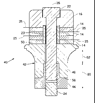
As shown in Figures 3-6, a sleeved ultrasonic transducer 40 according to
the present invention has a two-piece head mass 42 that comprises an
internally-
threaded sleeve 44 of one material and a counterbored outer housing 46 of
another material. Preferably, the threaded sleeve 44 is composed of a
material,
such as titanium or other metal, that has sufficient material strength for
screw
threads. Also preferably, the outer housing is composed of a material, such as
aluminum, another metal, or ceramic or other non-metallic material, that
provides advantageous thermal and/or acoustical properties, including thermal
conduction, thermal expansion and/or efficient conduction of the vibrational
energy generated by the PZTs (piezoelectric transducers or crystals) 14.
The threaded sleeve 44 has internal threads 48 that mate with external
threads of the bolt 22 and the threaded extension 24. The outer housing 46 has
a flat upper surface 50 that contacts the PZT stack and a counter bored hole
52
that nests or mates with a reduced diameter section 54 of the threaded sleeve
44.
The outer housing 46 has a flat lower surface 56 that is perpendicular to the
axis
-5-
CA 02469136 2004-06-02
WO 2004/028202 PCT/US2003/029637
of the transducer and that contacts a shoulder 58 of the threaded sleeve 44.
The
bolt 22 compresses the PZTs 14 against the upper surface 50 of the outer
housing 46 and compresses the lower surface 56 against shoulder 58 of the
threaded sleeve 44. Axial vibrations from the PZTs 14 travel through the outer
housing 46 and into the threaded sleeve 44 at the contact between the surface
56
of the outer housing and the shoulder 58 of the threaded sleeve.
The lower surface 56 of the outer housing 46 is preferably located in a
cylindrical section 60 of the head mass, not in a tapered section 62. The
amplitude gain of the head mass is fully developed in the tapered section 62
so
that the vibrations in the cylindrical section 60 are axial. The transition
between
the two pieces of the head mass, where surface 56 butts against shoulder 58,
is
located at the cylindrical section so that the axial vibrations are
transferred
efficiently from the outer housing 46 to the threaded sleeve 44. Preferably,
the
outer diameter of the reduced diameter section 54 of the threaded sleeve is
substantially the same as the inner diameter of the PZTs 14.
As compared to the prior ultrasonic transducer 12 with a two piece head
mass 20 (Figure 2), the sleeved ultrasonic transducer 40 of the present
invention
with an aluminum outer housing 46 and a titanium threaded sleeve 44 has more
aluminum for better heat sinking and has a more effective transition of
vibrations between the aluminum and titanium pieces. As shown in Figure 7,
the prior transducer 12 has a minimum impedance of 11.24 ohm, while Figure 8
shows that such a sleeved transducer 40 of the present invention has an
improved minimum impedance of 4.18 ohm.
As compared to the prior art one piece ultrasonic transducer 10 (Figure
1), the sleeved ultrasonic transducer 40 of the present invention with an
aluminum outer housing 46 and a titanium threaded sleeve 44 has better thread
strength than an all-aluminum head mass and better thermal heat sinking than
an all-titanium head mass. The combination of the titanium threaded sleeve 44
and aluminum outer housing 46 of the sleeved transducer 40 achieves acoustical
performance equivalent to single-metal front drivers.
The outer housing may also be composed of a metal other than
aluminum or a non-metallic material including ceramics such as silicon
carbide,
-6-
CA 02469136 2004-06-02
WO 2004/028202 PCT/US2003/029637
aluminum oxide, or other advanced ceramics. As used herein, the term
"advanced ceramics" is intended to mean ceramic materials having a minute
grain size of a few microns or a fraction of a micron and which also have very
high density with near zero porosity as measured in microns. The grain
structure is highly uniform allowing ultrasonic signals to move in every
direction simultaneously. Silicon Carbide is a preferred form of advanced
ceramic and is made from a chemical reaction with graphite. Using a ceramic
material for the outer housing improves acoustic performance because ceramic
is a better conductor of ultrasonic vibrational energy than aluminum and other
metals, and may be preferred for that reason.
Figure 9 shows an alternative construction of the Figure 3-6
embodiment of the present invention. Transducer 90 has a head mass 92 that
has an outer housing 94 and a threaded sleeve 96. A reduced diameter section
98 of the threaded sleeve 96 extends upwardly to the top of the outer housing
94. The outer housing 94 has an axial hole sized to accommodate the section 98
of the threaded sleeve 96. Preferably, the outer diameter of the reduced
diameter section 98 of the threaded sleeve 96 is substantially the same as the
inner diameter of the PZTs 14. Vibrational energy from the PZTs 14 is
transferred to the outer housing 94, then downward to a bottom surface 100 of
the outer housing to an upper surface 102 of the threaded sleeve 96. In other
respects, the transducer 90 is the same as the transducer 40 described above.
Figure 10 shows an alternative embodiment of the present invention for
high frequency applications. An ultrasonic transducer 70 has two annular PZTs
72 in the middle of a stack, an annular disk 74 of aluminum oxide above the
PZTs, an annular disk 76 of silicon carbide below the PZTs, a titanium head
mass 78 and a titanium tail mass 80. The tail mass 80 has a threaded sleeve 82
that is internally threaded and that extends into the annular region of the
transducer stack from above. The head mass 78 has an externally threaded
member 84 that extends into the annular region of the transducer stack from
below. The internally threaded sleeve 82 of the tail mass 80 mates with the
externally threaded member 84 of the head mass 78 to secure the transducer
CA 02469136 2004-06-02
WO 2004/028202 PCT/US2003/029637
stack and compress the PZTs 72 and disks 74 and 76 between the head mass
and tail mass.
Another aspect of the present invention relates to an improvement in
ultrasonic transducers used in cleaning systems, shown in Figures 12-13. More
specifically, it has now been recognized that enhanced performance can be
achieved by forming the tank or vessel out of quartz or an advanced ceramic
material and by bonding the transducer directly onto a surface of the tank.
Ultrasonic transducers commonly used for cleaning operations have a
stacked construction. A typical transducer has one or more piezoelectric
crystals shaped in the form of a disk with an annular hole. The piezoelectric
crystal is oriented so that expansion and contraction in response to applied
electrical signals is axial in direction. On one side of the piezoelectric
crystal is
a tail mass and on the other side is a head mass. A screw or bolt compresses
the
piezoelectric crystal between the head mass and tail mass. The head mass is
mounted on the tank and transmits vibrations from the piezoelectric crystal to
the tank. The tail mass balances the displacements caused by the expansion and
contraction of the piezoelectric crystal. In my prior U.S. Patents 5,748,566
and
5,998,908, I disclosed an improvement to a stacked transducer construction,
which added a resonator made of a ceramic material between the piezoelectric
crystal and the head mass.
One problem to overcome in bonding a transducer to a cleaning tank is
inconsistent material properties between the materials used for the tank and
transducer. Head and tail masses are commonly made from metals, such as
aluminum, which have a much higher coefficient of expansion than quartz or
ceramics such as silicon carbide.
The present invention has a different construction for the transducer,
which facilitates bonding of the transducer to a tank. Typically more than one
transducer is mounted to a tank, either internally or externally. Commonly
several transducers are mounted to the bottom of a cleaning tank. The tank
contains a liquid and parts to be cleaned, rinsed, or otherwise processed
using
ultrasonics. The transducers are excited by an alternating current. Vibrations
_g_
CA 02469136 2004-06-02
WO 2004/028202 PCT/US2003/029637
caused by the piezoelectric crystals of the transducers are transferred into
the
tank and through the liquid to the parts in the tank.
The construction of another embodiment of the transducer of the present
invention is shown as transducer 110 in Figures 11 and 12. The components of
the transducer 110, from the top, include a tail mass 118, electrode 120,
piezoelectric crystal 122, electrode 120, ceramic resonator 124, and a head
mass
125 that includes a threaded sleeve 126 and an outer housing 128. A bolt 130
is
threaded into an internally threaded hole in the threaded sleeve 122 and
compresses the electrodes 120, piezoelectric crystal 122 and ceramic resonator
124 between the tail mass 118 and the head mass 125. The outer housing 128 is
preferably composed of silicon carbide or other ceramic material and is bonded
to a flat surface 132 of the threaded sleeve 126. Preferably, the outer
housing is
composed of a metal or non-metallic material that has a coefficient of thermal
expansion that is similar to the coefficient of thermal expansion of the
material
of the tank. Another flat surface 134 of the outer housing 128 is bonded to a
surface of a cleaning tank. A protrusion 136 at the bottom of the threaded
sleeve 126 mates with an axial hole 138 of the outer housing 128 to assist in
positioning the threaded sleeve relative to the outer housing. All the parts
of the
transducer except the electrodes 120 are axially symmetrical. The tail mass
118
and threaded sleeve 126 are preferably composed of aluminum material, but
may be made of other non-metallic materials or metals such as titanium if
thread strength is an issue.
An alternative construction of the transducer 110 is shown in Figure 13.
Transducer 150 has a threaded sleeve 152 that extends downward to the bottom
of the outer housing 128, which provides more thread area for the bolt 130 to
engage. Also, transducer 150 has an insulated sleeve 154 inside the inner
diameter of the PZT 156. Preferably, the outer diameter 158 of the lower
protrusion 160 of the threaded sleeve 152 is substantially the same as the
inner
diameter 162 of the PZT 156. Such a construction may be more efficient in
transferring the vibrational energy of the PZT through the outer housing 128
to
the tank. Alternatively, the ceramic resonator 124 may have the same inner
_g_
CA 02469136 2004-06-02
WO 2004/028202 PCT/US2003/029637
diameter as the PZT 156 with the insulated sleeve 154 extending downward to
the top of the threaded sleeve 152.
One advantage of the construction of transducer 110 or 150 is that the
outer housing 128 of the head mass can be made out of a metal or non-metallic
material, such as silicon carbide, that has properties similar to those of the
tanle
material, which may be quartz or silicon carbide or other advanced ceramic.
Silicon carbide is a polycrystalline material. There are many grains in a
silicon
carbide ceramic, with grain size being a few micrometers (direct sintered).
There are different forms of quartz, including fused quartz and single crystal
quartz. Fused quartz is an amorphous (non-crystalline, or glass) material.
Generally speaking, single crystal quartz is one big grain. It can be as big
as
several inches (with only one grain). Fused quartz is amorphous, so it does
not
contain any grains.
The coefficients of thermal expansion of glass and ceramic are isotropic,
meaning that it is not direction dependent. The coefficient of thermal
expansion
of a single crystal quartz is anisotropic (direction dependent), meaning it
varies
with the crystal orientation. Generally speaking, the coefficient of thermal
expansion of quartz single crystal is about 15-20 times bigger than fused
quartz
glass. The preferred type of quartz for cleaning tanks is fused quartz. The
coefficients of thermal expansion (in units of ~m/m-°C) are 0.4 for
fused quartz,
4.5 for silicon carbide, 17 for stainless steel, 9 for titanium, and 23-24 for
aluminum.
By using silicon carbide instead of aluminum for the portion of the head
mass that is bonded to a cleaning tank, the thermal mismatch is reduced
significantly. The mismatch in thermal expansion between two bonded
materials induces stresses within the material/boundary when there is a
temperature change. The difference in thermal expansion coefficients between
aluminum and fused quartz is about 60 times, compared to 10 times between
silicon carbide and fused quartz.
The transducer 110 or 150 is bonded to a surface (exterior or interior) of
the tank with an epoxy polymer adhesive Supreme lOAOHT. This epoxy
contains a ceramic filler of aluminum oxide (alumina). It is a heat curing
epoxy
-10-
CA 02469136 2004-06-02
WO 2004/028202 PCT/US2003/029637
with high shear strength and high peel strength. It also is thermally
conductive
and resistant to severe thermal cycling. The same adhesive is used to bond the
silicon carbide outer housing 128 to the aluminum threaded sleeve 126 or 152.
The use of silicon carbide in the head mass provides an ultrasonic
transducer that can readily be bonded to a quartz or ceramic tank, which
facilitates efficient transfer of ultrasonic vibrations from the transducer to
the
parts or items in the tank.
From the above description, it will be apparent that the invention
disclosed herein provides a novel and advantageous sleeved ultrasonic
transducer. The foregoing discussion discloses and describes merely exemplary
methods and embodiments of the present invention. As will be understood by
those familiar with the art, the invention may be embodied in other specific
forms without departing from the spirit or essential characteristics thereof.
Accordingly, the disclosure of the present invention is intended to be
illustrative, but not limiting, of the scope of the invention, which is set
forth in
the following claims.
-11-