Note: Descriptions are shown in the official language in which they were submitted.
CA 02469326 2004-05-28
1 TITLE: SINGLE P~4SS CRUSHING FLOWSHEET
2
3 INTRODUCTION AND PRIOR ART
4
fn the field of mining the technology of oil-sand recovery and processing is
unique to the
6 deposits found in Northern Alberta, Canada in terms of the evolution of
process logic
7 and equipment suitable for mining and processing the oil-sand ore. 1n the
oil-sand mine,
8 equipment used to excavate and transportthe run-of-mine (ROM) oil-sand ore
is as
9 large in scale as at any world-wide mining operations, typically using
electric-hydraulic
shovels of up to 62 cubic metre capacity buckets loading into haulage trucks
of up to 400
11 tonnes capacity to transport the ROM oi!-sand ore to a centralized oil-sand
slurry
12 preparation facility.
14 Due to the massive scale of the mining equipment and the-characteristics of
the oil-sand
itself; the ore received from the mining operation typically contains a very
large range of
16 lump sizes spanning from 3,500 mm arid weighing up to 30 tonnes down to
sand
17 particles of a few millimeters. The ROM on: typically contains up to 306
moisture, 2°!0
18 to 18% bitumen and 45°~o to 55% sand content by weight and also
contains amounts of
19 siltstone rock having an unconfined compressive strength of 165 to 221 MPa
as a Waste
component.
21
22 The harsh environmental conditions at oit-sand operations encompass an
ambient
23 temperature range from +35 degrees Celsius down to -51 degrees Celsius. All
mining
24 and shiny preparation equipment is required to function with unhindered
effectiveness
and productivity under these ambient conditions. Mater7afs handling properties
of the
26 ROM ore are highly variable over this temperature range. The oil-sand ore
comprises
27 frozen, highly abrasive lumps in winter but exhibits sticky, cohesive
behaviour in summer,
28 largely due to the infiluence of the contained moisture and bitumen
components in the
29 particulate matrix.
31 Although it has been demonstrated that oil sand lump size can be reduced
and oil or
32 bitumen can be liberated under the combined influences of mechanical
agitation in
33 intimate contact with water, especially heated water, the practical and
effective
34 implementation of such a process in full scale apparatus suited to the
mining
2!8
CA 02469326 2004-05-28
1 environment has not been achieved. It wilt be clear to one practiced in the
art, however,
2 that any siltstorfe component in the ROM ore carries na economic value and
will be
3 unaffected by mixing with water. The slurry preparation process would
therefore benefit
4 if the siltstone component could be removed from the oil sands and water
mixture by
alternate means for separate handling and disposal.
7 The slurry preparation process step is typically required to prepare all ROM
ore to be
8 suitable for tong-distance transport as a water-based slurry to a remote
upgrading facility,
9 at single-stream production rates exceeding 10,000 tonnes per hour of 'ROM
oil-sand.
Typical prerequisites for efficient slurry pumping are crushing the oil-sand
ore to minus
11 100 mm followed by the preparation of a homogeneous water slurry, typically
with a
12 consistency of about 64°lo solids by weight at a specific gravity of
1.5.
13
14 Current practice for oil-sand slurry preparation in the industry requires
the use of multiple
series-wise equipment processing steps to accomplish controlled ore feeding,
screening
16 and crushing prior to slurry pipelining. Designers and equipment vendors
are challenged
17 to create a facility containing multiple items of processing equipment with
intermediary
18 conveying transfer stages bath for the harsh environment and the high
production rates.
19 The oil-sand slung preparation eguipment is typically housed within large,
structural
steel modules iocat~i within the active oil-sand mining area. These modules
must be
21 constructed suitably for re-locaticm on atypical frequency of 1 to 3 years
per operating
22 location.
23
24 Disadvantages of the prior art fior oil-sand slung preparation arise
largely from
practitioners attempting to adapt conventional process equipment and
conventional
26 process fiowsheet logic to the Canadian oil and context. Canadian patent
Number CA
27 2195604 by Maciejewski et al describes "a vertically oriented stack of
components,
28 (which) functions to slurry oil sand with water in preparat;on for pumping
through a
29 pipeline". Although this patent describes process steps including water
addition and
tumbling of the oil sands ore and water through a vertically oriented
arrangement of
31 baffles, the equipment stack would be overly tall with limited
effectiveness due to the
32 limited and uncontrolled residence time of the oil sand contacting the
water. Similarly,
33 Canadian patenfi number CA 2235938 by Doucet et al describes "an apparatus
for
34 preparing a pumpabte oil sand and water slung (which) comprises a
rotatable: vessel
3f8
CA 02469326 2004-05-28
1 having a perforated tubular wall... ". This example of prior art is
patterned ort the well-
2 known conceptof the "Bradley Breaker" which is essentially a rotary screen
arranged to
3 alternately lift and drop lumps of a material to achieve a simultaneous
crushing action
4 and a screening action. This prior art similarly lacks both controlled
residence time and
intimate contact with the water, as the water will preferentially drain away
from contact
6 with the oil sands lumps immediately upon entering the perforated rotating
vessel. The
7 prior art can therefore be characterized as "process flowsheet deficient"
with respect to
8 inherent limitations in meeting modern oil-sand mining plant requirements in
a practical
9 and efficient manner.
11 The preferred embodiment of this invention comprises a unique and effective
series-wise
12 combination of ~ntinuaus process steps comprising feeding water and oil
sand into a
13 mixing drum motivated to rotate about a substantially horizontal axis, in
which the
14 combined steps of mixing, tumbling and heating the oil sands in a water
bath during a
controlled residence time are effective both in; breaking down lumps of the
ore into
16 smaller sized pieces and in liberating the contained bitumen from the
particulate
17 components of the oil sands ore. These process flowsheet improvements
beneficially
18 impact the design of the slung preparation plant and also facilitate design
for re-location
19 of the slung preparation plant facility.
21
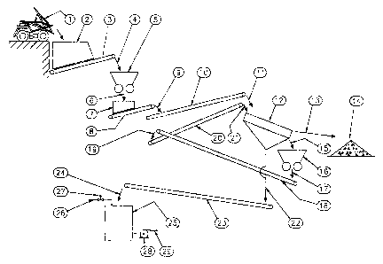
22 With reference to the Figures:
23 Figure 1 is a conventional oil-sand slung preparation plant process
flowsheet illustrating
24 best practices of the prior art for size reduction of the oil sand ore for
a subsequent slurry
preparation process step for pumping the oil sand slurry to a remote upgrading
facility.
27 Figure 2 is a detailed llustration of the slurry preparation step of Figure
1 following the
28 crushing and screening and materials handling steps,
29
In Figure 1, haulage truck 1 dumps RQM oil-sand into receiving hopper 2 from
which
31 reclaim conveyor 3 withdraws oil-sand and feeds it via chute 4 to primary
conventional
32 crusher 5. The primary crushed oil-sand passes through chute 6 to second
receiving
33 hopper 7 from which reclaim conveyor 8 withdraws oif-sand and feeds it via
chute 9 to
34 conveyor 10 feeding via chute 11-° to mufti-deck screen 12. Oversize
rejects from screen
4I8
CA 02469326 2004-05-28
1 12 feed via chute 13 for storage in rejects pile,14. Oversize oi!-sand from
screen 12
2 feeds via chute 15 to secondary conventional crusher 16. The secondary
crushed oil-
3 sand passes through chute 17 to conveyor 18 to chute 19 and conveyor 20 to
feed oil-
4 sand via chute 21 back onto screen 12 in a closed circuit re-handling loop.
Undersize
from screen 12 feeds via chute 22 to conveyor 23 and chute 24 to tank; 25;
tank 25
6 representing a simplified oil-sand slung preparation circuit. Water addition
26 controlled
7 by valve 27 is also added to tank 25 feeding slurry pump 28 delivering oil-
sand lurry
8 through pipeline 29 to a remote facility (not shown). The primary and
secondary
9 flowsheet crushing steps illustrated in Figure 1 could, alternately, be
simplified to having
only one or no crushing steps or to having no internal oil sands recirculation
and
11 screening steps.
12
13 In Figure 2 oil sand is delivered from conveyor 23 through chute 24 into
mixing drum 30.
14 Water addition 26 into chute 24 begins to mix very crudely with the oil
sands dre in the
chute, but subsequently achieves intimate and sustained contact with the oil
sands
16 inside the mixing drum, where raduced diameters at the entry and discharge
ends of the
17 drum forma substantial pool or bath to be retained internally of the drum.
The rotation
18 of the drum causes alternate lifting and falling and tumbling of the
mixture of oil sands
19 and water, assisted by the internal fitment of various kinds of baffles or
lifters or spirals
as are known in the art for the purposes of increasing internal shear forces
in the mixture,
21 increasing the lifting and falling effects and assisting to transport the
mixture towards the
22 discharge end. Mixing drum 30 may also be siigh~y inclined, either to
assist or to retard
23 the transporting of the initial feed mixture from the #eed end of,the drum
towards the
24 discharge end where it discharges onto screen 31. Oversize oil sand lumps
discharge
from the screen to chute 32 feeding conveyor 33 going, alternatively, to a
refuse dump
26 or to be recycled back to a prior crushing step. Undersize from the screen
is permitted
27 direct entry into slung tank 25, where it undergoes further agitation and
density rimming
28 as appropriate prior to entering a pump suction nozzle located at the
bottom of the tank,
29 for the purpose of being pumped to a remote bitumen upgrading plant.
31 Pre-heating of the water entering at 26 is known to improve the liberation
of bitumen
32 from the oil sands particulate matrix; as does the additional meat
generated by the direct
33 conversion of mechanical kinetic energy into heat energy internally of the
drum within
34 the water and oil sand mixture.
5r$
CA 02469326 2004-05-28
1
2 The simplified oil sand slurry preparation arcuit associated with tank 25 of
Figure 1 could
3 also represent any "subsequent process step" of any ore preparation plant
whefiher or
4 not it involves the preparation of a pumpable slung. An alternate subsequent
process
step, for example, may be a milling and grinding process step in which lump
size
6 received from the ore preparation p~antwill still be required to be closely
controlled.
7
8 A preferred means to achieve a controlled density of the oil sand slurry is
to proportion
9 the addition rate of the water according to the mass flow rate of the oil
sand. With
reference to Figure 1 it is clear that the oi( sand rate entering the slurry
preparation step
11 could be measured with a conventional belt weightometer {not shown)
installed on
12 conveyor belt 23. Similarly, water in-flow rate at (ine 26 could be
controlled by valve 27
13 operating in closed loop feedback from a measurecrrent sensor for water
flow rate {not
14 shown). In this way the ultimate density of the oil sand slurry can be
controlled in the
slurry preparation step.
16
17 It will be clear to one practiced in the art that means to remove tramp
metal such as a
18 conventional belt magnet must be provided. Although not shown on the
figures his
19 tramp metal removal means is understood to be present on at least one of
the conveyors
on the flowsheet.
6/8