Note: Descriptions are shown in the official language in which they were submitted.
CA 02469520 2004-06-O1
WO 03/059568 PCT/US03/00686
METHOD FOR LASER MACHINING A WORKPIECE WITH LASER SPOT ENLARGEMENT
Technical Field
[0001] The present invention relates to laser micromachining and, in
particular, to a
method and apparatus employing an fast steering mirror to move a laser spot
having a
focused spot size in a desired pattern on a substrate to remove a target area
that is larger
than the focused spot size on the substrate.
Background of the Invention
[0002] The background is presented herein only by way of example to multilayer
electronic work pieces, such as integrated-circuit chip packages, multichip
modules
(MCMs) and high-density interconnect circuit boards, that have become the most
preferred
components of the electronics packaging industry.
[0003] Devices for packaging single chips such as ball grid arrays, pin grid
arrays,
circuit boards, and hybrid microcircuits typically include separate component
layers of
metal and an organic dielectric and/or reinforcement materials, as well as
other new
materials. Much recent work has been directed toward developing laser-based
micromachining techniques to form vias in, or otherwise process, these types
of electronic
materials. Vias are discussed herein only by way of example to micromachining
and may
take the form of complete through-holes or incomplete holes called blind vial.
Unfortunately, laser micromachining encompasses numerous variables including
laser
types, operating costs, and laser- and target material-specific operating
parameters such as
beam wavelength, power, and spot size, such that the resulting machining
throughputs and
hole quality vary widely.
1
CA 02469520 2004-06-O1
WO 03/059568 PCT/US03/00686
[0004] Pulsed ultraviolet (UV) lasers currently used in micromachining
operations
produce relatively small spot sizes compared to the kerf widths and hole
diameters desired
for many applications. Laser machining throughput for creation of such feature
geometries
that are large compared to the laser spot size, hereinafter referred to as
"contoured
machining," may be increased by employing a larger and lower power density
laser beam.
As described in U.S. Pat. No. 5,841,099, by operating the laser out of focus,
Owen et al.
can effectively enlarge the laser spot size and reduce its energy density.
U.S. Pat. No.
5,593,606 and U.S. Pat. No. 5,841,099, both of Owen et al. describe advantages
of
employing UV laser systems to generate laser output pulses within advantageous
parameters
to form vias or blind vias in multilayer devices. These patents mention well
known
techniques in which vias having diameters larger than that of the focused spot
size may be
produced by trepanning, concentric circle processing, or spiral processing.
These
techniques will hereinafter be collectively referred to as "contoured
drilling."
[0005] Unfortunately, operating the laser out of focus often results in
unpredictable and
undesirable energy distribution and spot shape and adversely impacts via
quality, including
the via wall taper, the degree of melting of the copper layer at the bottom of
the via, and
the height of the "run" around the periphery of the via caused by the splash
of molten
copper during drilling. Furthermore, because the spot size entering
conventional
collimating and focusing optics is inversely proportional to the spot size
impacting the
target, the power density applied to the optics quickly exceeds the damage
threshold of the
optics.
[0006] U.S. Pat. No. 4,461,947 of Ward discloses a method of contoured
drilling in
which a lens is rotated within a plane perpendicular to an incident laser beam
to affect a
target area that is greater in size than that of the focused laser spot. The
lens rotation is
independent of the position of the supporting mounting arm. Ward also
discloses a prior art
method of contoured drilling that relies on movement of the mounting arm
within a plane to
effect lens rotation. In the background, Ward discloses that the beam may be
rotated by a
rotating mirror.
[0007] U.S. Pat. No. 5,571,430 of Kawasaki et al. discloses a laser welding
system that
employs a concave condensing mirror that is pivotal about a first axis and
supported by a
rotary support member on a bearing such that the mirror is rotatable about a
second axis
2
CA 02469520 2004-06-O1
WO 03/059568 PCT/US03/00686
perpendicular to the first axis. The mirror is oscillated about the first axis
to increase the
"width" of target removed and rotated about the second axis to create an
annular pattern.
Summary of the Invention
[0008] An object of the present invention is, therefore, to provide a method
or
apparatus for quickly spatially spreading out the focused laser spots, and
therefore the
energy density, of high repetition rate laser pulses.
[0009] Another object of the invention is rapidly create geometric features
having '
dimensions greater than those of the focused laser spot.
[0010] A further object of the invention is to improve the throughput and/or
quality of
work pieces in such laser machining operations.
[0011] U.S. Pat. Nos. 5,751,585 and 5,847,960 of Cutler et al. and U.S. Pat.
No.
6,430,465 B2 of Cutler include descriptions of split-axis positioning systems,
in which the
upper stage is not supported by, and moves independently from, the lower stage
and in
which the work piece is carried on one axis or stage while the tool is carried
on the other
axis or stage. These positioning systems have one or more upper stages, which
each
support a fast positioner, and can process one or multiple work pieces
simultaneously at
high throughput rates because the independently supported stages each carry
less inertial
mass and can accelerate, decelerate, or change direction more quickly than can
those of a
stacked stage system. Thus, because the mass of one stage is not carried on
the other stage,
the resonance frequencies for a given load are increased. Furthermore, the
slow and fast
positioners are adapted to move, without necessarily stopping, in response to
a stream of
positioning command data while coordinating their individually moving
positions to
produce temporarily stationary tool positions over target locations defined by
the database.
These split-axis, multirate positioning systems reduce the fast positioner
movement range
limitations of prior systems while providing significantly increased tool
processing
throughput and can work from panelized or unpanelized databases.
[0012] Although such split-axis positioning systems are becoming even more
advantageous as the overall size and weight of the work pieces increase,
utilizing longer
and hence more massive stages, they may not provide sufficient bandwidth to
effectively
spread out the energy by large geometric spacing between the laser pulses at
high pulse
repetition frequencies (PRFs).
3
CA 02469520 2004-06-O1
WO 03/059568 PCT/US03/00686
[0013] The present invention employs, therefore, an fast steering mirror, such
as a
piezoelectrically controlled mirror, in the beam path to continuously move the
laser beam in
a high speed prescribed pattern about a nominal target position to spatially
separate the
focused laser spots generated at a high laser repetition rate and thereby
create geometric
features having dimensions greater than those of the focused laser spot. The
invention
permits a series of laser pulses at a given repetition rate to appear as a
series of larger
diameter pulses at a lower pulse rate without the beam quality problems
associated with
working out of focus.
[0014] Additional objects and advantages of this invention will be apparent
from the
following detailed description of preferred embodiments thereof which proceeds
with
reference to the accompanying drawings.
Brief Description of the Drawings
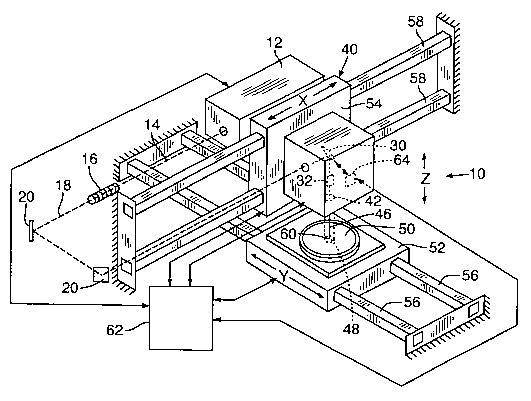
[0015] FIG. 1 is a partly isometric and partly schematic view of a simplified
laser
system incorporating fast steering mirror in accordance with present
invention.
[0016] FIG. 2 is a partly pictorial and partly schematic view of an fast
steering mirror
mechanism employed in the laser system of FIG. 1.
[0017] FIG. 3 is a partly sectional and partly schematic view of an fast
steering mirror
mechanism employed in the laser system of FIG. 1.
[0018] FIG. 4 is a frontal view of the fast steering mirror demonstrating how
mire or
flexion can affect the position of the laser spot.
[0019] FIG. 5 is computer model of an exemplary straight line kerf forming
profile
enhanced by movement of an fast steering mirror in accordance with the present
invention.
[0020] FIG. 6 is computer model of an exemplary via drilling profile enhanced
by
movement of an fast steering mirror in accordance with the present invention.
Detailed Description of Preferred Embodiment
[0021] With reference to FIG. 1, an exemplary embodiment of a laser system 10
of the
present invention includes Q-switched, diode-pumped (DP), solid-state (SS)
laser 12 that
preferably includes a solid-state lasant. Skilled persons will appreciate,
however, pumping
sources other than diodes, such as a krypton arc lamp, are also available. The
pumping
diodes, arc lamp, or other conventional pumping means receive power from a
power supply
(not shown separately) which may form part of laser 12 or may be positioned
separately.
4
CA 02469520 2004-06-O1
WO 03/059568 PCT/US03/00686
[0022] The exemplary laser 12 provides harmonically generated laser output 14
of one
or more laser pulses having primarily a TEMoo spatial mode profile. Preferred
laser
wavelengths from about 150 nanometers (nm) to about 2000 nm include, but are
not limited
to, 1.3, 1.064, or 1.047, 1.03-1.05, 0.75-0.85 microns (~,m) or their second,
third, fourth,
or fifth harmonics from Nd:YAG, Nd:YLF, Nd:YVOa, Nd:YAP, Yb:YAG, or
Ti:Sapphire
lasers 64. Such harmonic wavelengths may include, but are not limited to,
wavelengths
such as about 532 nm (frequency doubled Nd:YAG), 355 nm (frequency tripled
Nd:YAG),
266 mn (frequency quadrupled Nd:YAG), or 213 nm (frequency quintupled Nd:YAG).
Lasers 12 and harmonic generation techniques are well known to skilled
practitioners.
Details of one exemplary laser 12 are described in detail in U.S. Pat. No.
5,593,606 of
Owen et al. An example of a preferred laser 12 includes a Model 210 UV-3500
laser sold
by Lightwave Electronics of Mountain View, California. Skilled persons will
appreciate
that lasers emitting at other suitable wavelengths are commercially available,
including fiber
lasers, or Q-switched COa lasers, and could be employed. An exemplary Q-
switched CO~
laser is disclosed in U.S. Pat. Pub. No. US 2002/0185474 A1 of Dunsky et al.
published
on December 12, 2002.
[0023] With reference to FIG. 1, laser output 14 may be manipulated by a
variety of
well-known optics including beam expander lens components 16 that are
positioned along
beam path 18 before being directed by a series of beam-directing components 20
(such as
stage axis positioning mirrors), fast steering mirror FSM (30), and fast
positioner 32 (such
as a pair of galvanometer-driven X- and Y- axis mirrors) of beam positioning
system 40.
Finally, laser output 14 is passed through a objective lens 42, such as a
focusing or
telecentric scan lens, before being applied as laser system output beam 46
with laser spot 48
at work piece 50.
[0024] A preferred beam positioning system 40 is described in detail in U.S.
Pat., No.
5,751,585 of Cutler et al. and may include ABBE error correction means
described in U.S.
Pat. No. 6,430,465 B2 of Cutler. Beam positioning system 40 preferably employs
a
translation stage positioner that preferably controls at least two platforms
or stages 52 and
54 and supports positioning components 20 to target and focus laser system
output beam 46
to a desired laser target position 60. In a preferred embodiment, the
translation stage
positioner is a split-axis system where a Y stage 52, typically moved by
linear motors,
supports and moves work piece 50 along rails 56, an X stage 54 supports and
moves fast
CA 02469520 2004-06-O1
WO 03/059568 PCT/US03/00686
positioner 32 and objective lens 42 along rails 58, the Z dimension between
the X and Y
stages is adjustable, and beam-directing components 20 align the beam path 18
through any
turns between laser 12 and FSM 30. A typical translation stage positioner is
capable of a
velocity of 500 mmlsec and an acceleration of 1.5 G. For convenience, the
combination of
the fast positioner 32 and one or more translation stages 52 and/or 54 may be
referred to as
a primary or integrated positioning system.
[0025] Beam positioning system 40 permits quick movement between target
positions
60 on the same or different circuit boards or chip packages to effect unique
or duplicative
processing operations based on provided test or design data. An exemplary fast
positioner
is capable of a velocity of 400 or 500 mm/sec and an acceleration of 300 or
500 G, and
hence these are also the typical capabilities of an exemplary integrated
positioning system.
An example of a preferred laser system 10 that contains many of the above-
described
positioning system components is a Model 5320 laser system or others in its
series
manufactured by Electro Scientific Industries, Inc. (ESI) in Portland, Oregon.
Skilled
persons will appreciate, however, that a system with a single X-Y stage for
work piece
positioning and a fixed beam position and/or stationary galvanometer for beam
positioning
may alternatively be employed.
[0026] A laser system controller 62 preferably synchronizes the firing of
laser 12 to the
motion of stages 52 and 54 and fast positioner 32 in a mamler well known to
skilled
practitioners. Laser system controller 62 is shown generically to control fast
positioner 32,
stages 52 and 54, laser 12, and FSM controller 64. Skilled persons will
appreciate that
laser system controller 62 may include integrated or independent control
subsystems to
control and/or provide power to any or all of these laser components and that
such
subsystems may be remotely located with respect to laser system controller 62.
Laser
system controller 62 also preferably controls the movement, including
direction, tilt angles
or rotation, and speed or frequency, of FSM 30, either directly or indirectly
through a
mirror controller 64, as well as controls any synchronization with laser 12 or
components
of positioning system 40. For convenience, the combination of FSM 30 and
mirror
controller 62 may be referred to as the secondary or nonintegrated positioning
system.
[0027] The parameters of laser system output beam 46 are selected to
facilitate
substantially clean, sequential drilling, i.e., via formation, in a wide
variety of metallic,
dielectric, and other material targets that may exhibit different optical
absorption, ablation
6
CA 02469520 2004-06-O1
WO 03/059568 PCT/US03/00686
threshold, or other characteristics in response to IJV or visible light.
Exemplary
parameters of laser system output include average energy densities greater
than about 120
microJoules (,uJ) measured over the beam spot area, preferably greater than
200 ,uJ; spot
size diameters or spatial major axes of less than about 50 ~,m, and preferably
from about 1-
50 ~,m, and typically from about 20-30 ~,m; a repetition rate of greater than
about 1
kiloHertz (kHz), preferably greater than about 5 kHz, and most preferably even
higher than
20 kHz; and a wavelength preferably between about 150-2000 nm, more preferably
between about 190-1325 nrn, and most preferably between about 266 nm and 532
nm. The
preferred parameters of laser system output beam 46 are selected in an attempt
to
circumvent certain thermal damage effects by utilizing temporal pulse widths
that are
shorter than about 100 nanoseconds (ns), and preferably from about 0.1
picoseconds (ps) to
100 ns, and more preferably from about 1-90 ns or shorter. Skilled persons
will appreciate
that these parameters will vary and can be optimized for the material to be
processed, and
that different parameters may be used to process different target layers.
[002] Laser system output beam 46 preferably produces a spot area 48 of a
diameter of
less than about 25-50 ~,m at beam position 60 on work piece 50. Although spot
area 48 and
diameter generally refer to 1/e2 dimensions, especially with respect to the
description of
laser system 10, these terms are occasionally used to refer to the spot area
or diameter of
the hole created by a single pulse. Skilled persons will also appreciate that
the spot area 48
of output beam 46 is generally circular, but may be shaped to be substantially
square.
Skilled persons will also appreciate that output beam 46 can be imaged or
clipped of its
wings or tails, particularly for first step processing, if desired for
specific operations.
[0029] Fig. 2 shows a preferred embodiment of an FSM 30 that is positioned to
receive
laser output 14, deflect it through fast positioner 32, through objective lens
42 to a target
position 60 on work piece 50 for the purpose of ECB via drilling, circuit
element trimming,
or other micro-machining applications. FSM 30 is preferably implemented as
part of a
limited deflection beam positioning stage employing electrostrictive actuators
having a
higher frequency response than the fast positioner 32. FSM 30 is deflected by
ferroelectric
ceramic actuator material, such as lead magnesium niobate (PMN), actuators 22
that
translate voltage into displacement. PMN material is similar to the more
common
piezoelectric actuator material but has less than 1 percent hysteresis, high
electromechanical
conversion efficiency, exhibits wide operating and manufacturing temperature
ranges, does
7
CA 02469520 2004-06-O1
WO 03/059568 PCT/US03/00686
not require permanent polarization, and provides useful mechanical activity
with small
electrical drive voltages.
[0030] Exemplary PMN actuators 22 have a limited displacement of about 20
microns
for a 40 mm long cylinder of PMN material, but have a very high stiffness of
about 210
Newtons per micron for a 5 mm diameter cylinder. FSM 30 is coupled through a
flexure
to three PMN actuators 22 having first ends arranged as an equilateral
triangle having its
center aligned with a center 24 of FSM 120. The second ends of PMN actuators
22 are
mechanically coupled to a mount 26 that attaches to X-axis translation stage
54. The three
PMN actuators 22 are preferably implemented in a 3-degree of freedom
configuration that
is used in a 2-degree of freedom mode to tilt and tip FSM 30. The three PMN
actuators 22
are preferably formed as a hollow cylinder of PMN material that is
electrically
circumferentially divided into three active regions. Activating a region
causes it to expand
or contract, thereby tipping or tilting FSM 30.
[0031] Preferably the actuator triangle has 5 mm sides such that FSM 30 can be
deflected at about a ~4 milliRadian ("mRad") angle, which translates into a ~
640 micron
deflection of laser output 14 when projected onto work piece 50 with an 80 mm
objective
lens 42. An exemplary FSM 30 may provide a typical range of travel limit that
limits the
pattern dimension to up to about 25 or 50 times the laser spot size; however,
a the
maximum frequency response of the FSM 30 may be a more constraining limit that
limits
the pattern dimension to up to about 15 times the laser spot size, and
typically up to 5 to 10
times the laser spot size. FSM 30 operates at higher frequencies and
accelerations than
exemplary galvanometer-driven X- and Y- axis mirrors of fast positioner 32. An
exemplary FSM 30 of the nonintegrated positioning system provides velocities
of greater
than 1,000 mm/sec and may be capable of velocities of 4,000 mm/sec or higher,
which are
to 10 times the velocity of the typical integrated positioning system. An
exemplary FSM
30 of the nonintegrated positioning system provides accelerations of greater
than 1,000 G
and may be capable of accelerations of 30,000 G or greater, which are 50 to
100 times the
acceleration of the typical integrated positioning system.
[0032] ~ In particular, exemplary PMN actuator s 22 have about a 2.0 microFar
ad
characteristic capacitance, 1.0 ohm DC impedance, 17 ohms impedance at 5 kHz,
and
draws over three amperes of current at 75 volts of drive. The exemplary PMN
actuator 22
driving FSM 30 has a large-signal bandwidth greater than about 5 kHz, a small-
signal
8
CA 02469520 2004-06-O1
WO 03/059568 PCT/US03/00686
bandwidth greater than about 8 kHz, and a deflection angle of at least about 4
mRad for
deflecting laser output 14 with about ~0.5 micron positioning resolution.
[0033] Skilled persons will appreciate that any other precision high-bandwidth
actuators
could be employed for mirror actuators 22. FIG. 3 is a partly sectional and
partly
schematic view of an alternative FSM 30 along with some exemplary control
circuitry 70 of
an exemplary mirror controller 64 for mirror actuators 72a and 72b
(generically mirror
actuators 72), which are preferably piezoelectric-type (PZT) devices, that are
employed to
make small changes in the angle of FSM 30 resulting in small changes in the
angle of laser
system output beam 46 that causes small changes in the position 60 of the
laser spot 48 at
the surface of work piece 50. FIG. 4 is a frontal view of FSM 30 demonstrating
how
mirror flexion can affect the position 60 of the laser spot 48.
[0034] With reference to FIGS. 3 and 4, in an exemplary embodiment employing
PZT
mirror actuators 72, one corner of a generally rectangular FSM 30 is anchored
to a
reference structure with a flexure that can flex but not compress or stretch.
Two other
corners of FSM 30 are driven by the piezoelectric mirror actuators 72a and 72b
in response
to sine waves to introduce small angles into the beam path 18 that cause small
changes in
the beam position of laser spot 48 superimposed on target positions 60
established by other
components of beam positioning system 40.
[0035] In a preferred embodiment, the sine (a) signal 74 drives the
piezoelectric mirror
actuators 72a and 72b in opposite directions to create an angle change in one
direction, and
the sine (a+90 degrees) signal 76 drives the piezoelectric mirror actuators
72a and 72b in
the same direction by sine to create an angle change at 90 degrees to the
first angle change.
The laser output 14 is reflected off FSM 30 at a point approximately in the
center. This
results in a circle motion at the work surface after the small angles
introduced by the mirror
movement are converted to position changes by the scan lens 42.
[0036] For laser drilling operations, a preferred objective lens focal length
is about 50-
100 mm, and a preferred distance from the FSM 30 to scan lens 42 is as small
as practical
within design constraints and preferably less than about 300 mm, and more
preferably less
than 100 mm, when the Z stage (not shown) is at its normal focus height. In a
preferred
laser system 10, FSM 30 is mounted up stream of fast positioner 32 on the X
stage 54 and
replaces the final turn mirror of some conventional beam positioning systems.
In a
preferred embodiment, FSM 30 is adapted for easy upgrade of existing lasers
and
9
CA 02469520 2004-06-O1
WO 03/059568 PCT/US03/00686
positioning systems 40, such as employed in models 5200 or 5320 manufactured
by Electro
Scientific Industries, Inc. of Portland Oregon, and can be easily exchanged
for the final
turn mirror on the X stages 54 of conventional laser systems. Skilled persons
will
appreciate that FSM 30 could be positioned in the beam path 18 but mounted
somewhere
other than on the X stage 54.
[0037] Skilled persons will appreciate that various technologies may
alternatively be
employed to control movement of an FSM 30 in two axes about a pivot point,
such as
center 24. These technologies include FSMs 30 that employ a flexure mechanism
and voice
coil actuators, piezoelectric actuators that rely upon deformation of
piezoelectric,
electrostrictive, or PMN actuators materials, and piezoelectric or
electrostrictive actuators
to deform the surface of a mirror. Exemplary voice coil actuated FSMs 30 are
described in
U.S. Pat. No. 5,946,152 of Baker and can be adapted to work at high
frequencies. Suitable
voice coil actuated FSMs 30 are available from Ball Aerospace Corporation of
Broomfield,
Colorado and Newport Corporation of Irvine, California. A suitable
piezoelectric actuator
is a model S-330 Ultra-Fast Piezo Tip/Tilt Platform manufactured by Physik
Instrumente
("PI") GmbH & Co. of Karlsruhe, Germany.
[0038] In applications for simulated laser spot enlargement, the laser
controller 64
commands the stages 52 and 54 and fast positioner 32 of the integrated
positioning system
to follow a predetermined tool path, such as a trimming profile or a blind via
drilling
profile, while the mirror controller 64 independently causes FSM 30 to move
the laser spot
position of laser system output beam 46 in a desired pattern, such as small
circles or
oscillations. This superimposed, free running beam movement or vibration
distributes the
energy of laser system output beam 46 over a larger area and effectively makes
a wider cut
along the tool path. The effective kerf width is generally equal to the size
of the pattern
dimension plus the spot diameter. The beam movement also spreads the laser
energy over
a larger area to effectively increase the area that can be treated with a
given average
energy density within a period of time.
[0039] Because the commands of mirror controller 64 sent FSM 30 are not
integrated
with, but superimposed on, the positioning commands addressed to the stages 52
and 54
and fast positioner 32 of the integrated positioning system, a great deal of
complexity and
expense is avoided while a great deal of increased functionality and
throughput is achieved.
Mirror controller 64 may, however, cooperate with laser controller 62 to
effect particular
CA 02469520 2004-06-O1
WO 03/059568 PCT/US03/00686
desired patterns of movement of laser system output beam 46 during particular
laser
applications or particular tool paths of the integrated positioning system.
The FSM-
effective spot pattern maybe selected to have a pattern dimension to obtain a
particular kerf
width, such as for a trimming operation, and/or may be selected to impart a
particular hole
edge quality, such as during a via drilling operation. Skilled persons will
appreciate,
however, that the mirror controller 64 can be directly programmed by a user
and does not
need to cooperate with, nor be controlled through, the laser controller 62.
[0040] A computer graphics model was developed to show individual placement of
laser
spots 48 at the work surface resulting from continuous movement of FSM 30 by
PZT
actuators as described above. FIG. 5B is computer model of an exemplary
straight-line
kerf forming tool path 80 of FIG. SA, enhanced by movement of FSM 30. With
reference
to FIGS. SA and SB (collectively FIG. 5), the parameters include: a PRF of
about 18 kHz;
a spot size of about 25 ~,m; a linear velocity (the rate the small rotating
circular pattern is
moving across the work surface) of about 50 mm/sec; a rotation rate (the rate
the circular
pattern is rotating) of about 2 kHz; a rotation aptitude (the diameter of the
circular pattern
(to center of beam)) of about 30 ,um; an inside diameter (the starting
diameter of the spiral
pattern (to center of circular pattern) ) of about 10 ,um; an outside diameter
(the end
diameter of spiral pattern (to center of circular pattern)) of about 150 ,um;
and a number of
cycles (the number of rotations of the spiral pattern) of about 2. The model
shows that in
order to support laser pulse rates in the 15 to 20 kHz range, a rotation rate
of 1 kHz to 2.5
kHz (5 to 15 pulses per rotation) is desired for a practical pulse overlap.
[0041] With reference again to FIG. 5, mirror-enhanced straight-line profile
82 creates
a kerf width 84 that is larger than the spot diameter 86 of output beam 46.
This technique
permits a kerf wider than the spot diameter 86 to be formed in fewer passes
while
maintaining the machining quality and other benefits of using a focused output
beam 46
(i.e. without defocusing the beam to achieve a wider spot). In addition, the
mirror-
enhanced straight-line profile 82 may be beyond the bandwidth capabilities of
most fast
positioners 32 for high repetition rate applications and allows the fast
positioners 32 to
retain simple positioning movement instructions, as opposed to the sub
patterning that
would otherwise be required to have them effect the subpatterns evident in the
mirror
enhanced straight line profile 82.
11
CA 02469520 2004-06-O1
WO 03/059568 PCT/US03/00686
[0042] FIG. 6B is computer model of an exemplary via-forming spiral tool path
90
(FIG. 6A) enhanced by movement of FSM 30. With reference to FIGS. 6A and 6B
(collectively FIG. 6), the parameters include: a PRF of about 15 kHz; a spot
size of about
15 ,um; a linear velocity (the rate the small rotating circular pattern is
moving across the
work surface) of about 30 mm/sec; a rotation rate (the rate the circular
pattern is rotating)
of about 1.5 kHz; a rotation aptitude (the diameter of the circular pattern
(to center of
beam)) of about 20 ~,m; an inside diameter (the starting diameter of the
spiral pattern (to
center of circular pattern) ) of about 10 ,um; an outside diameter (the end
diameter of spiral
pattern (to center of circular pattern)) of about 150 ,um; and a number of
cycles (the number
of rotations of the spiral pattern) of about 2. The model shows that in order
to support
laser pulse rates in the 15 to 20 kHz range, a rotation rate of 1 kHz to 2.5
kHz (5 to 15
pulses per rotation) is desired for a practical pulse overlap.
[0043] In an exemplary embodiment employing a Q-switched COz laser system 10
and a
PMN FSM 30, the COz laser system 10 employs a PRF of 30-40 kHz with 20-30
pulses per
via hole. The FSM 30 oscillates the laser system output beam 46 at 1.0-1.5 kHz
so it
makes one complete revolution as the hole is drilled, and the drill time takes
less than 0.6-1
ms .
[0044] With reference to FIG. 6, a blind via is formed by sequentially
directing laser
system output beam 46 having spot area 86 at overlapping contiguous locations
along a
spiral tool path 90 to a periphery. Beam 46 is preferably moved continuously
through each
location at a speed sufficient for system 10 to deliver the number of beam
pulses necessary
to achieve the depth of cut at the location. As beam 46 proceeds along the
spiral tool path
90, the target material is "nibbled" away to form a hole of increasing size
each time beam
46 is moved to a new cutting location. The final shape of the hole is
typically achieved
when beam 46 moves along a circular path at the periphery.
[0045] Skilled persons will note that mirror-enhanced via-drilling profile 92
creates a
kerf width 84 that is larger than the spot diameter 86 of output beam 46 such
that the
diameter 94 of the resulting via is much greater than the diameter would be
for a spiral
made from a kerf width the same size as the spot size. The invention permits a
series of
laser pulse spots 48 at a given repetition rate appear as a series of larger-
diameter laser
pulse spots at a lower pulse rate without the beam quality problems associated
with working
out of focus. Via diameters or kerf widths typically range from 25-300 ~,m,
but vias or
12
CA 02469520 2004-06-O1
WO 03/059568 PCT/US03/00686
kerfs having diameters or widths as large as or greater than 1 millimeter
(rnm) may also be
desirable.
[0046] An alternative tool path to form a blind via would be to start at the
center and
cut concentric circles of incrementally increasing radii defined by of kerf
width 84. The
overall diameter of the via would increase as the concentric circles forming
via travel in a
circular path at greater distances from center of region. Alternatively, this
process may
begin by defining the desired circumference and processing the edges toward
the center.
Outward spiral processing tends to be a little more continuous and quicker
than concentric
circle processing; however, a blind via can also be created by spiraling
inward.
[0047] Skilled persons will appreciate that either work piece 50 or processing
output
beam 46 may be fixed or moved relative to the position of the other. In a
preferred
embodiment, both work piece 50 and processing output beam 46 are moved
simultaneously.
Several examples of through-hole vias and blind vias of various depths and
diameters
produced on a number of different substrates are set forth in U.S. Pat. No.
5,593,606.
Various via processing techniques, including other tool path profiles, are
also disclosed in
U.S. Pat. No. 6,407,363 B2 of Dunsky et al., which is herein incorporated by
reference.
Skilled persons will appreciate that noncircular vias may also be ablated
through similar
processes. Such vias rnay, for example, have square, rectangular, oval, slot-
like, or other
surface geometries.
[0048] Skilled persons will also appreciate that the integrated positioning
system may be
directed toward a single location for processing a small area via and the
nonintegrated FSM
30 is used to create a via diameter that is.larger than the spot diameter 48
of output beam
46 without significant dwell time and without the complexity of moving the
integrated
positioning system to perform a tool path such as tool path 90. Furthermore,
the via
quality, including edge quality and bottom uniformity, could be greatly
improved,
particularly whenever the laser system output beam 46 is relatively Gaussian.
[0049] It will be obvious to those having skill in the art that many changes
may be made
to the details of the above-described embodiments of this invention without
departing from
the underlying principles thereof. The scope of the present invention should,
therefore, be
determined only by the following claims.
13