Note: Descriptions are shown in the official language in which they were submitted.
CA 02469583 2004-06-02
PATENT
DEFORMED REINFORCING BAR SPLICE AND METHOD
Disclosure
This invention relates generally to a deformed reinforcing bar
splice and method and more particularly to a bar splice and method
which will achieve higher tensile strength, bar break (full ultimate)
splices with minimal field working, energy, fabrication and cost.
Background of the Invention
Conventional taper thread deformed reinforcing bar couplers have
been sold for many years throughout the world under the trademark
LENTON~. LENTON~ is a registered trademark of ERICO
INTERNATIONAL Corporation of Solon, Ohio, U.S.A. Taper threads are
preferred because of the ease of assembly requiring only a few turns of
the sleeve coupler or bar and the ability to avoid cross threading and
subsequent damage to the threads
1 S The threading process cuts the taper threads in the deformed bar
end including the nominal diameter and any projecting ribs or
deformations. The process however notches the bar and such couplings
will not normally achieve bar break tensile capability.
-1-
CA 02469583 2004-06-02
In order to achieve higher tensile strength bar splices it has been
attempted literally to upset the bar end to obtain a larger diameter end
section which then receives a tapered or straight thread which has a
larger pitch diameter than the nominal diameter of the bar. In the case
of tapered threads the average thread diameter is larger than the bar
nominal diameter. Such bars can achieve bar break but at a
considerable cost in energy and handling. To achieve such upset bar
end, the bar end literally has to be forged with substantial axial force or
forge hammering. This is complicated by the fact that reinforcing bar,
when cut, generally has a bent end caused by shear equipment, and if
the bars are of any length or size the handling and conveying problems
result in very high cost bar splices to achieve the desired minimal
increase in strength.
A published U.K. Patent Application No. 2 22? 802A illustrates a
tapered thread bar splice having an enlarged or upset tapered threaded
end. More importantly this published patent illustrates the sizable
machinery including a large ram and clamps required to upset the bar
end all prior to threading. The operation is simply not something that
can be done easily, locally, or at a construction or fabrication site. Also
to be economical the operation requires large volumes of inventory and
careful handling and transportation.
Another simplified example of the type of machinery required is
seen in U. S. Patent No. 5,660, 594.
Examples of such prior devices involving high cost forging or
upsetting are seen in LENTON~ continuity sets sold by applicant. The
splices involve tapered threads on forged or upset bar ends.
-2-
CA 02469583 2004-06-02
Straight thread couplers on forged or upset bar ends are seen in
Patents 4,619,096, 5,158,527, and 5,152,118.
CCL Systems of Leeds, England also markets a BARTEC system
where the bar ends have been enlarged and threaded to mate with
parallel sleeve threads.
A coupling similar to that of the above U.K. published patent
application is shown in Chinese published application 97107856.4.
It has however been discovered that similar tensile benefits can be
achieved without the necessity of the costly upsetting or enlargement of
the bar end.
Summary of the Invention
With the present invention, the deformed bar end is strengthened
by cold forming prior to threading, and particularly in the area of the
thread at the mouth of the coupler. The cold forming process work
hardens the bar end and increases the tensile properties at the thread
area enough to create a bar splice capable of achieving bar break.
The swaging or cold forming is accomplished solely by radial
compression and in the process flattens or deforms any radially
projecting ribs or ridges on the bar end. After t:he radial compression
cold forming operation flattening the ribs, the bar end section is then
formed with tapered or straight threads by cutting or rolling. The cold
swaging process also has the advantage of straightening the bar end
which may be slightly bent due to shear equipment. The cold formed
section is accordingly straightened to facilitate threading.
The radial compression or cold forming also alleviates problems
with reinforcing bar ductility and cracking, More importantly the bar is
much easier to handle and does not have to be clamped or blocked
against axial movement.
-3-
CA 02469583 2004-06-02
In a preferred cold forming die configuration, the dies form a
generally cylindrical area and an adjoining tapered area of the bar, the
latter receiving the tapered threads while the former extends the cold
formed area beyond what will be the coupler mouth. With this preferred
form the taper threading requires less material removal if cut and
enhanced cold working both throughout the length of the thread and
beyond the mouth of the coupler along the bar.,
The cold forming operation as well as cutting and threading may
be accomplished on site or in a nearby fabrication shop. Heavy and
expensive forging or upsetting machinery and related bar handling is not
required to achieve improved bar splice performance.
The radial cold forming or compression process is much easier and
less expensive to accomplish than axial upsetting yet provides improved
splice performance characteristics providing superior strength
connections using standard threaded couplers which install easily with
hand tools and which will work on any rebar size world wide.
To the accomplishment of the foregoing and related ends the
invention, then, comprises the features hereinafter fully described and
particularly pointed out in the claims, the following description and the
annexed drawings setting forth in detail certair.~ illustrative embodiments
of the invention, these being indicative, however, of but a few of the
various ways in which the principles of the invention may be employed.
Brief Description of the Drawings
Figure 1 is an exploded view partially in section of a taper thread
deformed bar coupling in accordance with the present invention;
Figure 2 is a similar view of a straight or parallel thread bar
coupling in accordance with the present invention;
Figure 3 is a section through open cold forming dies showing a cut
deformed bar end prior to forming;
-4-
CA 02469583 2004-06-02
Figure 4 is an elevation view of the cold forming dies taken normal
to the plane of Figure 3, but with the bar in section;
Figure 5 illustrates the bar being rotated for multiple cold forming
operations, if desired;
Figure 6 is a view like Figure 4 showing the bar being subjected to
a typical second forming operation, if desired;
Figure 7 is a fragmentary side elevation of the bar showing the
formed and cold-worked section;
Figure 8 is a similar view of a bar with full cold formed area ready
for bar end threading with either taper or straight threads;
Figure 9 is a view like Figure 3 but showing a modified cold
forming die configuration which forms a taper on the bar end to facilitate
taper threading;
Figure 10 is a fragmentary elevation of the bar end after cold
forming with the dies of Figure 9 requiring tip removal;
Figure 11 is a fragmentary view of the bar end of Figure 10 ready
for taper threading to produce the bar end seen in Figure 1.
_S_
CA 02469583 2004-06-02
Detailed Description of the Preferred Embodiments
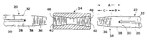
Referring initially to Figure 1 there is illustrated the components of
a taper thread deformed reinforcing bar splice in accordance with the
present invention. The splice includes bar 20, bar 22, and the joining
internally threaded sleeve 24. While the bars shown are of the same
size, they can vary in bar size by use of well known transition couplers
with different size threads in each end matching that of the bars. The
bar 22 and its threaded end will be described in detail.
Typically, the bar is deformed during the rolling process and is
provided with longitudinal diametrically opposite Iong ribs shown at 26
and 28 on opposite sides of the bar. Included are circumferential ribs 30
somewhat offset from circumferential ribs on the opposite side as shown
at 32.
It will be appreciated that commercially available reinforcing bar
may be provided with a wide variety of rib or deformation patterns.
Such patterns usually include the longitudinal diametrically opposite
ribs and circumferential ribs extending either normal to the axis of the
bar or at an angle. Some bars are provided with thread form
deformations. For more details of the various bar deformations
available, reference may be had to various publications of the Concrete
Reinforcing Steel Institute (CRSI) of Chicago, Illinois, U.S.A. It will also
be appreciated that deformed bars of the type illustrated come in various
sizes and bar size designations may vary from Number #3 ( 10 mm) to
Number # 18 (57mm), for' example, A Number #3 ( 10 mm) bar may, for
example, have a nominal diameter of .375" (9.53 mm) and weigh about
.376 pounds (0.171 kg) per foot (3.048 dm). On the other hand a
Number # 18 (57mm) bar may have a nominal diameter of 2.257"
(57.3 mm) and weigh 13.6 pounds (6.169 kg) peer foot (3.048 dm).
Needless to say that when bars are of the larger size and substantial
length, they become difficult to handle, clamp, and properly support.
-6-
CA 02469583 2004-06-02
The bar 22 has a cold formed insection 34 (A) which includes a
threaded tip section 36 (C) and an unthreaded cold formed swaged
cylindrical section 38 (B). The capital letters, as illustrated at the right
hand side of Figure 1 refer to the axial length of such sections. It is
preferable that the axial length of the swaged section (A) be subsfantially
longer than the length of the threads (C) so that the ends or mouth of
the coupler shown at 40 and 42 will be well within the swaged area (A).
When the coupler is assembled the mouth 42 will be substantially at the
inner end of the thread section (C) and at least the distance (B) extends
beyond the mouth of the coupler. The length of the extending swaged
section (B) is about one-half of (C) and preferably from about 1/3 to about
2/3 of (C), or more. Stated another way, the extending swaged section (B)
is about
~/3 to about 2/3 of (A). Preferably, the length of the threads (C) is from
about 2/3 to about 1/2 of (A).
The sleeve 24 may be formed from hex or round stock and has
internal threads at each end shown at 46 and 48, matching the tapered
threads at 36. The internal tapered threads in the sleeve 24 are slightly
longer than the external threads on the tapered bar end but the sleeve
may be assembled quickly to the bar ends with relatively few turns and
correct torque.
A similar splice or coupling is shown in Figure 2 but instead of
taper threads the bar ends and coupling sleeve are provided with
straight or parallel threads. As in the tapered thread couplers the bar
ends have a section or area which has been cold formed indicated by the
dimension (A) shown at 56 which includes the thread length (C) shown
at 58 and cylindrical swaged section (B) shown at 60. The sleeve 54 also
_7_
CA 02469583 2004-06-02
may be formed from hex or round stock and has a completely threaded
internal bore indicated at 62. The sleeve will be threaded on one bar end
and the other bar end into the sleeve until the bar ends abut at
substantially the midpoint of the sleeve. The sleeves and/or bars are
tightened to form the splice. The parallel thread connection shown in
Figure 2 requires much more turning and manipulation of the bars than
the taper thread connection seen in Figure 1. When the bars abut and
are tightened, each mouth of the sleeve shown at 64 and 66 will be
positioned approximately at the ends of the threads (Cj and well within
the swaged section (A). Locking rings 67 threaded on the bars may be
tightened against the sleeve ends to secure the coupling and reduce any
play or slip.
Referring now to Figures 3 through 6, there is illustrated the
process of cold forming the bar end to obtain the cold worked section (A)
prior to threading. The cold forming process is accomplished by radially
compressing the bar 22 between two dies shown at 68 and 70, which
includes cylindrical half round cavities shown at 72 and 74, respectively.
Each cavity includes a flared end such as seen at 76 and 78 to avoid
pressing a sharp corner into the bar. The radius of the cylindrical
portion of the cavity is approximately equivalent the nominal diameter of
the bar 22. The nominal diameter of the bar is the diameter of the core
of the bar not including the projecting deformations such as the ribs 26,
28, or 32. Also, as seen in Figure 3, when cut by shear equipment, the
bar end tends to be slightly bent as shown at 80 and any bent portion of
the bar between the dies will be straightened during the compression or
cold forming steps.
The die 70 may be fixed as indicated at 82, while the die 68 is
mounted in slides 84 and 86 and is moved between opened and closed
positions by relatively large piston-cylinder assembly 88 connected to
_g_
CA 02469583 2004-06-02
the die by rod 90. The bar is supported by several rests or a table
indicated at 92 in the proper position for die engagement when the dies
are closed. No complex or powerful clamps are required to keep the bar
from moving axially, although bar end gauges may be provided simply to
position fhe bar properly from one or the other ends. When the dies are
closed the section of the bar between the cylindrical portions of the die
cavities will be radially compressed and the force of the dies literally will
flatten any projections on the bar end section being compressed.
Preferably, the bar end section may be subject to two such compression
operations and between such first and second compression operations
the bar is rotated about its axis 90° as indicated by the arrow 94 in
Figure 5. After such axial rotation, if desired, the bar end section being
formed is subjected to a second compression stroke as indicated in
Figure 6. It may be appreciated that additional compression strokes
may be performed on the bar end section being cold formed, but it has
been found that one or two are sufficient substantially to flatten or
compress any of the projecting ribs or deformations on the bar end
section and further compression steps are of minimal cold working
value.
Referring now to Figure 7 and 8, it will be seen that the bar 22
cold worked by the dies 58 and 70 now has a section indicated at 96
which has been subjected to the die pressure by radial compression and
such radial compression has literally flattened any ribs or projections
into the core of the bar and has cold worked the bar end throughout the
section 96. If desired, the tip of the bar indicated at 98 extending
beyond the formed or compressed section 96 may be cut off leaving a bar
end such as seen in Figure 8 with the cold worked section 96 to receive
the threads of either Figure 1 or Figure 2. The bar tip 98 rnay be cut off
either prior to or during the threading operation. Tapered or parallel
_g_
CA 02469583 2004-06-02
threads may then be formed on the bar end either by cutting or rolling
producing a bar end such as seen in Figures 1 or 2. The length of the
threads from the tip 100 will not embrace the entire cold worked or
compressed section 96 but rather leave a rather substantial portion so
that the cold worked section of the bar end extends well beyond the
mouth of the coupler.
Figure 9 is a view like Figure 3 but the dies shown at 102 and 104
have a slightly different configuration. As seen in Figure 9 each half
round die section includes a flared entrance 106, a cylindrical section
108, a somewhat longer tapered section 110 and a flared entrance 112.
Subjecting the bar, if desired, to two radial compressions with the bar
being rotated 90° between such compressions produces a bar end
tapered formed configuration such as shown in Figure 10. The
cylindrical section 108 of the dies produces the cylindrical section 114
on the bar end while the tapered section 110 produces the tapered
section 116.
The bar end or tip may be cut off as indicated at 118 or 120
depending upon the length of the taper desired. If cut off at 120 this
leaves the somewhat shorter tapered cold formed section 122 seen in
Figure 11 which is adjacent to the cylindrical cold formed section 114.
The cold worked and tapered section 122 may now be provided with
tapered threads either cut or rolled. If cut, the process requires less
metal or material to be removed in the thread forming operation. It also
facilitates taper thread rolling. Again the cold 'worked, formed, or
radially compressed area of the bar end extends well beyond the tapered
section and thus will extend beyond the mouth of the coupler when the
splice is completed.
It can now be seen that there is provided a coupling or splice for
deformed concrete reinforcing bar which provides an enhanced tensile
-10-
CA 02469583 2004-06-02
capability at minimal cost. The bar end is cold formed or radially
compressed to improve its strength by cold working literally flattening or
compressing the projections in an area of the bar end prior to threading.
The length of the cold working of the bar by such radial compression
S forming is longer than the length of the threads on the bar end so that
the mouth of the coupler will be positioned well within the area of
forming or cold working.
With the present invention a splice or coupler of superior tensile
capabilities can be achieved with minimal field working and cost.
Although the invention has been shown and described with
respect to certain preferred embodiments, it is obvious that equivalent
alterations and modifications will occur to others skilled in the art upon
the reading and understanding of this specification. The present
invention includes all such equivalent alterations and modifications, and
is limited only by the scope of the claims.
-11-